Page 3417 of 4323
 Taillight does not go off when light control switch is in OFF posi-
tion.
1. TAILLIGHT Relay
2. Light Control Swit")
± BODY ELECTRICALTROUBLESHOOTING
BE±5
3409 Author�: Date�:
2005 SEQUOIA (RM1146U) Taillight does not go off when light control switch is in OFF posi-
tion.
1. TAILLIGHT Relay
2. Light Control Switch
3. Wire Harness
4. Body ECUBE±27
BE±27
±
±
Headlight does not come on when engine is running and light
control switch is in OFF position .
1. ECU±B Fuse
2. MAIN Fuse
3. HEAD Relay
4. DRL Fuse
5. DRL No. 4 Relay
6. DIMMER Relay
7. Parking Brake Switch
8. Wire Harness
9. Body ECUBE±14
BE±14
BE±27
BE±14
BE±27
BE±55
BE±55
±
±
FOG LIGHT SYSTEM
This system uses the multiplex communication system, so check diagnosis system of the multiplex commu-
nication system before you proceed with troubleshooting.
SymptomSuspect AreaSee page
Fog light does not come on with light control switch is in HEAD
position.
(Headlight is normal.)
1. FOG Fuse
2. FOG LIGHT Relay
3. Fog Light Switch
4. Wire Harness
5. Body ECUBE±14
BE±27
BE±34
±
±
Fog light does not come on with light control switch is in HEAD
position.
(Headlight does not light).1.*1 Other Parts
2. Wire Harness±
±
Only one light does not come on.1. Bulb
2. Wire Harness±
±
*1: Inspect Headlight System
TURN SIGNAL AND HAZARD WARNING SYSTEM
SymptomSuspect AreaSee page
ºHazardº and ºTurnº do not light up.
1. GAUGE Fuse
2. TURN±HAZ Fuse
3. Ignition Switch
4. Turn Signal Flasher Relay
5. Wire HarnessBE±14
BE±14
BE±24
BE±24
±
Hazard warning light does not light up.
(Turn is normal)1. Hazard Warning Switch
2. Wire Harness
3. Turn Signal Flasher RelayBE±36
±
BE±36
Turn signal does not light up.
(Hazard is normal)1. Turn Signal Switch
2. Wire Harness
3. Turn Signal Flasher RelayBE±36
±
BE±36
Turn signal does not light up in one direction.1. Bulb
2. Wire Harness±
±
Only one bulb does not light up.1. Bulb
2. Wire Harness±
±
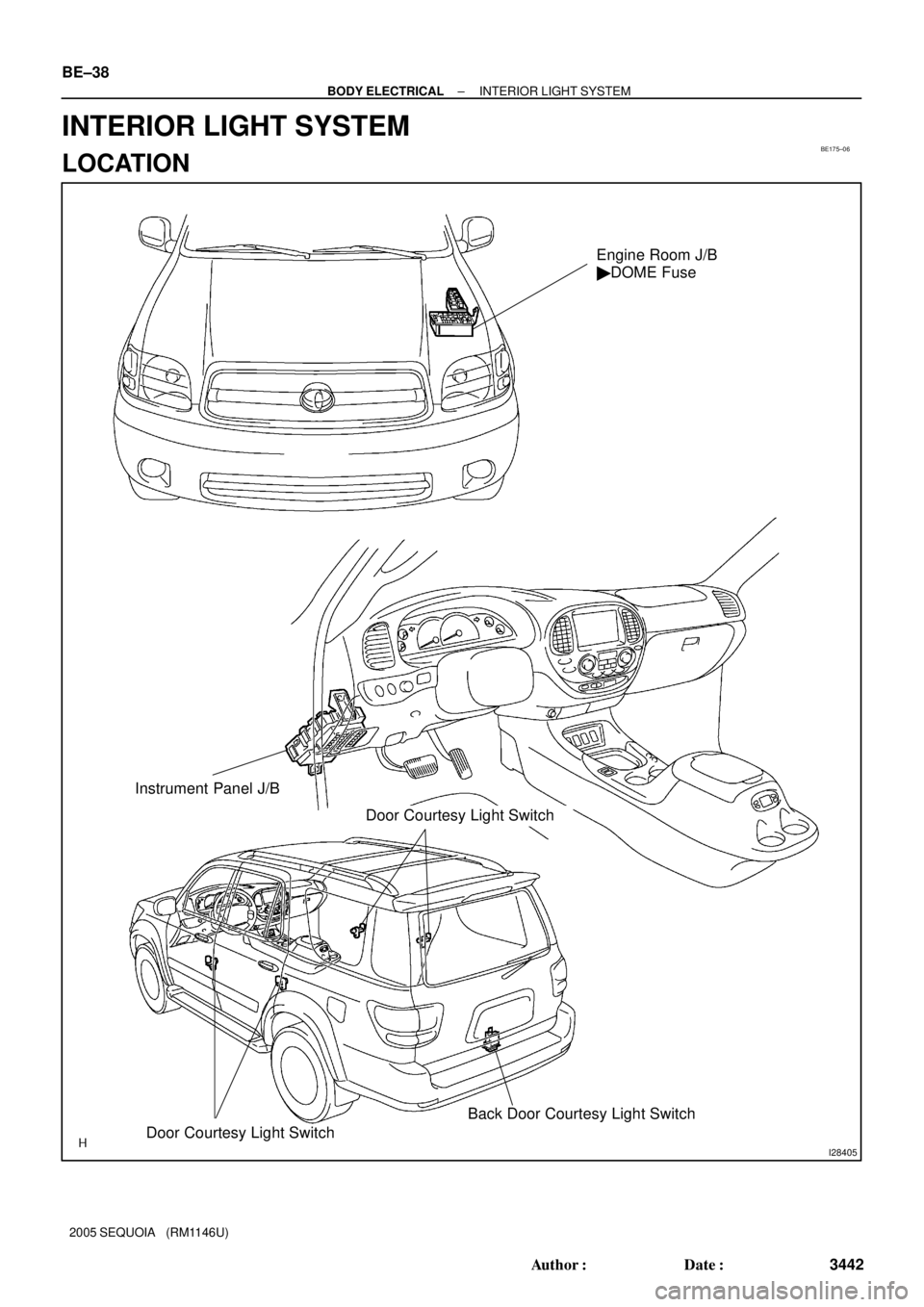
INTERIOR LIGHT SYSTEM
This system uses the multiplex communication system, so check diagnosis system of the multiplex commu-
nication system before you proceed with troubleshooting.
SymptomSuspect AreaSee page
All the interior lights do not come on.
1. DOME Fuse
2. Illumination Circuit
3. Body ECUBE±14
DI±1759
±
Page 3418 of 4323
 The interior light does not come on when the drivers door is
opened.
1. Drivers Door Courtesy Light Switch
2. Wi")
BE±6
± BODY ELECTRICALTROUBLESHOOTING
3410 Author�: Date�:
2005 SEQUOIA (RM1146U) The interior light does not come on when the driver's door is
opened.
1. Driver's Door Courtesy Light Switch
2. Wire Harness
3. Body ECUBE±40
±
±
The light does not come on when the passenger's door is opened.
1. Passenger's Door Courtesy Light Switch
2. Wire Harness
3. Body ECUBE±40
±
±
The light does not come on when the rear±right door is opened.
1. Rear±Right Door Courtesy Light Switch
2. Wire Harness
3. Body ECUBE±40
±
±
The light does not come on when the rear±left door is opened.
1. Rear±Left Door Courtesy Light Switch
2. Wire Harness
3. Body ECUBE±40
±
±
Only one of the bulbs comes on.Bulb±
The illumination does not fade out when all the doors are closed.1. Courtesy Light Switch
2. Body ECUBE±40
±
The illumination does not fade out immediately when all the doors
are locked within 15 seconds after they are closed.1. Door Unlock Detection Switch
2. Body ECUBE±79
±
Front personal light does not come on.
1. Bulb
2. Front Personal Light
3. Wire Harness±
BE±40
±
Room light does not come on.
1. Bulb
2. Room Light
3. Wire Harness±
BE±40
±
Vanity light does not come on.
1. Bulb
2. Vanity Light
3. Wire Harness±
BE±40
±
Luggage Room light does not come on.
1. Bulb
2. Back Door Courtesy Light Switch
3. Body ECU±
BE±40
±
Courtesy light does not come on.
1. Bulb
2. Door Courtesy Light Switch
3. Body ECU±
BE±40
±
Does not operate the illuminated entry1. Illumination Circuit
2. Body ECUDI±1759
±
All functions of the body control system do not operate.1. Power Source Circuit
2. Body ECUDI±1700
±
BACK±UP LIGHT SYSTEM
SymptomSuspect AreaSee page
Back±Up Light does not come on.
1. Bulb
2. GAUGE Fuse
3. BACK±UP LIGHT Relay
4. Instrument Panel J/B (IPO) Circuit
5. Ignition Switch
6. Wire Harness±
BE±14
BE±45
BE±20
BE±24
±
Back±Up Light always remains on.
1. Park/Neutral Position Switch
2. BACK±UP LIGHT Relay
3. Wire HarnessDI±576
BE±45
±
Only one light does not come on.1. Bulb
2. Wire Harness±
±
Page 3450 of 4323
BE175±06
I28405
Door Courtesy Light SwitchBack Door Courtesy Light Switch
Engine Room J/B
� DOME Fuse
Instrument Panel J/B
Door Courtesy Light Switch
BE±38
± BODY ELECTRICALINTERIOR LIGHT SYSTEM
3442 Author�: Date�:
2005 SEQUOIA (RM1146U)
INTERIOR LIGHT SYSTEM
LOCATION
Page 3451 of 4323
I18593
Front Personal Light
Rear Interior Light Vanity Light
Door Courtesy Light
Front Personal Light
Luggage Room Light
± BODY ELECTRICALINTERIOR LIGHT SYSTEM
BE±39
3443 Author�: Date�:
2005 SEQUOIA (RM1146U)
Page 3452 of 4323

BE2MS±01
I18639
39
13
Front Personal Light Switch
I18755
1 3
Front Personal
Light Switch
I18563
31
Rear Interior Light Switch
I18564
2
3
I28729
31
BE±40
± BODY ELECTRICALINTERIOR LIGHT SYSTEM
3444 Author�: Date�:
2005 SEQUOIA (RM1146U)
INSPECTION
1. w/o Sliding Roof:
INSPECT FRONT PERSONAL LIGHT SWITCH CONTI-
NUITY
(a) Disconnect the connector from the personal light.
(b) Push the personal light switch ON, check that continuity
exists between terminal 9 and terminal 13.
If continuity is not as specified, replace the light assembly or
bulb.
2. w/ Sliding Roof:
INSPECT FRONT PERSONAL LIGHT SWITCH CONTI-
NUITY
(a) Disconnect the connector from the personal light.
(b) Push the personal light switch ON, check that continuity
exists between terminal 1 and terminal 3.
If continuity is not as specified, replace the light assembly or
bulb.
3. w/o RSE or RSA:
INSPECT REAR INTERIOR LIGHT SWITCH CONTINU-
ITY
(a) Disconnect the connector from the doom light.
(b) Push the rear interior light switch ON, check that continu-
ity exists between terminal 1 and terminal 3.
If continuity is not as specified, replace the light assembly or
bulb.
(c) Turn the light switch to DOOR, check that continuity exists
between terminals 2 and 3.
If continuity is not as specified, replace the light assembly or
bulb.
4. w/ RSE or RSA:
INSPECT REAR INTERIOR LIGHT SWITCH CONTINU-
ITY
(a) Disconnect the connector from the rear interior light.
(b) Push the rear interior light switch ON, check that continu-
ity exists between terminal 1 and terminal 3.
If continuity is not as specified, replace the light assembly or
bulb.
Page 3453 of 4323

(c) Turn the light switch to DOOR, check that co")
I28730
32
N08313
2
N08314
1
2
N20159
ON
OFFOhmmeter
I04056
± BODY ELECTRICALINTERIOR LIGHT SYSTEM
BE±41
3445 Author�: Date�:
2005 SEQUOIA (RM1146U)
(c) Turn the light switch to DOOR, check that continuity exists
between terminals 2 and 3.
If continuity is not as specified, replace the light assembly or
bulb.
5. INSPECT LUGGAGE ROOM LIGHT SWITCH CONTI-
NUITY
(a) Disconnect the connector from the interior light assembly.
(b) Turn the interior light switch ON, check that continuity ex-
ists between terminal 2 and body ground.
If continuity is not as specified, replace the light assembly or
bulb.
(c) Turn the interior light switch to DOOR, check that continu-
ity exists between terminals 1 and 2.
If continuity is not as specified, replace the light assembly or
bulb.
6. INSPECT DOOR COURTESY LIGHT SWITCH CONTI-
NUITY
(a) Check that continuity exists between terminals and the
switch body with the switch ON (switch pin released:
opened door).
(b) Check that no continuity exists between terminals and the
switch body with the switch OFF (switch pin pushed in:
closed door).
If continuity is not as specified, replace the switch.
7. INSPECT DOOR COURTESY LIGHT CONTINUITY
Check that continuity exists between terminals.
If continuity is not as specified, replace the light assembly or
bulb.
Page 3454 of 4323
I18562
I18561
BE±42
± BODY ELECTRICALINTERIOR LIGHT SYSTEM
3446 Author�: Date�:
2005 SEQUOIA (RM1146U)
8. INSPECT VANITY LIGHT CONTINUITY
Switch positionTester connectionSpecified condition
OFF (Closed)1 ± 2No continuity
ON (Opened)1 ± 2Continuity
If continuity is not as specified, replace the bulb or vanity light.
9. INSPECT BACK DOOR COURTESY LIGHT SWITCH
CONTINUITY
Switch positionTester connectionSpecified condition
OFF (Closed)1 ± 2No continuity
ON (Opened)1 ± 2Continuity
If continuity is not as specified, replace the switch.
Page 3494 of 4323

THEFT DETERRENT SYSTEM
ON±VEHICLE INSPECTION
1. OUTLINE OF THEFT DETERRENT SYSTEM
When the thef")
BE2ML±01
BE±82
± BODY ELECTRICALTHEFT DETERRENT SYSTEM
3486 Author�: Date�:
2005 SEQUOIA (RM1146U)
THEFT DETERRENT SYSTEM
ON±VEHICLE INSPECTION
1. OUTLINE OF THEFT DETERRENT SYSTEM
When the theft deterrent system detects any theft, it informs
people around by flashing lights and sound.
All initial settings are performed in active mode. It can be
switched to passive mode by using the hand±held tester. (See
step 3. CHANGING METHOD OF PASSIVE MODE.)
HINT:
There are 4 conditions in this system: disarmed state, arming
preparation, armed state and alarm sounding.
(1) Disarmed state
�Alarm function does not operate.
�Theft deterrent function is not performed.
(2) Arming preparation
�Time until transferring to armed state.
�Theft deterrent function is not performed.
(3) Armed state
Theft deterrent function is ready.
(4) Alarm sounding:
When the system detects a theft, it informs people
around the vehicle using light and sound.
Refer to the table below for alarming method or
time.
Horn
Security horn
Alarm methodHeadlightAlarm method
Taillight
Interior light
Alarm time60 seconds
Alarm outputContinuous 0.4 secs. (ON)
0.4 secs. (OFF)
HINT:
Alarm output for the hazard is the same as the one for the haz-
ard on the vehicle.
If any of the doors is unlocked not by the key or wireless remote
control in the armed state, a force lock signal will be output.