Page 371 of 4323

Idling
Ignition Switch OFF
3 to 5 minutes
Time 2 minutes
(a), (b), (c)(e)
(d)
± DIAGNOSTICSENGINE
DI±177
371 Author�: Date�:
2")
B17397
Vehicle Speed
Between
38 mph and 75 mph
(60 km/h and 120 km/h)
Idling
Ignition Switch OFF
3 to 5 minutes
Time 2 minutes
(a), (b), (c)(e)
(d)
± DIAGNOSTICSENGINE
DI±177
371 Author�: Date�:
2005 SEQUOIA (RM1146U)
15 Perform confirmation driving pattern.
(a) Connect the hand±held tester to the DLC3.
(b) Turn the ignition switch to ON and turn the tester ON.
(c) Clear DTCs (see page DI±43).
(d) Switch the ECM from normal mode to check mode using the tester (see page DI±44).
(e) Start the engine and warm it up with all the accessories switched OFF.
(f) Drive the vehicle at between 38 mph and 75 mph (60 km/h and 120 km/h) and at an engine speed of
between 1,400 rpm and 3,200 rpm for 3 to 5 minutes.
HINT:
If the system is still malfunctioning, the MIL will be illuminated during step (e).
NOTICE:
If the conditions in this test are not strictly followed, no malfunction will be detected.
NEXT
16 Check whether DTC output recurs (DTC P0171, P0172, P0174 or P0175)
CHECK:
(a) On the hand±held tester, select the following menu items: DIAGNOSIS / ENHANCED OBD II / DTC
INFO / PENDING CODES.
(b) Read DTCs.
RESULT:
Display (DTC Output)Proceed To
P0171, P0172, P0174 or P0175A
No outputB
B Go to step 5.
A
Page 376 of 4323

INSPECTION PROCEDURE
HINT:
Read freeze frame data using the hand-held tester. Freeze frame data records")
B17411
E6E1
FPR
A21024
DI±182
± DIAGNOSTICSENGINE
376 Author�: Date�:
2005 SEQUOIA (RM1146U)
INSPECTION PROCEDURE
HINT:
Read freeze frame data using the hand-held tester. Freeze frame data records the engine conditions when
a malfunction is detected. When troubleshooting, freeze frame data can help determine if the vehicle was
running or stopped, if the engine was warmed up or not, if the air±fuel ratio was lean or rich, as well as other
data from the time when a malfunction occurred.
1 Check voltage between terminal FPR and E1 of ECM.
CHECK:
Measure the voltage between terminals of E6 and E6 ECM con-
nectors.
OK:
Tester ConnectionConditionSpecified Condition
FPR (E6±30) ± E1 (E6±1)STA signal ON9 to 14 V
FPR (E6±30) ± E1 (E6±1)STA signal OFF0 to 3 V
OK Replace ECM (See page SF±80).
NG
2 Check fuel pump relay.
PREPARATION:
Remove the fuel pump relay from the engine room R/B.
CHECK:
Inspect the fuel pump relay.
OK:
Terminal No.ConditionSpecified Condition
3 ± 4Apply B+ between
terminals 1 and 210 KW or higher
3 ± 4AlwaysBelow 1 W
3 ± 5Always10 KW or higher
3 ± 5Apply B+ between
terminals 1 and 2Below 1 W
NG Replace fuel pump relay.
OK
Page 377 of 4323
A21377
Engine Room J/B:
Fuel Pump
Relay
B17414
E6ECM Connector
FPR
± DIAGNOSTICSENGINE
DI±183
377 Author�: Date�:
2005 SEQUOIA (RM1146U)
3 Check for open and short in harness and connector between fuel pump relay
and ECM.
PREPARATION:
(a) Remove the fuel pump relay from the engine room J/B.
(b) Disconnect the E6 ECM connector.
CHECK:
Measure the resistance between wire harness side connectors.
OK:
Standard:
Tester ConnectionSpecified Condition
Engine Room J/B (Fuel pump relay ter-
minal 1) ± FPR (E6±30)Below 1 W
Engine Room J/B (Fuel pump relay ter-
minal 1) or FPR (E6±30) ±
Body ground
10 kW or higher
NG Repair or replace harness or connector.
OK
Replace ECM (See page SF±80).
Page 381 of 4323

TYPICAL ENABLING CONDITIONS
ItSpecificationItemMinimumMaximum
The monitor will run whenever these
DTCs are not presentSee page")
± DIAGNOSTICSENGINE
DI±187
381 Author�: Date�:
2005 SEQUOIA (RM1146U)
TYPICAL ENABLING CONDITIONS
ItSpecificationItemMinimumMaximum
The monitor will run whenever these
DTCs are not presentSee page DI±18
Battery voltage8 V±
Throttle position learningCompleted
VVT systemNormal operate by scan±tool
Engine RPM400 to 5,700rpm
All of the following conditions are met:Condition 1 and 2
1. Engine coolant temperature±10�C (14�F)±
2. Either of the following conditions is met:Condition (a) or (b)
(a) Engine coolant temperature at engine
start±7�C (19�F)±
(b) Engine coolant temperature20�C (68�F)±
Fuel±cutOFF
Emission±related±misfire:
First 1,000 revolutions after engine start,
or check modeCrankshaft 1,000 revolutions
Except aboveCrankshaft 1,000 revolutions x 4
Catalyst±damage±misfire (MIL blinks):
All of the following conditions 1, 2 and 3
are metCrankshaft 200 revolutions
1. Driving cycle1st
2. Check modeOFF
3. Engine RPM±2,800 rpm
Except aboveCrankshaft 200 revolutions x 3
TYPICAL MALFUNCTION THRESHOLDS
Detection CriteriaThreshold
Emission±related±misfire:
Misfire rate:1.2 % or more
Catalyst±damage±misfire (MIL blinks):
Number of misfire per 200 revolutions93 or more
(varies with intake air amount and RPM)
Multiple cylinders misfireDetected
MONITOR RESULT
Refer to page DI±26 for detailed information.
The test value and test limit information are described as shown in the following table. Check the monitor
result and test values after performing the monitor drive pattern (refer to ºConfirmation Monitorº).
�MID (Monitor Identification Data) is assigned to each emissions±related component.
�TID (Test Identification Data) is assigned to each test value.
�Scaling is used to calculate the test value indicated on generic OBD ll scan tools.
Page 384 of 4323

A15466A19380
Battery I18
Ignition SW
1
#80 #60 #40#20
#70#50ECM
#30 #10
6
2
I10 Injector No.2
I12 Injector No.4
I13 Injector No.5
I14 Injector No.6
I15 Injector No.7
I16 Injector No.8
7
1
2
12
1
2 1
2
1
2
2
2
2 3 2
5
7 4
I9 Injector No.1
1C
2D1
B
F10
Fusible Link BlockIGN2
Engine Room J/B
54
B2C1 1C
1J 1D 2
3
W±R6
AM2Instrument Panel J/B
W±R3
B±R
1
1
1
I11 Injector No.3
IG413
E8 E6
E6
E8 E6 E6
E6 E6
R±W B±R
B±R
B±R
B±R
B±R
B±R
B±RY R±B
L±R W
L G R
B±R B±R B±R
5
IG2
AM2
B±R
B±R
B±R
B±R
B±R
DI±190
± DIAGNOSTICSENGINE
384 Author�: Date�:
2005 SEQUOIA (RM1146U)
WIRING DIAGRAM
Refer to DTC P0351 on page DI±221 for the wiring diagram of the ignition system.
CONFIRMATION DRIVING PATTERN
(a) Connect the hand±held tester to the DLC3.
(b) Record DTC and the freeze frame data.
(c) Use the hand±held tester to set the check mode (See page DI±44).
(d) Read the value on the misfire counter for each cylinder when idling. If the value is displayed on the
misfire counter, skip the following procedure of confirmation driving.
(e) Drive the vehicle several times with the engine speed, load and surrounding range shown as ENGINE
SPD, CALC LOAD in the freeze frame data or MISFIRE RPM, MISFIRE LOAD in the DATA LIST.
If you have no hand±held tester, turn the ignition switch OFF after the symptom is simulated once. Then re-
peat the simulation process again.
Page 386 of 4323

1 Are there any other codes (besides DTC P0300, P0301, P0302, P0303, P0304
P0305, P0306, P0307 or P0308) being output?
PREPARA")
DI±192
± DIAGNOSTICSENGINE
386 Author�: Date�:
2005 SEQUOIA (RM1146U)
1 Are there any other codes (besides DTC P0300, P0301, P0302, P0303, P0304
P0305, P0306, P0307 or P0308) being output?
PREPARATION:
(a) Connect the hand±held tester to the DLC3.
(b) Turn the ignition switch ON and push the hand±held tester main switch ON.
(c) When using hand±held tester, enter the following menu: DIAGNOSIS / ENHANCED OBD II / DTC
INFO / CURRENT CODES.
CHECK:
Read the DTCs using hand±held tester.
RESULT:
Display (DTC Output)Proceed to
ºP0300, P0301, P0302, P0303, P0304, P0305, P0306, P0307 and/or
P0308ºA
ºP0300, P0301, P0302, P0303, P0304, P0305, P0306, P0307 or
P0308º and other DTCsB
HINT:
If any other codes besides ºP0300, P0301, P0302, P0303, P0304, P0305, P0306, P0307 or P0308º are
output, perform the troubleshooting for those DTCs.
B Go to relevant DTC chart (See page DI±58).
A
2 Check wire harness, connector and vacuum hose in engine room.
CHECK:
(a) Check the connection conditions of the wire harness and connector.
(b) Check for the disconnection, piping and brake of the vacuum hose.
NG Repair or replace, then confirm that there is no
misfire (See confirmation driving pattern).
OK
Page 388 of 4323
A19885
0.8 mm
(0.031 in.)
DI±194
± DIAGNOSTICSENGINE
388 Author�: Date�:
2005 SEQUOIA (RM1146U)
5 Check spark plug and spark of misfiring cylinder.
PREPARATION:
(a) Remove the ignition coil assembly.
(b) Remove the spark plug.
CHECK:
(a) Check the electrode for carbon deposits.
(b) Check the spark plug type (See page IG±1).
(c) Check electrode gap.
OK:
No large carbon deposit present.
Not wet with gasoline or oil.
Electrode gap: 0.8 mm (0.031 in.)
NOTICE:
If adjusting the gap of a new spark plug, bend only ºthe
base / groundº electrode. Do not touch the tip. Never at-
tempt to adjust the gap of a used plug.
PREPARATION:
(a) Install the spark plug to the ignition coil assembly.
(b) Disconnect the injector connector.
(c) Ground spark plug.
CHECK:
Check if spark occurs while engine is being cracked.
CAUTION:
Always disconnect each injector connector.
NOTICE:
Do not crank the engine for more than 2 seconds.
OK:
Spark occurs across electrode gap.
OK Go to step 8.
NG
Page 392 of 4323
B17411
#80
#70
#60
#50 #30
#20
#10
(+) (+)
(+)
(+)
(+) (+)(+)
#40(+)
E01 (±)
E8E6
DI±198
± DIAGNOSTICSENGINE
392 Author�: Date�:
2005 SEQUOIA (RM1146U)
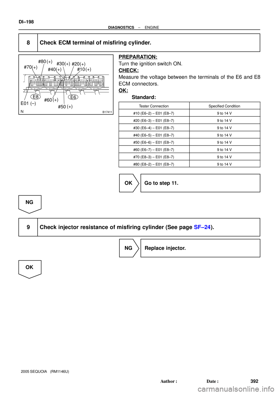
8 Check ECM terminal of misfiring cylinder.
PREPARATION:
Turn the ignition switch ON.
CHECK:
Measure the voltage between the terminals of the E6 and E8
ECM connectors.
OK:
Standard:
Tester ConnectionSpecified Condition
#10 (E6±2) ± E01 (E8±7)9 to 14 V
#20 (E6±3) ± E01 (E8±7)9 to 14 V
#30 (E6±4) ± E01 (E8±7)9 to 14 V
#40 (E6±5) ± E01 (E8±7)9 to 14 V
#50 (E6±6) ± E01 (E8±7)9 to 14 V
#60 (E6±7) ± E01 (E8±7)9 to 14 V
#70 (E8±3) ± E01 (E8±7)9 to 14 V
#80 (E8±2) ± E01 (E8±7)9 to 14 V
OK Go to step 11.
NG
9 Check injector resistance of misfiring cylinder (See page SF±24).
NG Replace injector.
OK