Page 1483 of 1943

7. INSTALL CRANKSHAFT PULLEY
(a) Clean the crankshaft pulle")
A11262
SST
SST
B00301
Seal
Packing
A11222
1
23
4
5
6
7
8
9
10
11
B11761
A13928
EM±24
± ENGINE MECHANICALTIMING CHAIN
2001 PRIUS (RM778U)
7. INSTALL CRANKSHAFT PULLEY
(a) Clean the crankshaft pulley inside.
(b) Install the pin to the crankshaft.
(c) Align the hole in the crank pulley with the pin position and
install the crank pulley.
(d) Using SST, install the pulley bolt.
SST 09213±70010, 09330±00021
Torque: 128 N´m (1,300 kgf´cm, 94 ft´lbf)
8. INSTALL CYLINDER HEAD COVER
(a) Remove any old packing (FIPG) material.
(b) Apply seal packing to 2 locations as shown in the illustra-
tion.
Seal packing:
Part No. 08826 ± 00080 or equivalent
(c) Install the gasket to the cylinder head cover.
HINT:
Part must be assembled within 3 minutes of application.
Otherwise the material must be remove and reapplied.
(d) Install the cylinder head cover and cable bracket with the
7 bolts, 2 seal washers and 2 nuts.
Uniformly tighten the bolts and nuts, in the several
passes, in the sequence shown.
Torque: 10 N´m (100 kgf´cm, 7 ft´lbf)
(e) Connect the 2 PCV hoses to the cylinder head cover.
9. CONNECT ENGINE WIRE TO CYLINDER HEAD COV-
ER
10. INSTALL IGNITION COILS (See page IG±7)
11. REMOVE RH ENGINE MOUNTING INSULATOR
Install the RH engine mounting insulator with the 5 bolts and 2
nuts.
12. INSTALL VSV TO RH ENGINE MOUNTING INSULA-
TOR
13. INSTALL DRIVE BELT
14. INSTALL ENGINE COOLANT RESERVOIR TANK
15. INSTALL AIR INLET
Page 1484 of 1943
A13934
A13907
± ENGINE MECHANICALTIMING CHAIN
EM±25
2001 PRIUS (RM778U)
16. CONNECT CONNECTORS
(a) Connect the Camshaft timing oil control valve connector.
(b) Connect the water temperature sensor connector.
(c) Connect the camshaft position sensor connector.
(d) Connect the 2 VSV connectors.
(e) Connect the 4 injector connectors.
(f) Connect the 4 ignition connectors.
17. INSTALL AIR CLEANER ASSEMBLY
(a) Install the air cleaner assembly with the 2 bolts.
(b) Tighten the 2 hose clamps.
(c) Connect the EVAP hose to the air cleaner case.
(d) Connect the MAF meter connector.
18. INSTALL BRAKE RESERVOIR TANK
19. INSTALL OUTER FR COWL TOP PANEL ASSEMBLY
(See page BO±35)
20. FILL WITH ENGINE COOLANT
21. INSTALL ENGINE UNDER COVERS
22. CONNECT BATTERY NEGATIVE (±) TERMINAL AND
HV BATTERY SERVICE PLUG (See page HV±1)
23. ROAD TEST VEHICLE
Check for abnormal noises, shock slippage, correst shift points
and smooth operation.
24. RECHECK ENGINE COOLANT AND HV TRANSAXLE
COOLANT
Page 1485 of 1943
EM1IW±02
A13929
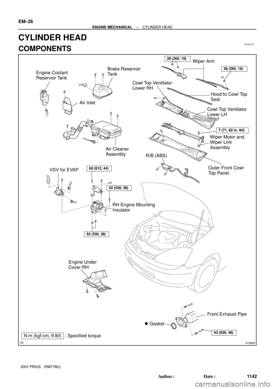
N´m (kgf´cm, ft´lbf)� Gasket
: Specified torque VSV for EVAPR/B (ABS) Air Cleaner
Assembly
RH Engine Mounting
Insulator Engine Coolant
Reservoir Tank
Engine Under
Cover RHOuter Front Cowl
Top Panel Air Inlet
60 (612, 44)
52 (530, 38)
52 (530, 38)
26 (265, 19)Brake Reservoir
Tank
Wiper Motor and
Wiper Link
Assembly
Cowl Top Ventilator
Lower LH
Cowl Top Ventilator
Lower RH
Wiper Arm
7 (71, 62 in. lbf)
26 (265, 19)
Hood to Cowl Top
Seal
62 (630, 46)
Front Exhaust Pipe
EM±26
± ENGINE MECHANICALCYLINDER HEAD
1142 Author�: Date�:
2001 PRIUS (RM778U)
CYLINDER HEAD
COMPONENTS
Page 1488 of 1943

REMOVAL
1. DISCONNECT BATTERY NEGATIVE (± )TERMINAL
AND HV BATTERY SERVICE PLUG
(See page HV±1)
2. REMOV")
EM1IX±02
A13907
B11761
A13934
± ENGINE MECHANICALCYLINDER HEAD
EM±29
2001 PRIUS (RM778U)
REMOVAL
1. DISCONNECT BATTERY NEGATIVE (± )TERMINAL
AND HV BATTERY SERVICE PLUG
(See page HV±1)
2. REMOVE OUTER FRONT COWL TOP PANEL AS-
SEMBLY (See page BO±32)
3. DRAIN HV TRANSAXLE COOLANT
(See page HT±6)
4. DRAIN ENGINE COOLANT
5. REMOVE CONVERTER AND INVERTER ASSEMBLY
(See page HV±18)
6. REMOVE AIR CLEANER ASSEMBLY
(a) Disconnect the MAF meter connector.
(b) Disconnect the EVAP hose from the air cleaner case.
(c) Loosen the 2 hose clamps.
(d) Remove the 3 bolts and air cleaner assembly.
7. REMOVE IGNITION COILS (See page IG±6)
8. REMOVE SPARK PLUGS (See page IG±1)
9. REMOVE PCV HOSES
10. REMOVE THROTTLE BODY (See page SF±28)
11. DISCONNECT ENGINE WIRE FROM CYLINDER HEAD
(a) Disconnect the ECT sensor connector.
(b) Disconnect the camshaft position sensor connector.
(c) Disconnect the oil control valve connector.
(d) Disconnect the 4 injector connectors.
(e) Remove the 3 bolts and disconnect the engine wire pro-
tector from the cylinder head cover.
Page 1506 of 1943

16. INSTALL INTAKE MANIFOLD
Install a new gasket, the intake manifold and 2 brackets with the
2 bolts and 2 nuts. Un")
A13935
A13934
A13907
EM±48
± ENGINE MECHANICALCYLINDER HEAD
2001 PRIUS (RM778U)
16. INSTALL INTAKE MANIFOLD
Install a new gasket, the intake manifold and 2 brackets with the
2 bolts and 2 nuts. Uniformly tighten the bolts and nuts in sever-
al passes.
Torque: 20 N´m (204 kgf´cm, 15 ft´lbf)
17. CONNECT ENGINE WIRE TO CYLINDER HEAD
(a) Install the engine wire protector to the cylinder head cover
with the 2 bolts.
(b) Connect the water ECT sensor connector.
(c) Connect the camshaft position sensor connector.
(d) Connect the oil control valve connector.
(e) Connect the 4 injector connectors.
18. INSTALL THROTTLE BODY
(See page SF±31)
19. INSTALL PCV HOSES
20. INSTALL SPARK PLUGS
(See page IG±1)
21. INSTALL IGNITION COILS (See page IG±7)
22. INSTALL AIR CLEANER ASSEMBLY
(a) Install the air cleaner assembly with the 2 bolts.
(b) Tighten the 2 hose clamps.
(c) Connect the EVAP hose to the air cleaner case.
(d) Connect the MAF meter connector.
23. INSTALL CONVERTER AND INVERTER ASSEMBLY
(See page HV±18)
24. INSTALL OUTER FR COWL TOP PANEL ASSEMBLY
(See page BO±32)
25. FILL WITH ENGINE COOLANT
26. FILL WITH HV COOLANT
27. INSTALL ENGINE UNDER COVERS
28. CONNECT BATTERY NEGATIVE (±) TERMINAL AND
HV BATTERY SERVICE PLUG (See page HV±1)
Page 1507 of 1943
± ENGINE MECHANICALCYLINDER HEAD
EM±49
2001 PRIUS (RM778U)
29. ROAD TEST VEHICLE
Check for abnormal noises, shock slippage, correct shift points
and smooth operation.
30. RECHECK ENGINE COOLANT AND HV COOLANT
Page 1508 of 1943
EM1IZ±02
A13904
Front BumperR/B (ABS)
Air Cleaner
Assembly Engine Coolant
Reservoir Tank
Engine Under
CoverOuter Front Cowl
Top Panel Air Inlet
Brake Reservoir
Tank
Wiper Motor and
Wiper Link
Assembly
Cowl Top Ventilator
Lower LH
Cowl Top Ventilator
Lower RH
Wiper Arm
Hood to Cowl Top
Seal
N´m (kgf´cm, ft´lbf) : Specified torque
26 (265, 19)
7 (71, 62 in. lbf)
26 (265, 19)
11.5 (117, 8)
Head Light RH
EM±50
± ENGINE MECHANICALENGINE UNIT
1166 Author�: Date�:
2001 PRIUS (RM778U)
ENGINE UNIT
COMPONENTS
Page 1511 of 1943

REMOVAL
1. DISCONNECT BATTERY NEGATIVE (±) TERMINAL
AND HV BATTERY SERVICE PLUG
(See page HV±1)
2. REMOVE OUTER F")
EM1J0±02
A13907
A13943
± ENGINE MECHANICALENGINE UNIT
EM±53
2001 PRIUS (RM778U)
REMOVAL
1. DISCONNECT BATTERY NEGATIVE (±) TERMINAL
AND HV BATTERY SERVICE PLUG
(See page HV±1)
2. REMOVE OUTER FRONT COWL TOP PANEL AS-
SEMBLY (See page BO±32)
3. DRAIN HV COOLANT (See page HT±8)
4. DRAIN ENGINE COOLANT
5. REMOVE CONVERTER AND INVERTER ASSEMBLY
(See page HV±18)
6. REMOVE HEATER UNIT WATER PUMP
(See page AC±55)
7. REMOVE AIR CLEANER ASSEMBLY
(a) Disconnect the MAF meter connector.
(b) Disconnect the EVAP hose from the air cleaner case.
(c) Loosen the 2 hose clamps.
(d) Remove the 2 bolts and air cleaner assembly.
8. DISCONNECT CONNECTORS, CLAMPS AND HOSES
(a) Disconnect the engine wire clamps.
(b) Disconnect the heated oxygen sensor connector.
(c) Disconnect the 2 power steering connectors.
(d) Disconnect the VSV connector for purge line.
(e) Disconnect the VSV hose for purge line.
(f) Disconnect the ground strap from RH fender apron.
(g) Disconnect the ground strap from LH fender apron.
9. REMOVE AIR INLET
10. REMOVE ENGINE COOLANT RESERVOIR TANK
11. DISCONNECT 2 RADIATOR HOSES FROM RADIATOR
12. DISCONNECT HEATER HOSE FROM CYLINDER
BLOCK

16. CONNECT CONNECTORS
(a) Connect the Camshaft timing oil control valve connector.
(b) Connect the water temperature sens")

29. ROAD TEST VEHICLE
Check for abnormal noises, shock slippage, correct shift points
and smooth operation.
30. RECHECK ENGINE COOLANT AN")

Air Cleaner
Assembly Engine Coolant
Reservoir Tank
Engine Under
CoverOuter Front Cowl
Top Panel Air Inlet
Brake Reservoir
Tank
Wiper Motor and
Wiper Link")