Page 1575 of 1943
B11773
Radiator Cap Tester
± COOLINGRADIATOR AND CONDENSER MODULE
CO±15
2001 PRIUS (RM778U)
3. INSPECT COOLING SYSTEM FOR LEAKS
(a) Fill the radiator with coolant and attach a radiator cap tes-
ter.
(b) Warm up the engine.
(c) Pump it to 118 kPa (1.2 kgf´cm
2, 17.1 psi), and check that
the pressure drops.
If the pressure drops, check the hoses, radiator or water pump
for leaks. If no external leaks are found, check the heater core,
cylinder block and head.
4. REINSTALL RADIATOR CAP
Page 1576 of 1943

REMOVAL
1. DISCHARGE REFRIGERANT FROM REFRIGERATION
SYSTEM
HINT:
At the time of installation, please refer")
CO145±01
I17955
I17954
± COOLINGRADIATOR AND CONDENSER MODULE
CO±17
2001 PRIUS (RM778U)
REMOVAL
1. DISCHARGE REFRIGERANT FROM REFRIGERATION
SYSTEM
HINT:
At the time of installation, please refer to the following item.
Evacuate air from refrigeration system.
Charge system with refrigerant and inspect for leakage of refrig-
erant.
Specified amount: 500 ± 50 g (17.64 ± 1.76 oz.)
2. DRAIN ENGINE COOLANT FROM RADIATOR
HINT:
It is not necessary to drain out all the coolant.
3. REMOVE ELECTRIC COOLING FAN ASSEMBLY
(See Page CO±22)
4. REMOVE FRONT BUMPER (See Page BO±4)
5. REMOVE RADIATOR RESERVOIR HOSE
6. DISCONNECT DISCHARGE AND LIQUID TUBE
(a) Remove the 2 bolts and disconnect discharge and liquid
tube.
Torque: 5.4 N´m (55 kgf´cm, 48 in.´lbf)
NOTICE:
Cap open the fittings immediately to keep moisture or dirt
out of the system.
HINT:
At the time of installation, please refer to the following item.
Lubricate 2 new O±rings with compressor oil and install them
to the tubes.
(b) Remove the bolt.
(c) Disconnect the liquid tube and remove the bracket.
7. REMOVE RADIATOR UPPER SUPPORT
Remove the 2 bolts and 2 radiator upper supports.
Page 1578 of 1943

REMOVAL
1. DISCHARGE REFRIGERANT FROM REFRIGERATION
SYSTEM
HINT:
At the time of installation, please refer to the fo")
CO149±01
I17963
I17964
CO±22
± COOLINGELECTRIC COOLING FAN
2001 PRIUS (RM778U)
REMOVAL
1. DISCHARGE REFRIGERANT FROM REFRIGERATION
SYSTEM
HINT:
At the time of installation, please refer to the following item.
Evacuate air from refrigeration system.
Charge system with refrigerant and inspect for leakage of refrig-
erant.
Specified amount: 500 ± 50 g (17.64 ± 1.76 oz.)
2. DRAIN ENGINE COOLANT FROM RADIATOR
HINT:
It is not necessary to drain out all coolant.
3. REMOVE BRACKETS
(a) Remove the water hose from fan shroud.
(b) Remove the 5 bolts and 2 brackets.
4. REMOVE SUCTION AND DISCHARGE HOSES
(a) Remove the 2 bolts and disconnect the both hoses.
Torque: 10 N´m (100 kgf´cm, 7 ft´lbf)
HINT:
At the time of installation, please refer to the following item.
Lubricate 2 new O±rings with compressor oil and install them
to the tubes.
(b) Loosen the 2 nuts and remove the both hoses.
Torque:
Suction hose 32 N´m (330 kgf´cm, 24 ft´lbf)
Discharge hose 22 N´m (225 kgf´cm, 16 ft´lbf)
HINT:
At the time of installation, please refer to the following item.
Lubricate 2 new O±rings with compressor oil and install them
to the tubes.
Page 1584 of 1943
LU02M±08
A13942
Wiper Arm
VSV for EVAPAir Cleaner
Assembly
RH Engine Mounting
Insulator
Engine Under
Cover RH
N´m (kgf´cm, ft´lbf) : Specified torqueOuter Front Cowl
Top Panel
26 (265, 19)
52 (530, 38)
60 (612, 44)
52 (530, 38)
Air Inlet
Engine Coolant
Reservoir TankBrake reservoir
Tank
Wiper Motor and
Wiper Link
AssemblyHeat to Cowl Top
Seal
Cowl Top Ventilator
Lower LH Cowl Top Ventilator
Lower LH
R/B (ABS)
26 (265, 19)
7 (71, 62 in. lbf)
LU±4
± LUBRICATIONOIL PUMP
1310 Author�: Date�:
2001 PRIUS (RM778U)
OIL PUMP
COMPONENTS
Page 1605 of 1943

REMOVAL
1. REMOVE SERVICE PLUG (See page HV±1)
2. DRAIN HV COOLANT (See page HT±")
HV00A±01
B11977
B11979
B11980
HV±18
± HYBRID VEHICLE CONTROLCONVERTER AND INVERTER ASSEMBLY
2001 PRIUS (RM778U)
REMOVAL
1. REMOVE SERVICE PLUG (See page HV±1)
2. DRAIN HV COOLANT (See page HT±6)
3. REMOVE COWL TOP PANEL (See page BO±31)
4. VERIFY 0 V
NOTICE:
�Before starting step (a), 5 minutes or more should be
passed after removing the service plug.
�Be careful to prevent foreign matter from entering the
inside of connector cover.
(a) Disconnect the connector of the battery power cable and
insulate it with packaging tape.
(b) Using a torx socket wrench (T30), remove the 4 screws
and inverter terminal cover.
(c) Using a torx socket wrench (T40), remove the 2 screws,
circuit breaker sensor and connector cover.
HINT:
Slide the connector cover to disconnect the circuit breaker sen-
sor connector.
(d) Using a voltmeter, measure the voltage between termi-
nals of 3 phases (U±V, V±W, U±W) and each terminal and
body ground to verify them to be approx. 0 V.
5. REMOVE CONVERTER & INVERTER ASSEMBLY
(a) Remove the 6 bolts and 3 power cables for MG2.
NOTICE:
Be careful to prevent foreign matter from entering the in-
side of connector cover.
(b) Remove the 3 bolts and power cable for MG1.
NOTICE:
�Remove the power cable for MG1 together with con-
verter & inverter assembly.
�Be careful to prevent foreign matter from entering the
inside of connector cover.
(c) Remove the bolt and ground cable.
Page 1607 of 1943

INSTALLATION
1. INSTALL CONVERTER & INVERTER ASSEMBLY
(a)")
HV00D±01
B11978
B11980
B12004
B11979
A
A
AB
B
B
B12005
HV±22
± HYBRID VEHICLE CONTROLCONVERTER AND INVERTER ASSEMBLY
2001 PRIUS (RM778U)
INSTALLATION
1. INSTALL CONVERTER & INVERTER ASSEMBLY
(a) Install the converter & inverter assembly with the 4 bolts.
Torque: 21 N´m (214 kgf´cm, 15 ft´lbf)
(b) Connect the 3 water hoses to the converter & inverter as-
sembly.
(c) Connect the 4 connectors.
(d) Connect the 2 power cable connectors.
(e) Install the ground cable to the radiator upper support.
Torque: 8.0 N´m (82 kgf´cm, 71 in.´lbf)
(f) Install the power cable for MG1 with the 3 bolts.
Torque: 7.0 N´m (71 kgf´cm, 62 in.´lbf)
NOTICE:
Be careful to prevent foreign matter from entering the in-
side of connector cover.
(g) Install the connector cover and circuit breaker sensor with
the2 screws.
Torque: 20 N´m (204 kgf´cm, 15 ft´lbf)
(h) Connect the connector for circuit breaker sensor.
(i) Install the 3 power cables for MG2 with the 6 bolts.
Torque:
Bolt A: 19.5 N´m (199 kgf´cm, 14 ft´lbf)
Bolt B: 8.0 N´m (82 kgf´cm, 71 in.´lbf)
NOTICE:
Be careful to prevent foreign matter from entering the in-
side of connector cover.
(j) Install the gasket and inverter terminal cover with the 4
screws.
Torque: 8.0 N´m (82 kgf´cm, 71 in.´lbf)
2. INSTALL COWL TOP PANEL (See page BO±31)
3. INSTALL SERVICE PLUG (See page HV±1)
4. FILL WITH HV COOLANT (See page HT±6)
Page 1611 of 1943

HYBRID TRANSAXLE")
D09920Drain Plug
D09925
Oil Level
0 ± 5 mm
HT005±01
D09921Drain Plug
D09778
Shop Rag
D09899
HT±6
± HYBRID TRANSAXLEHYBRID TRANSAXLE UNIT
1379 Author�: Date�:
2001 PRIUS (RM778U)
HYBRID TRANSAXLE UNIT
ON±VEHICLE REPAIR
1. REPLACE TRANSAXLE OIL
Fluid type: ATF Type T±IV
Capacity: 4.6 liters (4.9 US qts, 4.0 Imp. qts)
Torque: 49 N´m (498 kgf´cm, 36 ft´lbf)
2. REPLACE COOLANT
(a) Remove the reservoir tank cap of the inverter.
(b) Remove the drain plug and drain the coolant.
(c) Install the drain plug with a new gasket.
(d) Loosen the 2 bleeder plugs and connect the hoses.
HINT:
To prevent coolant from splashing, place a shop rag on the
overflow pipe as shown in the illustration.
(e) Supply coolant from the reservoir tank.
(f) Supply coolant until coolant level in the hose connected
to the bleeder plugs reaches the same level with FULL of
the reservoir tank as shown in the illustration.
(g) Tighten the 2 bleeder plugs.
(h) Turn the ignition switch ON and active the water pump.
(i) Leave it as it is for approx. 20 seconds.
(j) Turn the ignition switch OFF.
(k) Loosen the 2 bleeder plugs to bleed air.
(l) Close the 2 bleeder plugs again.
Page 1612 of 1943
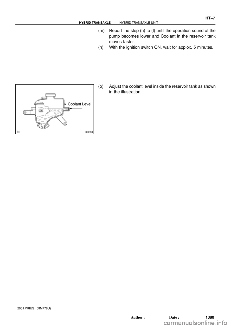
D09898
Coolant Level
± HYBRID TRANSAXLEHYBRID TRANSAXLE UNIT
HT±7
1380 Author�: Date�:
2001 PRIUS (RM778U)
(m) Report the step (h) to (l) until the operation sound of the
pump becomes lower and Coolant in the reservoir tank
moves faster.
(n) With the ignition switch ON, wait for applox. 5 minutes.
(o) Adjust the coolant level inside the reservoir tank as shown
in the illustration.

3. INSPECT COOLING SYSTEM FOR LEAKS
(a) Fill the radiator with coolant and attach a radiator cap tes-
te")
 : Specified torqueOuter Front Cowl
Top Panel
26 (265, 19)
52 (")