Page 121 of 1943
2001 PRIUS (EWD414U)
C8 CIGARETTE LIGHTER
2±GROUND : Approx. 12 volts with the ignition SW at ACC or ON position
1±GROUND : Always continuity
: PARTS LOCATION
CodeSee PageCodeSee PageCodeSee Page
C836J1137J2437
������ ���: JUNCTION BLOCK AND WIRE HARNESS CONNECTOR
CodeSee PageJunction Block and Wire Harness (Connector Location)
2D30Instrument Panel Wire and Instrument Panel J/B (Cowl Side Panel LH)
2K31Cowl Wire and Instrument Panel J/B (Cowl Side Panel LH)
: GROUND POINTS
CodeSee PageGround Points Location
ID42Cowl Side Panel LH
SERVICE HINTS
Page 130 of 1943
2001 PRIUS (EWD414U)
SHIFT LOCK
15A
STOP
2K 95A
ECU±IG
2I 2 10A
ACC FROM POWER SOURCE SYSTEM (
SEE PAGE 50)
2D 2
2 1
A E
B D
ID2 1
3 4
E E
B D
A E A AAAB A
2D 8
2K 8
ID AB B
D DID1 5 A C
B CA D
A D
4 JUNCTION
CONNECTOR J26
JUNCTION
CONNE CTOR J21 STOP
LIGHT
SW S 3
KEY INTERLOCK
SOLENOID
[UNLOCK
WARNING SW] U 1
JUNCTION
CONNECTOR J21
JUNCTION
CONNECTOR J11613
5
R±B G±W G± W G±W
GR±R
B±Y B±YGR±R GR±R
B±Y B±Y L W± B
W±B W±BW±B W±B W±B
SHIFT LOCK ECU S 2 STP ACC IG
W± BKLS+ E JUNCTION
CONNECTORB J14 , J15AJUNCTION
CONNECTORB J27 , J28AJUNCTION
CONNE CTORJ14 A
JUNCTION
CONNECTORB J22 , J23A JUNCTION
CONNECTORB J24 , J25ASHIFT LOCK CONTROL SW
SHIFT LOCK SOLENOID P1
P
P2
SLS+
SLS±3
2
1
12 R
B
Y
L±R
BLOCK
FREE
Page 131 of 1943

2001 PRIUS (EWD414U)
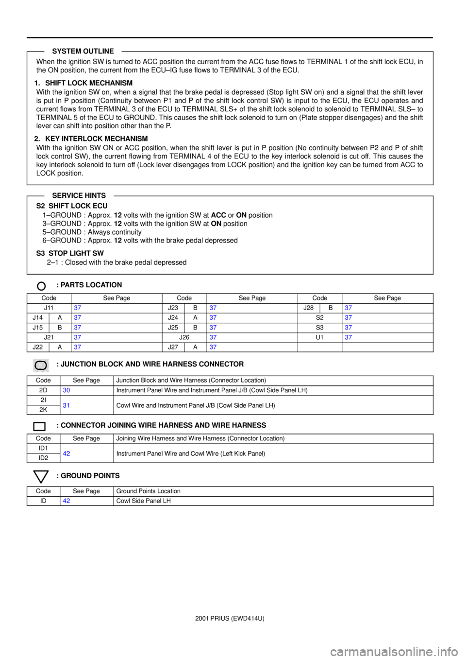
When the ignition SW is turned to ACC position the current from the ACC fuse flows to TERMINAL 1 of the shift lock ECU, in
the ON position, the current from the ECU±IG fuse flows to TERMINAL 3 of the ECU.
1. SHIFT LOCK MECHANISM
With the ignition SW on, when a signal that the brake pedal is depressed (Stop light SW on) and a signal that the shift lever
is put in P position (Continuity between P1 and P of the shift lock control SW) is input to the ECU, the ECU operates and
current flows from TERMINAL 3 of the ECU to TERMINAL SLS+ of the shift lock solenoid to solenoid to TERMINAL SLS± to
TERMINAL 5 of the ECU to GROUND. This causes the shift lock solenoid to turn on (Plate stopper disengages) and the shift
lever can shift into position other than the P.
2. KEY INTERLOCK MECHANISM
With the ignition SW ON or ACC position, when the shift lever is put in P position (No continuity between P2 and P of shift
lock control SW), the current flowing from TERMINAL 4 of the ECU to the key interlock solenoid is cut off. This causes the
key interlock solenoid to turn off (Lock lever disengages from LOCK position) and the ignition key can be turned from ACC to
LOCK position.
S2 SHIFT LOCK ECU
1±GROUND : Approx. 12 volts with the ignition SW at ACC or ON position
3±GROUND : Approx. 12 volts with the ignition SW at ON position
5±GROUND : Always continuity
6±GROUND : Approx. 12 volts with the brake pedal depressed
S3 STOP LIGHT SW
2±1 : Closed with the brake pedal depressed
: PARTS LOCATION
CodeSee PageCodeSee PageCodeSee Page
J1137J23B37J28B37
J14A37J24A37S237
J15B37J25B37S337
J2137J2637U137
J22A37J27A37
������ ���: JUNCTION BLOCK AND WIRE HARNESS CONNECTOR
CodeSee PageJunction Block and Wire Harness (Connector Location)
2D30Instrument Panel Wire and Instrument Panel J/B (Cowl Side Panel LH)
2I31Cowl Wire and Instrument Panel J/B (Cowl Side Panel LH)2K31Cowl Wire and Instrument Panel J/B (Cowl Side Panel LH)
: CONNECTOR JOINING WIRE HARNESS AND WIRE HARNESS
CodeSee PageJoining Wire Harness and Wire Harness (Connector Location)
ID142Instrument Panel Wire and Cowl Wire (Left Kick Panel)ID242Instrument Panel Wire and Cowl Wire (Left Kick Panel)
: GROUND POINTS
CodeSee PageGround Points Location
ID42Cowl Side Panel LH
SYSTEM OUTLINE
SERVICE HINTS
Page 142 of 1943

2001 PRIUS (EWD414U)
WIRELESS DOOR LOCK CONTROL
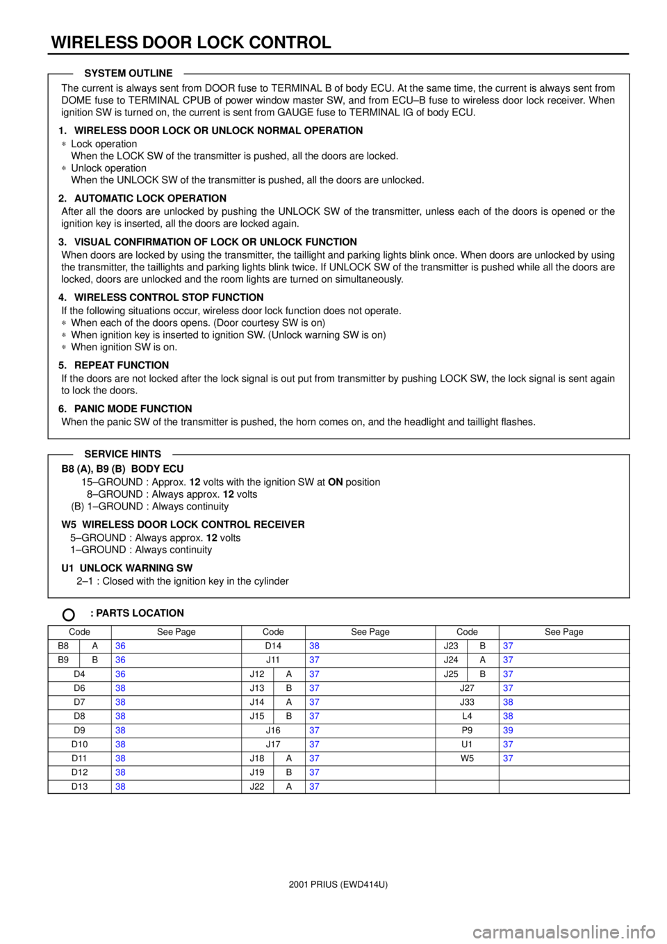
The current is always sent from DOOR fuse to TERMINAL B of body ECU. At the same time, the current is always sent from
DOME fuse to TERMINAL CPUB of power window master SW, and from ECU±B fuse to wireless door lock receiver. When
ignition SW is turned on, the current is sent from GAUGE fuse to TERMINAL IG of body ECU.
1. WIRELESS DOOR LOCK OR UNLOCK NORMAL OPERATION
*Lock operation
When the LOCK SW of the transmitter is pushed, all the doors are locked.
*Unlock operation
When the UNLOCK SW of the transmitter is pushed, all the doors are unlocked.
2. AUTOMATIC LOCK OPERATION
After all the doors are unlocked by pushing the UNLOCK SW of the transmitter, unless each of the doors is opened or the
ignition key is inserted, all the doors are locked again.
3. VISUAL CONFIRMATION OF LOCK OR UNLOCK FUNCTION
When doors are locked by using the transmitter, the taillight and parking lights blink once. When doors are unlocked by using
the transmitter, the taillights and parking lights blink twice. If UNLOCK SW of the transmitter is pushed while all the doors are
locked, doors are unlocked and the room lights are turned on simultaneously.
4. WIRELESS CONTROL STOP FUNCTION
If the following situations occur, wireless door lock function does not operate.
*When each of the doors opens. (Door courtesy SW is on)
*When ignition key is inserted to ignition SW. (Unlock warning SW is on)
*When ignition SW is on.
5. REPEAT FUNCTION
If the doors are not locked after the lock signal is out put from transmitter by pushing LOCK SW, the lock signal is sent again
to lock the doors.
6. PANIC MODE FUNCTION
When the panic SW of the transmitter is pushed, the horn comes on, and the headlight and taillight flashes.
B8 (A), B9 (B) BODY ECU
15±GROUND : Approx. 12 volts with the ignition SW at ON position
8±GROUND : Always approx. 12 volts
(B) 1±GROUND : Always continuity
W5 WIRELESS DOOR LOCK CONTROL RECEIVER
5±GROUND : Always approx. 12 volts
1±GROUND : Always continuity
U1 UNLOCK WARNING SW
2±1 : Closed with the ignition key in the cylinder
: PARTS LOCATION
CodeSee PageCodeSee PageCodeSee Page
B8A36D1438J23B37
B9B36J1137J24A37
D436J12A37J25B37
D638J13B37J2737
D738J14A37J3338
D838J15B37L438
D938J1637P939
D1038J1737U137
D1138J18A37W537
D1238J19B37
D1338J22A37
SYSTEM OUTLINE
SERVICE HINTS
Page 155 of 1943
2001 PRIUS (EWD414U)
A 17
IF
R
G
G
R GR BR
87
CF CF
F
CCENTER
CLUSTER SW C 7
GNDJUNCTION
CONNECTOR J26 M 7 , C
MULTI DISPLAYB M 5 , M 6A
AN 3, N 2 B
NAVIGATION ECU IJ1 17 IJ118 IJ119 IJ120
B 7
G3B B1
BVRB 6
VG B 7
R
B 3
G
B 1
Y
A 5
IJ1 3
A 52B 7
2A 6
A 13 B110A
GAUGE FROM POWER SOURCE SYSTEM (
SEE PAGE 50)
2C 3
25 13
IJ1 5A 14REV
R
G
Y
V±W V±W
V±W V±W
L
W± G
R±L R±B
R±B
R±BBR BR
COMBINATION METERB C10 , C11A 10 9
BACK±UP
LIGHT
RELAY B 5
RADIO AND
PLAYER R 4C 6
A 3A10
(
SHIELDED) (
SHIELDED)
SPDR±L
IJ1 21
BR
15 IJ1
8B
SYNCB 8
B B
A 14
IH 2A7
2B6
L
BR TX± TX+
GND1
G SYNC B VR SPD TX+ TX±
TX+ TX± A G
A GAG J27
JUNCTION
CONNECTORA
A DA D
J27
JUNCTION
CONNECTORA
Page 165 of 1943

2001 PRIUS (EWD414U)
SRS
NOTICE: When inspecting or repairing the SRS, perform the operation in accordance with the following precautionary
instructions and the procedure and precautions in the Repair Manual for the applicable model year.
�Malfunction symptoms of the SRS are difficult to confirm, so the DTCs become the most important source of information
when troubleshooting. When troubleshooting the SRS, always inspect the DTCs before disconnecting the battery.
�Work must be started after 90 seconds from when the ignition switch is turned to the ºLOCKº position and the
negative (±) terminal cable is disconnected from the battery.
(The SRS is equipped with a back±up power source so that if work is started within 90 seconds from
disconnecting the negative (±) terminal cable of the battery, the SRS may be deployed.)
�When the negative (±) terminal cable is disconnected from the battery, the memory of the clock and audio system will be
canceled. So before starting work, make a record of the contents memorized in the audio memory system. When work is
finished, reset the audio systems as they were before and adjust the clock. To avoid erasing the memory in each
memory system, never use a back±up power supply from outside the vehicle.
�Before repairs, remove the airbag sensor if shocks are likely to be applied to the sensor during repairs.
�Do not expose the steering wheel pad, front passenger airbag assembly, side airbag assembly, seat belt pretensioner,
airbag sensor assembly or side airbag sensor directly to hot air or flames.
�Even in cases of a minor collision where the SRS does not deploy, the steering wheel pad, front passenger airbag
assembly, side airbag assembly, seat belt pretensioner, airbag sensor assembly and side airbag sensor assembly
should be inspected.
�Never use SRS parts from another vehicle. When replacing parts, replace them with new parts.
�Never disassemble and repair the steering wheel pad, front passenger airbag assembly, side airbag assembly, seat belt
pretensioner, airbag sensor assembly or side airbag sensor assembly in order to reuse it.
�If the steering wheel pad, front passenger airbag assembly, side airbag assembly, seat belt pretensioner, airbag sensor
assembly or side airbag sensor assembly has been dropped, or if there are cracks, dents or other defects in the case,
bracket or connector, replace them with new ones.
�Use a volt/ohmmeter with high impedance (10 kW/V minimum) for troubleshooting the system's electrical circuits.
�Information labels are attached to the periphery of the SRS components. Follow the instructions on the notices.
�After work on the SRS is completed, perform the SRS warning light check.
�If the vehicle is equipped with a mobile communication system, refer to the precaution in the IN section of the Repair
Manual.
Page 167 of 1943

2001 PRIUS (EWD414U)
B 20 B 9 B 26 B 1510A
ACC FROM POWER SOURCE SYSTEM (
SEE PAGE 50)
2D 2
2A 9 2B 4
2E 1
B 3
21216 13 7
FRONT AIRBAG SENSOR
RH F 2
FRONT AIRBAG SENSOR
LH F 1DATA LINK
CONNECTOR 3 D 2
AIRBAG SENSOR ASSEMBLYB A17 , A18AC, A19 AB TC SIL
W±R
BR
B±W
BR±W W±R
BR
B±Y L
GR±R
LA
+SL ±SL +SR ±SRB 12
SIL E E
B 19
JUNCTION
CONNECTOR J26 P±B
WP±B
W
B±Y
TC
IL1 3IL14
B±W
BR±W
B D
A EA 11
2K 8
ID A
BUCKLE SW
LH B20G±O W± B
W±B
LBE+
A A
JUNCTION
CONNECTOR J29
JUNCTION CONNECTORB J22 A , J23
JUNCTION
CONNE CTOR J11
G±O
IJ1 11
W±B
IL1 2 IL1 1A C
B C
GR± R
B A 14 A 16
B5
B
GR± R L
JUNCTION
CONNECTORB J27 A , J28
SRS WARNING LIGHT
[COMB. METER]B C10 , C11A
JUNCTION
CONNECTOR J26
2D 8
L
A A
B C
JUNCTION
CONNECTORB J22 A , J23
1 2
2E 3B 28
W±B
E2
C 8RBE+
G±O
* 1 : W/ SIDE AIRBAGS
IJ1 9
B AA AAA
IJ1 10B 27E1
W±B
IH
W± B
2A 7
2B 6
1 3
3 2
BRP±L P±L W± B W±B
W± B W±B
W±B
W± B
JUNCTION
CONNECTORB J24 A , J25
BUCKLE SW RH AND
SEAT BELT WARNING
OCCUPANT DETECTION SENSOR B21
BODY ECU B 9
Page 174 of 1943
2001 PRIUS (EWD414U)
ABS
2A 7
2B 6 B 18 B2
A 10 9A10A
GAUGE FROM POWER SOURCE SYSTEM (
SEE PAGE 50)
2A 5
22 A
A 14
IH B 3B10 B4
ID1 3 ID1 1 ID1 2
B±W
V±R
V±R
B±W
L L L L
GR±B GR GR
GR±LL BRGR±G W P±B P±B
WP±B
W
GR±GW±LP±B
GR±G
GR± B CE B
13 7 1414
11 11B 2
B 3
44 13
EA EA
DATA LINK CONNECTOR 3 D 2 JUNCTION
CONNECTOR J16
COMBINATION METERB C10 , C11A BRAKE ECUB B10 , B11AC, B12 D, B13
TC D/G TSWA SP1
ENGINE CONTROL
MODULE E10 A/C AMPLIFIER A 7
GATEWAY ECU G 1
MP2+ MPD1 MPX+ MPD2 MPX± MPX1
MPX2
MPX+GR±L
TC SIL TS2K 2
B 5
R±Y
BRL
R±Y
4
PKB 15A
STOP
2K 9
R±B
1 2
B 1
STPSTOP
LIGHT SW S 3
G± W G± W
JUNCTION
CONNECTOR J26
JUNCTION
CONNECTOR J22
CEB
BODY ECUB 8
A ABS
BRAKE
A 16
A 15
IP1 1IP12 A E
A EJUNCTION
CONNECTORJ14 A