Page 1512 of 1943
A13908
A13938
A13909
I18009
A13932
EM±54
± ENGINE MECHANICALENGINE UNIT
2001 PRIUS (RM778U)
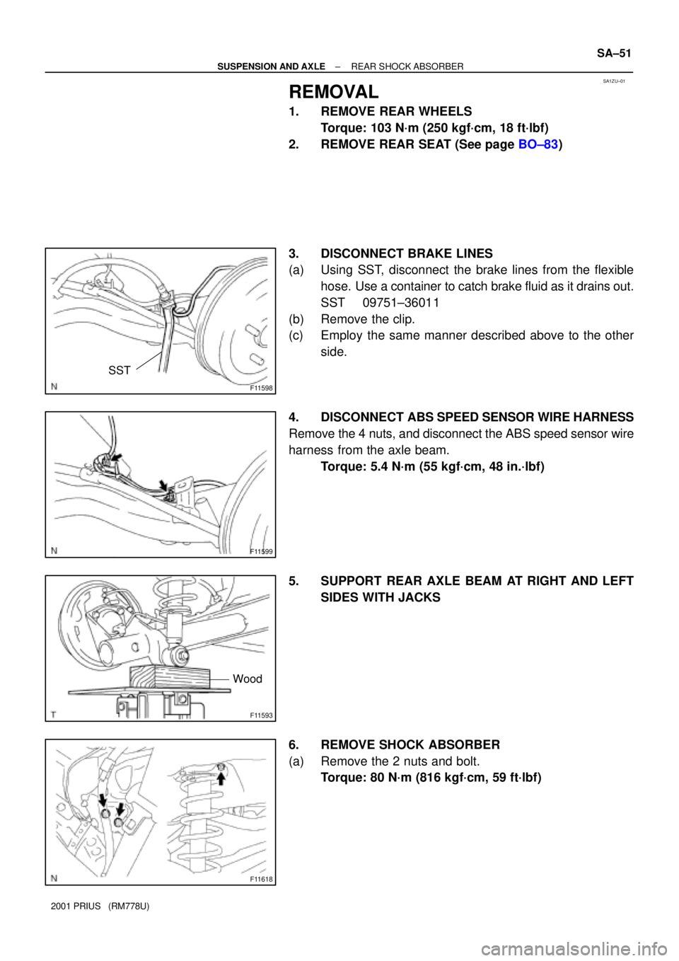
13. DISCONNECT SHIFT LEVER CABLE
14. REMOVE BRAKE RESERVOIR TANK
(a) Disconnect the brake fluid level sensor connector.
(b) Remove the 2 bolts and remove the reservoir tank and
suspend it.
15. DISCONNECT ENGINE WIRE FROM CABIN
(a) Remove the ECM (See page SF±63).
(b) Disconnect the grommet from the cowl panel, and pull out
the engine wire.
16. REMOVE J/B NO. 1 FROM RH FENDER APRON
17. DISCONNECT FUEL TUBE
Disconnect the fuel tube from the fuel pump.
18. REMOVE DRIVE BELT
19. REMOVE ENGINE UNDER COVERS
20. REMOVE A/C COMPRESSER
(a) Disconnect the A/C compresser connector.
(b) Remove the 4 bolts and disconnect the A/C compresser
from the engine.
HINT:
Suspend the A/C compresser securely.
21. DISCONNECT INTERMEDIATE EXTENSION FROM
STEERING ASSEMBLY (See page SR±6)
22. REMOVE EXHAUST PIPE
(a) Disconnect the heated oxygen sensor from the exhaust
pipe.
(b) Remove the 2 springs and 3 bolts.
(c) Disconnect the 2 O±rings, and remove the exhaust pipe
and 2 gaskets.
Page 1517 of 1943
A13939
I18009
A13909
A13938
EM±60
± ENGINE MECHANICALENGINE UNIT
2001 PRIUS (RM778U)
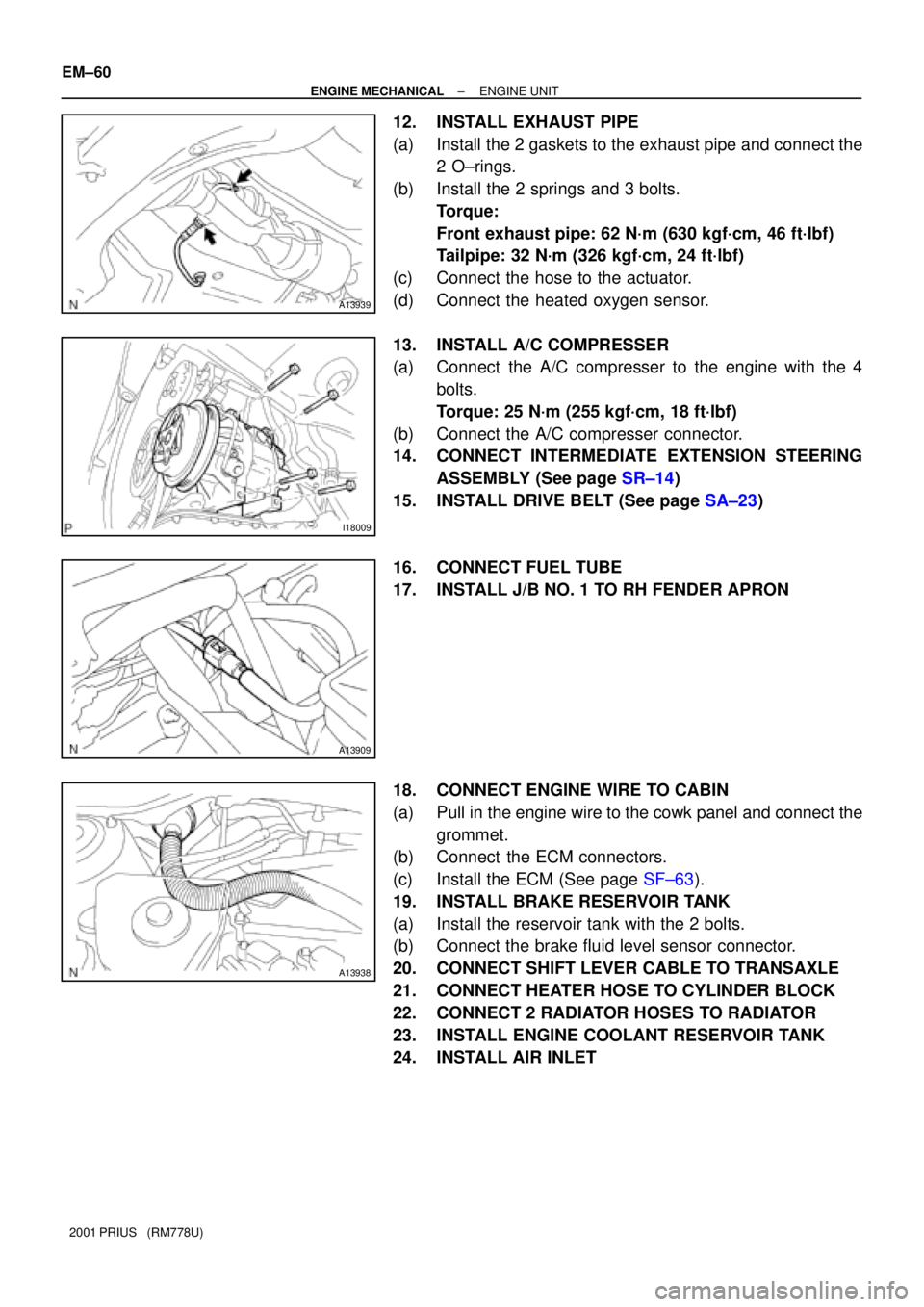
12. INSTALL EXHAUST PIPE
(a) Install the 2 gaskets to the exhaust pipe and connect the
2 O±rings.
(b) Install the 2 springs and 3 bolts.
Torque:
Front exhaust pipe: 62 N´m (630 kgf´cm, 46 ft´lbf)
Tailpipe: 32 N´m (326 kgf´cm, 24 ft´lbf)
(c) Connect the hose to the actuator.
(d) Connect the heated oxygen sensor.
13. INSTALL A/C COMPRESSER
(a) Connect the A/C compresser to the engine with the 4
bolts.
Torque: 25 N´m (255 kgf´cm, 18 ft´lbf)
(b) Connect the A/C compresser connector.
14. CONNECT INTERMEDIATE EXTENSION STEERING
ASSEMBLY (See page SR±14)
15. INSTALL DRIVE BELT (See page SA±23)
16. CONNECT FUEL TUBE
17. INSTALL J/B NO. 1 TO RH FENDER APRON
18. CONNECT ENGINE WIRE TO CABIN
(a) Pull in the engine wire to the cowk panel and connect the
grommet.
(b) Connect the ECM connectors.
(c) Install the ECM (See page SF±63).
19. INSTALL BRAKE RESERVOIR TANK
(a) Install the reservoir tank with the 2 bolts.
(b) Connect the brake fluid level sensor connector.
20. CONNECT SHIFT LEVER CABLE TO TRANSAXLE
21. CONNECT HEATER HOSE TO CYLINDER BLOCK
22. CONNECT 2 RADIATOR HOSES TO RADIATOR
23. INSTALL ENGINE COOLANT RESERVOIR TANK
24. INSTALL AIR INLET
Page 1673 of 1943
SA1ZU±01
F11598
SST
F11599
F11593
Wood
F11618
± SUSPENSION AND AXLEREAR SHOCK ABSORBER
SA±51
2001 PRIUS (RM778U)
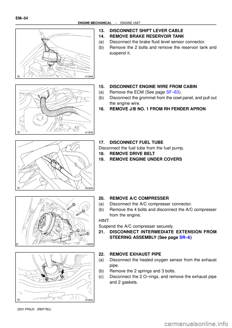
REMOVAL
1. REMOVE REAR WHEELS
Torque: 103 N´m (250 kgf´cm, 18 ft´lbf)
2. REMOVE REAR SEAT (See page BO±83)
3. DISCONNECT BRAKE LINES
(a) Using SST, disconnect the brake lines from the flexible
hose. Use a container to catch brake fluid as it drains out.
SST 09751±36011
(b) Remove the clip.
(c) Employ the same manner described above to the other
side.
4. DISCONNECT ABS SPEED SENSOR WIRE HARNESS
Remove the 4 nuts, and disconnect the ABS speed sensor wire
harness from the axle beam.
Torque: 5.4 N´m (55 kgf´cm, 48 in.´lbf)
5. SUPPORT REAR AXLE BEAM AT RIGHT AND LEFT
SIDES WITH JACKS
6. REMOVE SHOCK ABSORBER
(a) Remove the 2 nuts and bolt.
Torque: 80 N´m (816 kgf´cm, 59 ft´lbf)
Page 1677 of 1943

BR0PX±07
BR±2
± BRAKETROUBLESHOOTING
1517 Author�: Date�:
2001 PRIUS (RM778U)
TROUBLESHOOTING
PROBLEM SYMPTOMS TABLE
Use the table below to help you find the cause of the problem. The numbers indicate the priority of the likely
cause of the problem. Check each part in order. If necessary, replace these parts.
SymptomSuspect AreaSee page
Low pedal or spongy pedal
5. Fluid leaks for brake system
6. Air in brake system
7. Piston seals (Worn or damaged)
8. Master cylinder (Faulty)
9. Hydraulic brake booster (Faulty)DI±451
BR±4
BR±26
BR±32
BR±16
BR±42
Brake drag
1. Brake pedal freeplay (Minimum)
2. Parking brake pedal travel (Out of adjustment)
3. Parking brake wire (Sticking)
4. Pad or lining (Cracked or distorted)
5. Piston (Stuck)
6. Piston (Frozen)
7. Tension or return spring (Faulty)
8. Hydraulic brake booster (Faulty)BR±7
BR±9
±
BR±23
BR±32
BR±26
BR±32
BR±26
BR±32
BR±32
BR±42
Brake pull
1. Piston (Stuck)
2. Pad or lining (Cracked or distorted)
3. Piston (Frozen)
4. Disc or drum (Scored)
5. Pad or lining (Cracked or distorted)
6. Hydraulic brake booster (Faulty)BR±26
BR±32
BR±23
BR±32
BR±26
BR±32
BR±26
BR±32
BR±23
BR±32
BR±42
Hard pedal but brake inefficient
1. Fluid leaks for brake system
2. Air in brake system
3. Pad or lining (Worn)
4. Pad or lining (Cracked or distorted)
5. Pad or lining (Oily)
6. Pad or lining (Glazed)
7. Disc or drum (Scored)
8. Hydraulic brake booster (Faulty)DI±451
BR±4
BR±23
BR±32
BR±23
BR±32
BR±23
BR±32
BR±23
BR±32
BR±26
BR±32
BR±42
Page 1678 of 1943
± BRAKETROUBLESHOOTING
BR±3
1518 Author�: Date�:
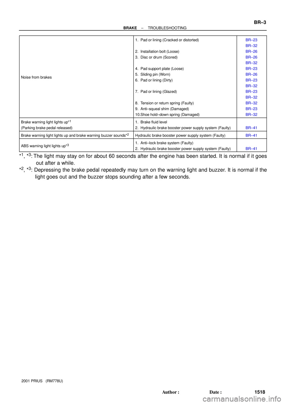
2001 PRIUS (RM778U) Noise from brakes
1. Pad or lining (Cracked or distorted)
2. Installation bolt (Loose)
3. Disc or drum (Scored)
4. Pad support plate (Loose)
5. Sliding pin (Worn)
6. Pad or lining (Dirty)
7. Pad or lining (Glazed)
8. Tension or return spring (Faulty)
9. Anti±squeal shim (Damaged)
10.Shoe hold±down spring (Damaged)BR±23
BR±32
BR±26
BR±26
BR±32
BR±23
BR±26
BR±23
BR±32
BR±23
BR±32
BR±32
BR±23
BR±32
Brake warning light lights up*1
(Parking brake pedal released)
1. Brake fluid level
2. Hydraulic brake booster power supply system (Faulty)
BR±41
Brake warning light lights up and brake warning buzzer sounds*2Hydraulic brake booster power supply system (Faulty)BR±41
ABS warning light lights up*31. Anti±lock brake system (Faulty)
2. Hydraulic brake booster power supply system (Faulty)
BR±41
*1, *3: The light may stay on for about 60 seconds after the engine has been started. It is normal if it goes
out after a while.
*
2, *3: Depressing the brake pedal repeatedly may turn on the warning light and buzzer. It is normal if the
light goes out and the buzzer stops sounding after a few seconds.
Page 1679 of 1943

BR1J6±01
BR±4
± BRAKEBRAKE FLUID
1519 Author�: Date�:
2001 PRIUS (RM778U)
BRAKE FLUID
BLEEDING
HINT:
�If any work is done on the brake system or if air in the
brake lines is suspected, bleed the air from the system.
�When bleeding, keep the amount of the fluid within the
line of reservoir between Min. and Max.
NOTICE:
�Do not let brake fluid remain on painted surfaces.
Wash it off immediately.
�With the reservoir cap removed, when depressing the
brake pedal, the fluid will spray.
1. FILL RESERVOIR WITH BRAKE FLUID
Fluid: SAE J1703 or FMVSS NO. 116 DOT3
2. RELEASE PRESSURE FROM POWER SUPPLY SYS-
TEM
HINT:
If the hydraulic brake booster has been disassembled, discon-
nect the brake line from the hydraulic brake booster or if the res-
ervoir becomes empty, bleed the hydraulic brake booster.
(a) Turn the ignition switch OFF, depress the brake pedal
more than 40 times.
(b) Turn the ignition switch ON, check that the pump stops af-
ter 30 to 40 seconds.
NOTICE:
When the pump does not stop, repeat step (a) and (b) again.
3. BLEED AIR
(a) Turning the ignition switch OFF, bleed the right and left
front brake caliper.
HINT:
Perform air bleeding for each wheel, depress the brake pedal
more than 20 times or more for each.
(b) Turning the ignition switch ON, check that the pump motor
stops.
(c) Fully open the bleeder plug of the right or left rear brake
cylinder and drain the fluid while depressing the brake
pedal for 3 seconds.
HINT:
�Perform air bleeding for both wheels on the right or left
side and then do the same on the other side.
�It is not necessary to depress the pedal continuously, as
brake fluid flows out by first depressing.
(d) Release the brake pedal and wait until the pump motor
stops.
(e) Repeat step (c) and (d) 7 times or more.
(f) Tighten the bleeder plug of the rear brake cylinder.
Torque: 8.5 N´m (87 kgf´cm, 75 in.´lbf)
(g) While depressing the brake pedal, let air out from the rear
brake cylinder mentioned in (f).
Page 1680 of 1943
F12396
T
TOYOTA
Hand±held Tester
DLC3
± BRAKEBRAKE FLUID
BR±5
1520 Author�: Date�:
2001 PRIUS (RM778U)
HINT:
�Hold the brake pedal depressed, and it is not necessary
to repeat depressing of the pedal.
�Do not continuously drain the fluid from the bleeder plug
for more than 3 seconds.
�When closing the bleeder plug, wait until the pump motor
stops if it is operated.
�Repeat the procedure until air is completely removed.
(h) Perform step (c) to (g) on the other rear brake cylinder.
(i) With the ignition switch ON, check that the pump motor is
stopped.
(j) Fully the bleeder plug of the front left brake cylinder and
drain the fluid while depressing the brake pedal for 3 se-
conds.
(k) Release the brake pedal and wait until the pump motor
stops.
(l) Repeat step (j) and (k) 4 times.
(m) Tighten the bleeder plug of the front left brake cylinder.
Torque: 8.5 N´m (87 kgf´cm, 75 in.´lbf)
(n) While depressing the brake pedal, let air out from the front
left brake cylinder.
HINT:
�Hold the brake pedal depressed, and it is not necessary
to repeat depressing of the pedal.
�Do not continuously drain the fluid from the bleeder plug
for more than 3 seconds.
�When closing the bleeder plug, wait until the pump motor
stops if it is operated.
�Repeat the procedure until air is completely removed.
(o) Check that the pump motor is stopped.
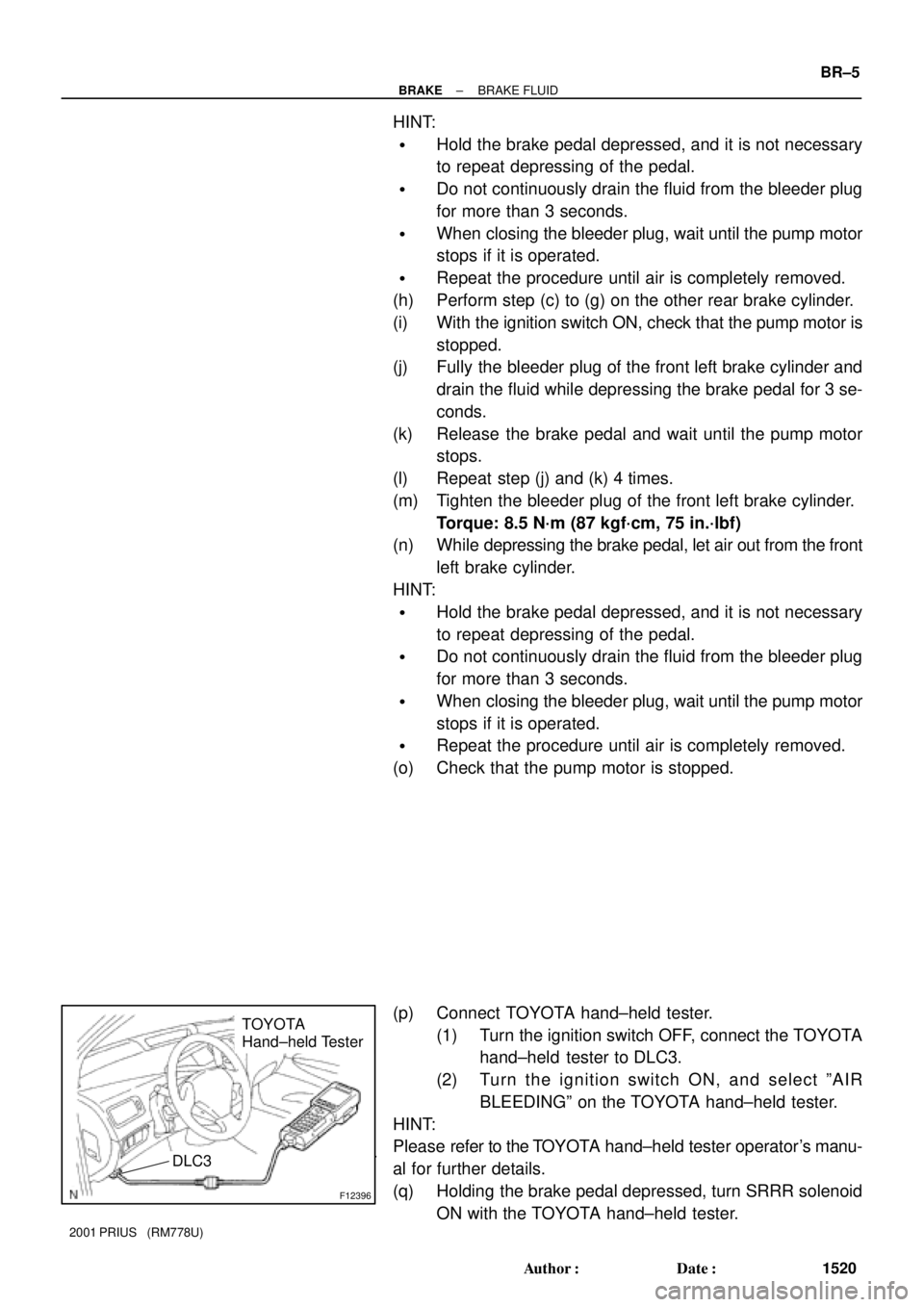
(p) Connect TOYOTA hand±held tester.
(1) Turn the ignition switch OFF, connect the TOYOTA
hand±held tester to DLC3.
(2) Turn the ignition switch ON, and select ºAIR
BLEEDINGº on the TOYOTA hand±held tester.
HINT:
Please refer to the TOYOTA hand±held tester operator's manu-
al for further details.
(q) Holding the brake pedal depressed, turn SRRR solenoid
ON with the TOYOTA hand±held tester.
Page 1681 of 1943
BR±6
± BRAKEBRAKE FLUID
1521 Author�: Date�:
2001 PRIUS (RM778U)
HINT:
Do not keep the solenoid activated for 2 seconds, or more. Al-
low an interval of 20 seconds, or more if activating it continuous-
ly.
(r) Turn the SRRR solenoid OFF with the TOYOTA hand±
held tester, and release the brake pedal.
(s) Check that the pump motor stops after 20 seconds.
(t) Repeat step (q) to (s) 3 times.
(u) Turn the ignition switch OFF, and disconnect the TOYOTA
hand±held tester from DLC3.
(v) Clear the DTC (See page DI±353).
HINT:
�Diagnosis codes are erased with the shift lever in P range.
�After erasing, turn the ignition switch OFF to protect ECU.
4. CHECK FLUID LEVEL IN RESERVOIR
(a) With the ignition switch OFF, depress the brake pedal
more than 40 times.
(b) Remove the reservoir cap. Add brake fluid up to the
ºMAXº line.
Fluid: SAE J1703 or FMVSS NO. 116 DOT3