Page 1687 of 1943
F12060
± BRAKEFRONT BRAKE PAD
BR±25
2001 PRIUS (RM778U)
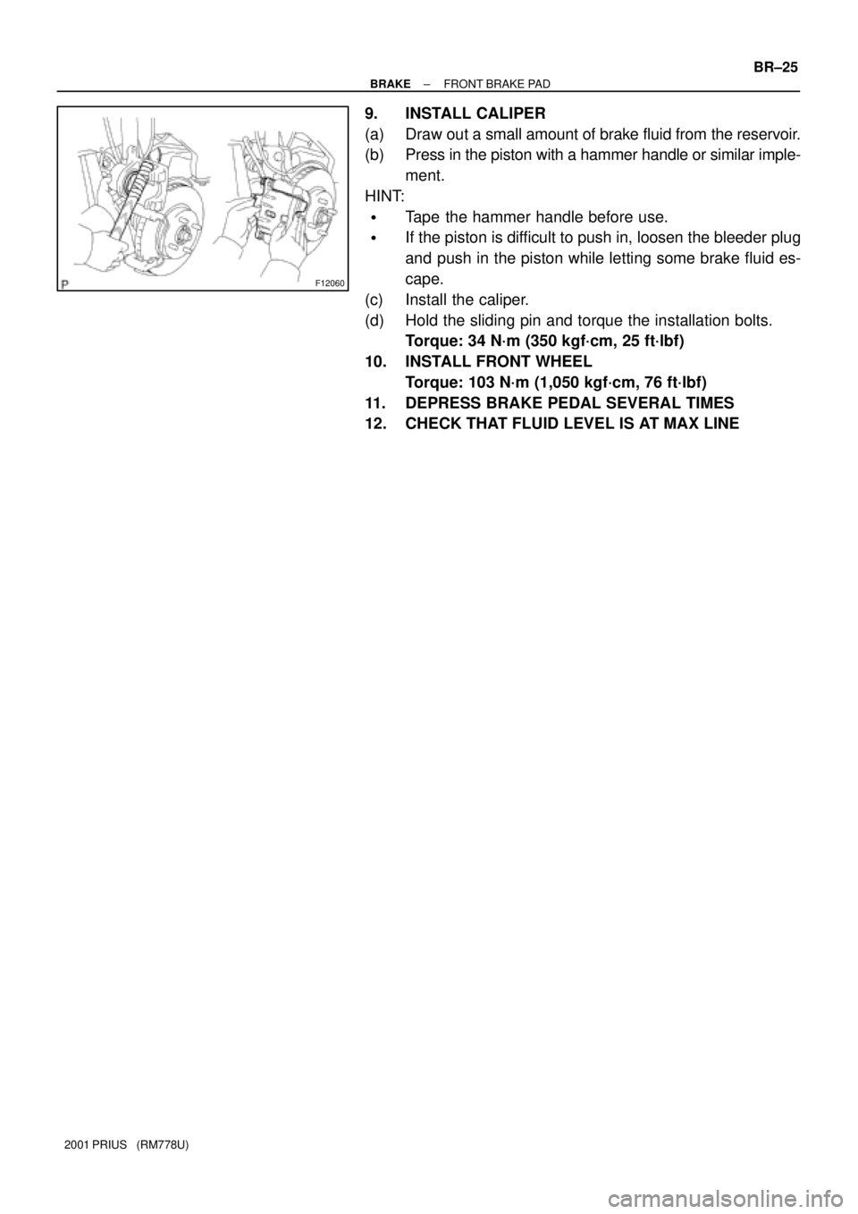
9. INSTALL CALIPER
(a) Draw out a small amount of brake fluid from the reservoir.
(b) Press in the piston with a hammer handle or similar imple-
ment.
HINT:
�Tape the hammer handle before use.
�If the piston is difficult to push in, loosen the bleeder plug
and push in the piston while letting some brake fluid es-
cape.
(c) Install the caliper.
(d) Hold the sliding pin and torque the installation bolts.
Torque: 34 N´m (350 kgf´cm, 25 ft´lbf)
10. INSTALL FRONT WHEEL
Torque: 103 N´m (1,050 kgf´cm, 76 ft´lbf)
11. DEPRESS BRAKE PEDAL SEVERAL TIMES
12. CHECK THAT FLUID LEVEL IS AT MAX LINE
Page 1689 of 1943
F09780
F12390
SST
BR±34
± BRAKEREAR DRUM BRAKE
2001 PRIUS (RM778U)
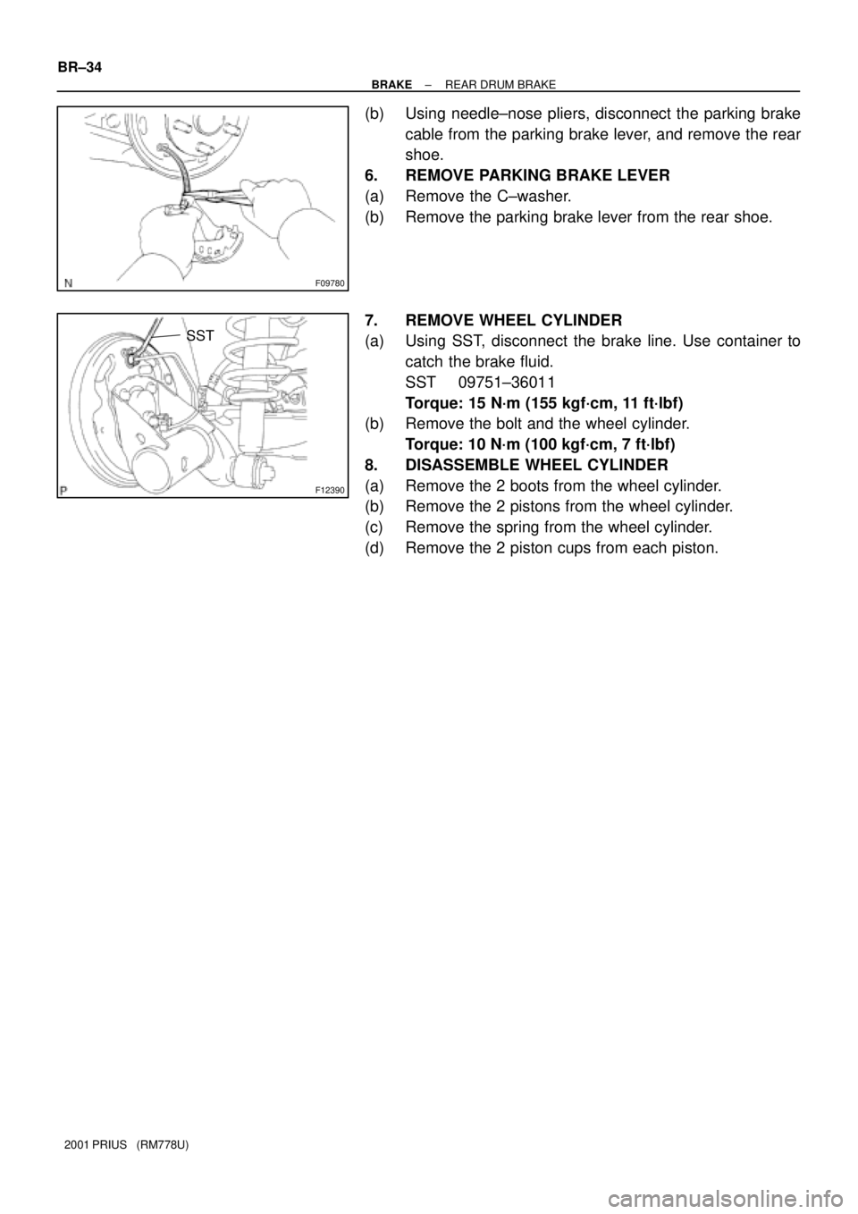
(b) Using needle±nose pliers, disconnect the parking brake
cable from the parking brake lever, and remove the rear
shoe.
6. REMOVE PARKING BRAKE LEVER
(a) Remove the C±washer.
(b) Remove the parking brake lever from the rear shoe.
7. REMOVE WHEEL CYLINDER
(a) Using SST, disconnect the brake line. Use container to
catch the brake fluid.
SST 09751±36011
Torque: 15 N´m (155 kgf´cm, 11 ft´lbf)
(b) Remove the bolt and the wheel cylinder.
Torque: 10 N´m (100 kgf´cm, 7 ft´lbf)
8. DISASSEMBLE WHEEL CYLINDER
(a) Remove the 2 boots from the wheel cylinder.
(b) Remove the 2 pistons from the wheel cylinder.
(c) Remove the spring from the wheel cylinder.
(d) Remove the 2 piston cups from each piston.
Page 1692 of 1943
BR1JJ±01
F12385
BR±44
± BRAKEHYDRAULIC BRAKE BOOSTER
2001 PRIUS (RM778U)
REMOVAL
NOTICE:
Before starting the work, make sure that the ignition switch
is OFF and depress the brake pedal more than 40 times.
HINT:
When a pressure in power supply system is released, reaction
force becomes heavy.
NOTICE:
�As high pressure is applied to the brake actuator
tube, never deform it.
�Until the work is over, do not turn the ignition switch
ON.
1. DRAW OUT FLUID WITH SYRINGE
NOTICE:
Do not let brake fluid remain on a painted surface. Wash it
off immediately.
2. REMOVE OUTER FRONT COWL TOP PANEL
(See page BO±32)
3. REMOVE RESERVOIR, BRAKE ACTUATOR HOSE,
BRAKE RESERVOIR HOSE NO. 1, NO. 2 AND RES-
ERVOIR BRACKET
(a) Disconnect the fluid level warning switch connector from
the reservoir.
(b) Remove the 2 bolts from the reservoir.
Torque: 7.5 N´m (77 kgf´cm, 66 in.´lbf)
(c) Disconnect the 3 hoses from the reservoir and remove the
reservoir and 3 hoses.
(d) Disconnect the 3 hoses from the reservoir bracket clamp.
(e) Remove the 4 bolts and reservoir bracket.
Torque: 18 N´m (184 kgf´cm, 13 ft´lbf)
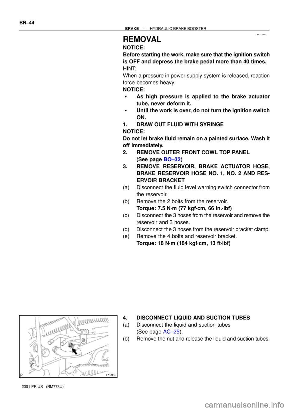
4. DISCONNECT LIQUID AND SUCTION TUBES
(a) Disconnect the liquid and suction tubes
(See page AC±25).
(b) Remove the nut and release the liquid and suction tubes.
Page 1764 of 1943
± BODY ELECTRICALTROUBLESHOOTING
BE±7
1674 Author�: Date�:
2001 PRIUS (RM778U)
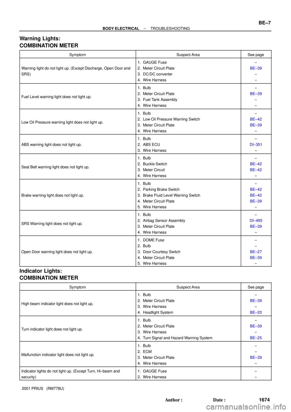
Warning Lights:
COMBINATION METER
SymptomSuspect AreaSee page
Warning light do not light up. (Except Discharge, Open Door and
SRS)
1. GAUGE Fuse
2. Meter Circuit Plate
3. DC/DC converter
4. Wire Harness±
BE±39
±
±
Fuel Level warning light does not light up.
1. Bulb
2. Meter Circuit Plate
3. Fuel Tank Assembly
4. Wire Harness±
BE±39
±
±
Low Oil Pressure warning light does not light up.
1. Bulb
2. Low Oil Pressure Warning Switch
3. Meter Circuit Plate
4. Wire Harness±
BE±42
BE±39
±
ABS warning light does not light up.
1. Bulb
2. ABS ECU
3. Wire Harness±
DI±351
±
Seat Belt warning light does not light up.
1. Bulb
2. Buckle Switch
3. Meter Circuit
4. Wire Harness±
BE±42
BE±42
±
Brake warning light does not light up.
1. Bulb
2. Parking Brake Switch
3. Brake Fluid Level Warning Switch
4. Meter Circuit Plate
5. Wire Harness±
BE±42
BE±42
BE±39
±
SRS Warning light does not light up.
1. Bulb
2. Airbag Sensor Assembly
3. Meter Circuit Plate
4. Wire Harness±
DI±495
BE±39
±
Open Door warning light does not light up.
1. DOME Fuse
2. Bulb
3. Door Courtesy Switch
4. Meter Circuit Plate
5. Wire Harness±
±
BE±27
BE±39
±
Indicator Lights:
COMBINATION METER
SymptomSuspect AreaSee page
High beam indicator light does not light up.
1. Bulb
2. Meter Circuit Plate
3. Wire Harness
4. Headlight System±
BE±39
±
BE±20
Turn indicator light does not light up.
1. Bulb
2. Meter Circuit Plate
3. Wire Harness
4. Turn Signal and Hazard Warning System±
BE±39
±
BE±25
Malfunction indicator light does not light up.
1. Bulb
2. ECM
3. Meter Circuit Plate
4. Wire Harness±
±
BE±39
±
Indicator lights do not light up. (Except Turn, Hi±beam and
security)1. GAUGE Fuse
2. Wire Harness±
±
Page 1782 of 1943
BE1VS±02
I18849
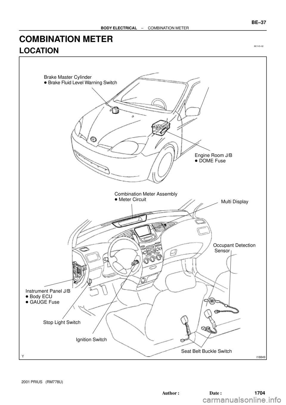
Brake Master Cylinder
� Brake Fluid Level Warning Switch
Combination Meter Assembly
� Meter Circuit
Multi Display
Ignition Switch
Instrument Panel J/B
� Body ECU
� GAUGE Fuse
Stop Light Switch
Engine Room J/B
� DOME Fuse
Seat Belt Buckle Switch
Occupant Detection
Sensor
± BODY ELECTRICALCOMBINATION METER
BE±37
1704 Author�: Date�:
2001 PRIUS (RM778U)
COMBINATION METER
LOCATION
Page 1790 of 1943
BE1217
BatteryWarning Light
Ignition
Switch
I11650
BE0044
BatteryWarning Light
Ignition
Switch
Z11183
± BODY ELECTRICALCOMBINATION METER
BE±45
2001 PRIUS (RM778U)
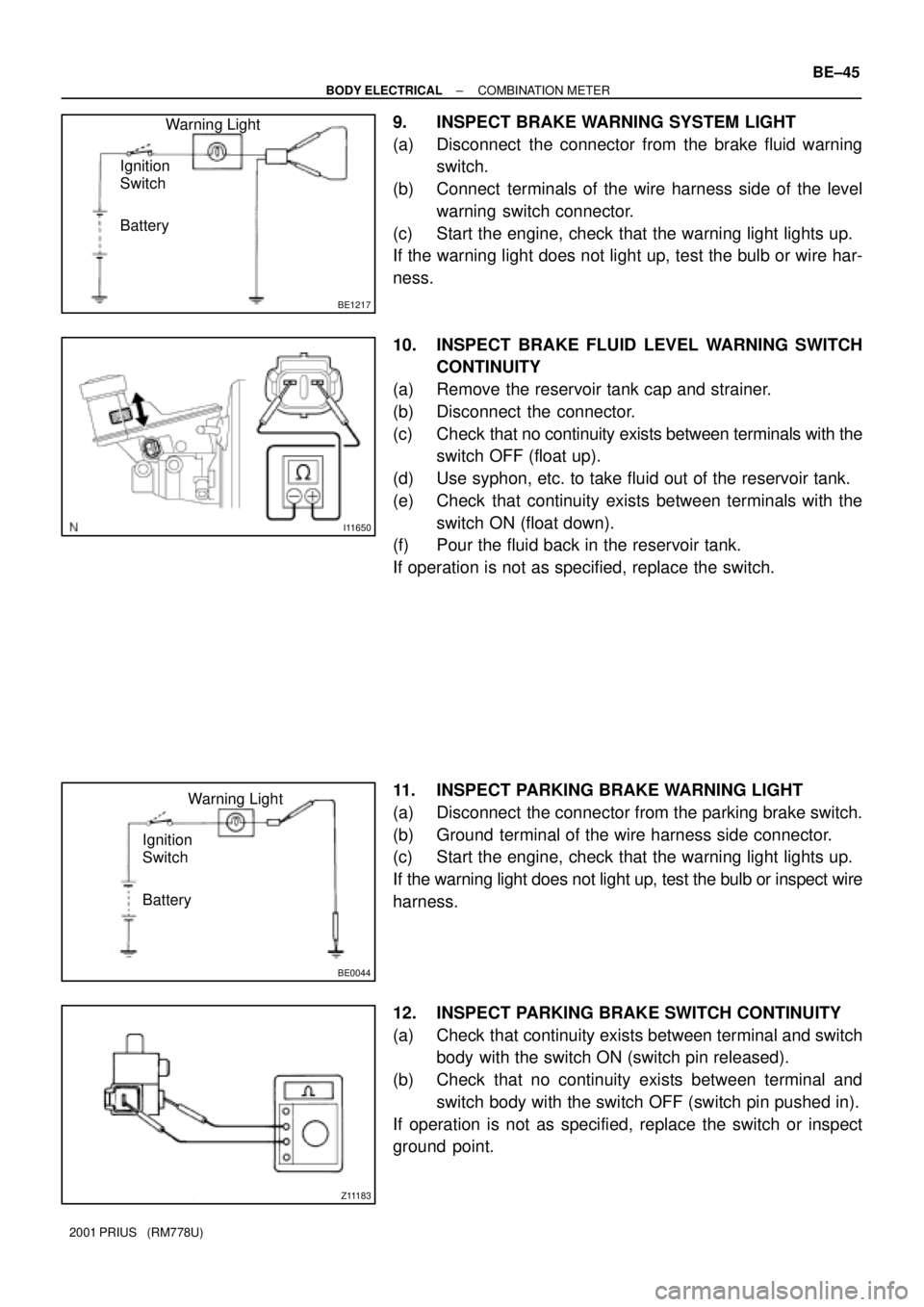
9. INSPECT BRAKE WARNING SYSTEM LIGHT
(a) Disconnect the connector from the brake fluid warning
switch.
(b) Connect terminals of the wire harness side of the level
warning switch connector.
(c) Start the engine, check that the warning light lights up.
If the warning light does not light up, test the bulb or wire har-
ness.
10. INSPECT BRAKE FLUID LEVEL WARNING SWITCH
CONTINUITY
(a) Remove the reservoir tank cap and strainer.
(b) Disconnect the connector.
(c) Check that no continuity exists between terminals with the
switch OFF (float up).
(d) Use syphon, etc. to take fluid out of the reservoir tank.
(e) Check that continuity exists between terminals with the
switch ON (float down).
(f) Pour the fluid back in the reservoir tank.
If operation is not as specified, replace the switch.
11. INSPECT PARKING BRAKE WARNING LIGHT
(a) Disconnect the connector from the parking brake switch.
(b) Ground terminal of the wire harness side connector.
(c) Start the engine, check that the warning light lights up.
If the warning light does not light up, test the bulb or inspect wire
harness.
12. INSPECT PARKING BRAKE SWITCH CONTINUITY
(a) Check that continuity exists between terminal and switch
body with the switch ON (switch pin released).
(b) Check that no continuity exists between terminal and
switch body with the switch OFF (switch pin pushed in).
If operation is not as specified, replace the switch or inspect
ground point.