2001 TOYOTA PRIUS ECO mode
[x] Cancel search: ECO modePage 698 of 1943
BE6653A10620A14040A14045
START
ON
OFFVSV for EVAP
1.2 V ON
OFF
E2
PTNK
(±) (+)
VSV for CCV
Measure
Voltage30 sec.
± DIAGNOSTICSENGINE
DI±95
2001 PRIUS (RM778U)
OK
Replace VSV and charcoal canister, and clean vacuum hoses ((1), (2) and (3) in Fig. 1 in circuit
description.
23 Check for open and short in harness and connector between EFI main relay
(Marking: EFI) and VSV for purge flow switching valve, and VSV for purge flow
switching valve and ECU (See page IN±41).
NG Repair or replace harness or connector.
OK
Check and replace ECM (See page IN±41).
24 Check fuel tank and charcoal canister.
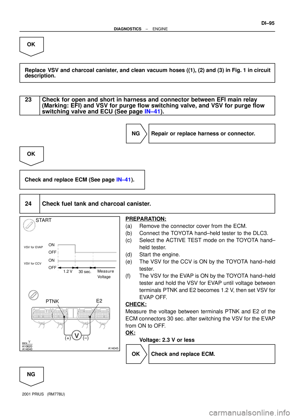
PREPARATION:
(a) Remove the connector cover from the ECM.
(b) Connect the TOYOTA hand±held tester to the DLC3.
(c) Select the ACTIVE TEST mode on the TOYOTA hand±
held tester.
(d) Start the engine.
(e) The VSV for the CCV is ON by the TOYOTA hand±held
tester.
(f) The VSV for the EVAP is ON by the TOYOTA hand±held
tester and hold the VSV for EVAP until voltage between
terminals PTNK and E2 becomes 1.2 V, then set VSV for
EVAP OFF.
CHECK:
Measure the voltage between terminals PTNK and E2 of the
ECM connectors 30 sec. after switching the VSV for the EVAP
from ON to OFF.
OK:
Voltage: 2.3 V or less
OK Check and replace ECM.
NG
Page 769 of 1943
FI7012A11860
P±G A/C Control Assembly
A8 E10522
ACTECM
± DIAGNOSTICSENGINE
DI±171
2001 PRIUS (RM778U)
A/C Cut Control Circuit
CIRCUIT DESCRIPTION
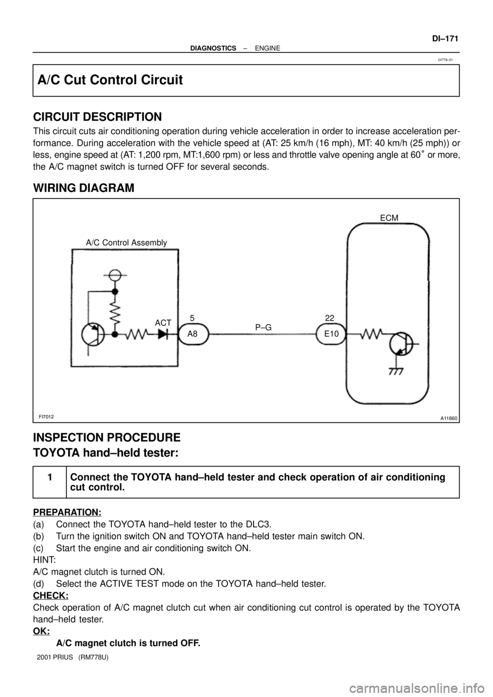
This circuit cuts air conditioning operation during vehicle acceleration in order to increase acceleration per-
formance. During acceleration with the vehicle speed at (AT: 25 km/h (16 mph), MT: 40 km/h (25 mph)) or
less, engine speed at (AT: 1,200 rpm, MT:1,600 rpm) or less and throttle valve opening angle at 60° or more,
the A/C magnet switch is turned OFF for several seconds.
WIRING DIAGRAM
INSPECTION PROCEDURE
TOYOTA hand±held tester:
1 Connect the TOYOTA hand±held tester and check operation of air conditioning
cut control.
PREPARATION:
(a) Connect the TOYOTA hand±held tester to the DLC3.
(b) Turn the ignition switch ON and TOYOTA hand±held tester main switch ON.
(c) Start the engine and air conditioning switch ON.
HINT:
A/C magnet clutch is turned ON.
(d) Select the ACTIVE TEST mode on the TOYOTA hand±held tester.
CHECK:
Check operation of A/C magnet clutch cut when air conditioning cut control is operated by the TOYOTA
hand±held tester.
OK:
A/C magnet clutch is turned OFF.
DI7T8±01
Page 784 of 1943
F12396
TOYOTA hand±held tester
DLC3
± DIAGNOSTICSHYBRID VEHICLE CONTROL SYSTEM
DI±187
2001 PRIUS (RM778U)
(d) Clear the DTC after completion of repair.
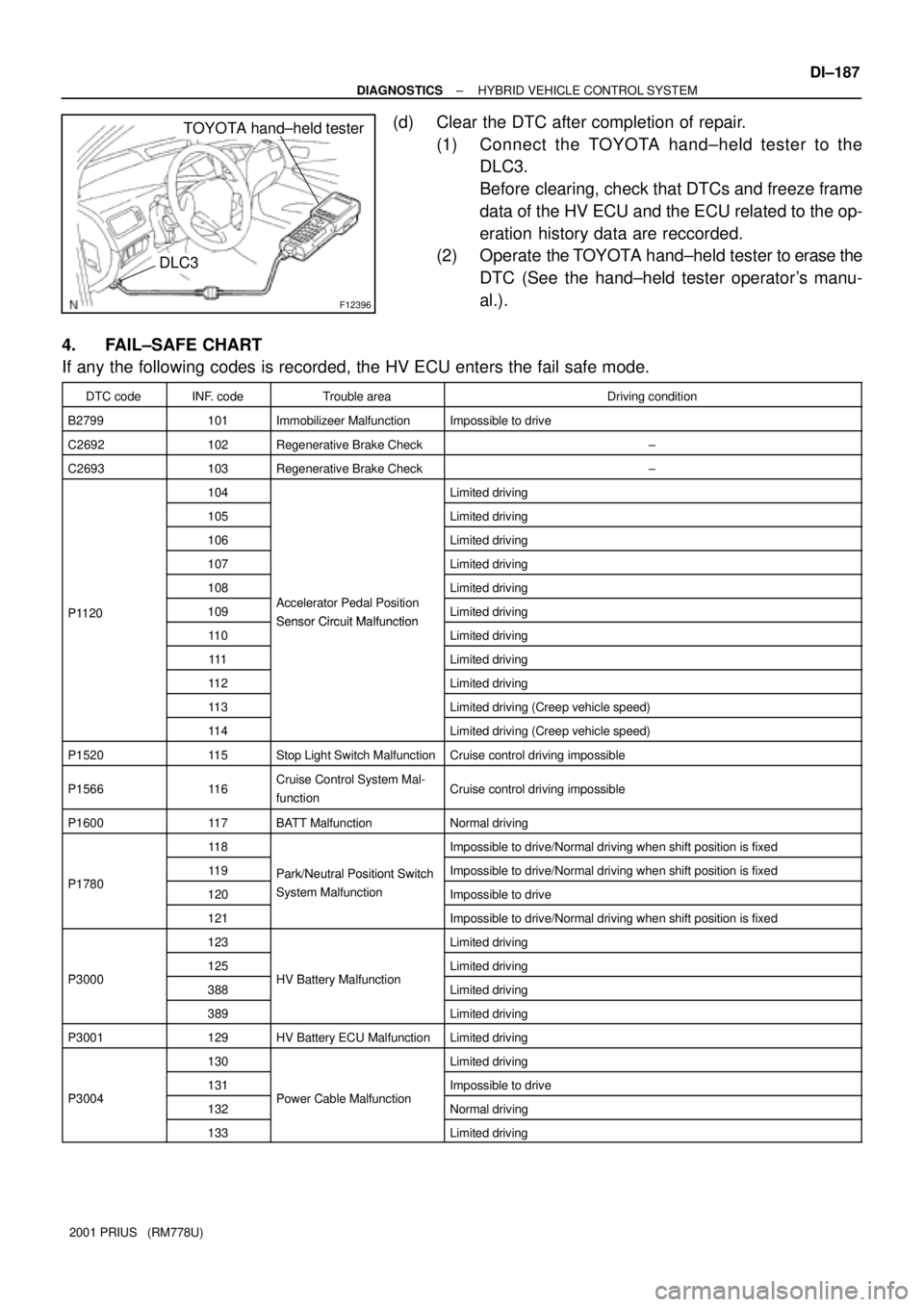
(1) Connect the TOYOTA hand±held tester to the
DLC3.
Before clearing, check that DTCs and freeze frame
data of the HV ECU and the ECU related to the op-
eration history data are reccorded.
(2) Operate the TOYOTA hand±held tester to erase the
DTC (See the hand±held tester operator's manu-
al.).
4. FAIL±SAFE CHART
If any the following codes is recorded, the HV ECU enters the fail safe mode.
DTC codeINF. codeTrouble areaDriving condition
B2799101Immobilizeer MalfunctionImpossible to drive
C2692102Regenerative Brake Check±
C2693103Regenerative Brake Check±
104Limited driving
105Limited driving
106Limited driving
107Limited driving
108Limited driving
P1120109Accelerator Pedal Position
Sensor Circuit MalfunctionLimited drivingP1120
11 0Sensor Circuit MalfunctionLimited driving
111Limited driving
11 2Limited driving
11 3Limited driving (Creep vehicle speed)
11 4Limited driving (Creep vehicle speed)
P152011 5Stop Light Switch MalfunctionCruise control driving impossible
P156611 6Cruise Control System Mal-
functionCruise control driving impossible
P160011 7BATT MalfunctionNormal driving
11 8Impossible to drive/Normal driving when shift position is fixed
P178011 9Park/Neutral Positiont SwitchImpossible to drive/Normal driving when shift position is fixedP1780120
Park/Neutral Positiont Switch
System MalfunctionImpossible to drive
121
y
Impossible to drive/Normal driving when shift position is fixed
123Limited driving
P3000125HV B tt M lf tiLimited drivingP3000388HV Battery MalfunctionLimited driving
389Limited driving
P3001129HV Battery ECU MalfunctionLimited driving
130Limited driving
P3004131PCblMlftiImpossible to driveP3004132Power Cable MalfunctionNormal driving
133Limited driving
Page 790 of 1943

± DIAGNOSTICSHYBRID VEHICLE CONTROL SYSTEM
DI±193
2001 PRIUS (RM778U)
5. CHECK FOR INTERMITTENT PROBLEMS
(a) Perform a simulation test (See page IN±41).
In the simulation test, reproduce the driving condition at the trouble occurrence according to the cus-
tomer 's comments and freeze frame data recorded with DTC, such as an opening angle of the acceler-
ator pedal, SOC, engine coolant temperature, engine rpm, and MG/1MG2 rpm and torque.
(b) Check the connector and terminal (See page IN±41).
(c) Handle the connector (See page IN±41).
6. TOYOTA HAND±HELD TESTER DISPLAY ITEMS
TOYOTA Hand±held tester displayMeasurement Item
1 BEF LATST ORNumber of operation of 1 trip before last
1 BEF LATST TRPNumber of trips before last
2 BEF LATST ORNumber of operation 2 trips before last
2 BEF LATST TRPNumber of trips 2 before last
ABNML CON BR±HVCommunication malfunction between HV ECU and brake
ACC SENSOR MAINMain accelerator sensor
ACC SENSOR SUBSub accelerator sensor
ACC TENT TRBLETentative trouble of accelerator
ACC THROTTLEAccelerator throttle
ACCEL MODEHistory of acceleration and reduction
AIR CON REQUESTAir conditioner request
AUX. BATT LOWAuxiliary battery becomes week
AUX. BATT VVoltage of auxiliary battery
BATT HIGH TEMPTemperature of the battery is too high
BATT HIGH VOLTVoltage of the battery is too high
BATT LOW BOLTVoltage of the battery is low
BATT OVER LOADBattery is overloaded
BATT SAVE RQSTRequest to save the main battery
BATTERY FULLBattery full
BRAKE TORQBrake torque
CELL TEMP±MAXHighest temperature of all battery cells
CELL TEMP±MINLowest temperature of all battery cells
CHG RESTRICTIONCharge restriction
COOLANT TEMPWater temperature
CRUISE CONTROLCondition of the cruise control
DC/DC CONV STOPDC/DC converter stop signal
DC/DC CONV STOPFactors causing DC/DC converter to stop
DC/DC STOP FACTDC/DC converter has stopped at least once
DC/DC V UNSETDC/DC voltage is unsettled
DCHG RQST SOCDischarge request to adjust SOC
DISCHAG INHIBITBattery is inhibited to discharge
Page 940 of 1943
F12396
TOYOTA
Hand±held Tester
DLC3
F09750
DLC3Tc
Ts
CG
BR3904
0.13 sec. 0.13 sec.
ON
OFF DI±360
± DIAGNOSTICSANTI±LOCK BRAKE SYSTEM WITH EBD & RBS
2001 PRIUS (RM778U)
(g) In case of using TOYOTA hand±held tester:
Clear the DTC.
(1) Hook up the TOYOTA hand±held tester to the
DLC3.
(2) Turn the ignition switch ON.
(3) Operate the TOYOTA hand±held tester to erase the
codes.
HINT:
Please refer to the TOYOTA hand±held tester operator's manu-
al for further details.
3. SENSOR SIGNAL CHECK (TEST MODE)
HINT:
If the ignition switch is turned from ON to ACC or LOCK during
test mode, DTC will be erased.
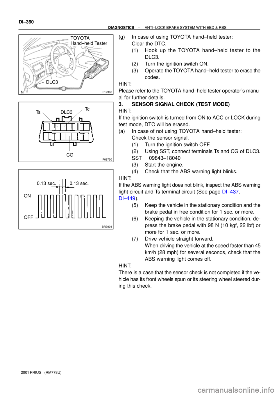
(a) In case of not using TOYOTA hand±held tester:
Check the sensor signal.
(1) Turn the ignition switch OFF.
(2) Using SST, connect terminals Ts and CG of DLC3.
SST 09843±18040
(3) Start the engine.
(4) Check that the ABS warning light blinks.
HINT:
If the ABS warning light does not blink, inspect the ABS warning
light circuit and Ts terminal circuit (See page DI±437,
DI±449).
(5) Keep the vehicle in the stationary condition and the
brake pedal in free condition for 1 sec. or more.
(6) Keeping the vehicle in the stationary condition, de-
press the brake pedal with 98 N (10 kgf, 22 lbf) or
more for 1 sec. or more.
(7) Drive vehicle straight forward.
When driving the vehicle at the speed faster than 45
km/h (28 mph) for several seconds, check that the
ABS warning light comes off.
HINT:
There is a case that the sensor check is not completed if the ve-
hicle has its front wheels spun or its steering wheel steered dur-
ing this check.
Page 993 of 1943
F12410
LOCKON
PH
PHG
H8
DI±416
± DIAGNOSTICSANTI±LOCK BRAKE SYSTEM WITH EBD & RBS
2001 PRIUS (RM778U)
4 Check pressure switch (PH).
In case of using the TOYOTA hand±held tester:
PREPARATION:
(a) Connect the TOYOTA hand±held tester to the DLC3.
(b) Turn the ignition switch ON, and push the TOYOTA hand±held tester main switch ON.
(c) Select the DATALIST mode on the TOYOTA hand±held tester.
CHECK:
Depress the brake pedal more than 40 times with the ignition switch OFF then turn the ignition switch ON
and check the pressure switch (PH) condition.
HINT:
When a pressure in power supply system is released, reaction force becomes heavy and stroke becomes
shorter.
OK:
ºOFFº turns to ºONº.
HINT:
OFF: Low pressure
ON: High pressure
In case of not using the TOYOTA hand±held tester:
PREPARATION:
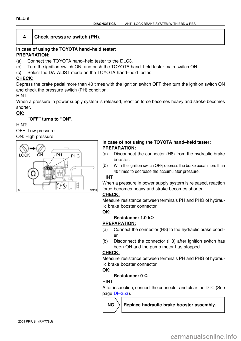
(a) Disconnect the connector (H8) from the hydraulic brake
booster.
(b)
With the ignition switch OFF, depress the brake pedal more than
40 times to decrease the accumulator pressure.
HINT:
When a pressure in power supply system is released, reaction
force becomes heavy and stroke becomes shorter.
CHECK:
Measure resistance between terminals PH and PHG of hydrau-
lic brake booster connector.
OK:
Resistance: 1.0 kW
PREPARATION:
(a) Connect the connector (H8) to the hydraulic brake boost-
er.
(b) Disconnect the connector (H8) after ignition switch has
been ON and the pump motor has stopped.
CHECK:
Measure resistance between terminals PH and PHG of hydrau-
lic brake booster connector.
OK:
Resistance: 0 W
HINT:
After inspection, connect the connector and clear the DTC (See
page DI±353).
NG Replace hydraulic brake booster assembly.
Page 994 of 1943
F12411
LOCKONPL
PLG
H9
± DIAGNOSTICSANTI±LOCK BRAKE SYSTEM WITH EBD & RBS
DI±417
2001 PRIUS (RM778U)
OK
5 Check pressure switch (PL).
In case of using TOYOTA hand±held tester:
PREPARATION:
(a) Connect the TOYOTA hand±held tester to the DLC3.
(b) Turn the ignition switch ON, and push the TOYOTA hand±held tester main switch ON.
(c) Select the DATALIST mode on the TOYOTA hand±held tester.
CHECK:
Depress the brake pedal more than 40 times with the ignition switch OFF then turn the ignition switch ON
and check the pressure switch (PL) condition.
HINT:
When a pressure in power supply system is released, reaction force becomes heavy and stroke becomes
shorter.
OK:
ºOFFº turns to ºONº.
HINT:
OFF: Low pressure
ON: High pressure
In case of not using TOYOTA hand±held tester:
PREPARATION:
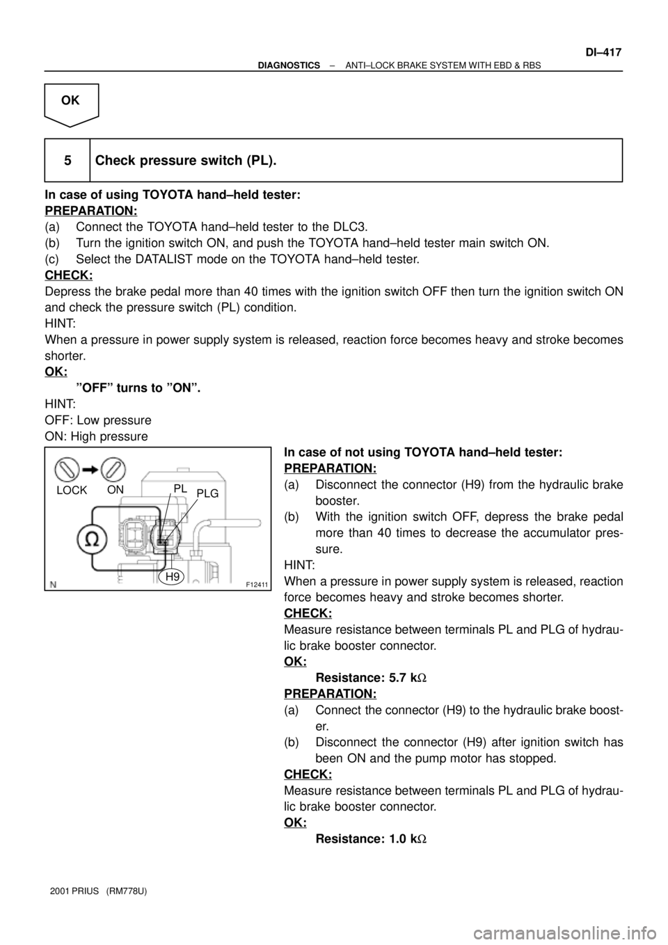
(a) Disconnect the connector (H9) from the hydraulic brake
booster.
(b) With the ignition switch OFF, depress the brake pedal
more than 40 times to decrease the accumulator pres-
sure.
HINT:
When a pressure in power supply system is released, reaction
force becomes heavy and stroke becomes shorter.
CHECK:
Measure resistance between terminals PL and PLG of hydrau-
lic brake booster connector.
OK:
Resistance: 5.7 kW
PREPARATION:
(a) Connect the connector (H9) to the hydraulic brake boost-
er.
(b) Disconnect the connector (H9) after ignition switch has
been ON and the pump motor has stopped.
CHECK:
Measure resistance between terminals PL and PLG of hydrau-
lic brake booster connector.
OK:
Resistance: 1.0 kW
Page 1328 of 1943
I15449
System check mode
screen switch
LAN check mode
screen switch
DTCSegment
Components name
DTC clear switch
Segment
DTC
Year/Month/Day
Hour/Minute/Second
± DIAGNOSTICSNAVIGATION SYSTEM
DI±801
2001 PRIUS (RM778U)
(c) UNIT CHECK MODE SCREEN
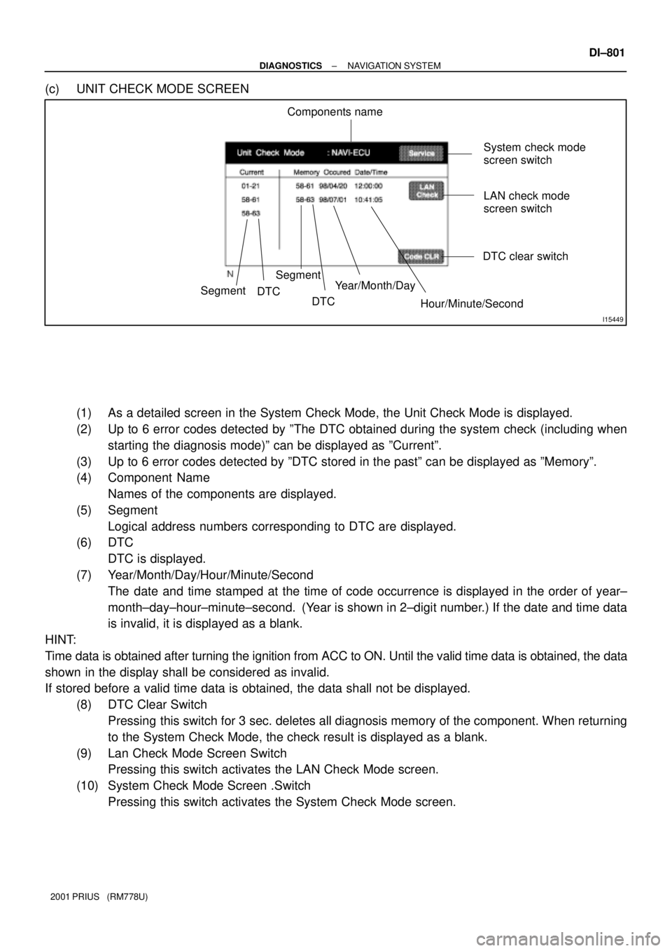
(1) As a detailed screen in the System Check Mode, the Unit Check Mode is displayed.
(2) Up to 6 error codes detected by ºThe DTC obtained during the system check (including when
starting the diagnosis mode)º can be displayed as ºCurrentº.
(3) Up to 6 error codes detected by ºDTC stored in the pastº can be displayed as ºMemoryº.
(4) Component Name
Names of the components are displayed.
(5) Segment
Logical address numbers corresponding to DTC are displayed.
(6) DTC
DTC is displayed.
(7) Year/Month/Day/Hour/Minute/Second
The date and time stamped at the time of code occurrence is displayed in the order of year±
month±day±hour±minute±second. (Year is shown in 2±digit number.) If the date and time data
is invalid, it is displayed as a blank.
HINT:
Time data is obtained after turning the ignition from ACC to ON. Until the valid time data is obtained, the data
shown in the display shall be considered as invalid.
If stored before a valid time data is obtained, the data shall not be displayed.
(8) DTC Clear Switch
Pressing this switch for 3 sec. deletes all diagnosis memory of the component. When returning
to the System Check Mode, the check result is displayed as a blank.
(9) Lan Check Mode Screen Switch
Pressing this switch activates the LAN Check Mode screen.
(10) System Check Mode Screen .Switch
Pressing this switch activates the System Check Mode screen.