Page 1462 of 1943
I18394
Engine Room J/B
CDS Fuse
RDI Fuse
± DIAGNOSTICSAIR CONDITIONING SYSTEM
DI±955
2001 PRIUS (RM778U)
3 Check RDI fuse and CDS fuse.
PREPARATION:
Remove RDI fuse and CDS fuse from engine room J/B.
CHECK:
Check continuity of RDI fuse and CDS fuse.
OK:
Continuity exists.
NG Check for short in all the harness and compo-
nents connected to the RDI fuse (See attached
wiring diagram).
OK
Check harness and connector between A/C control amplifier and battery (See page IN±41).
4 Check fan motor operation (See page AC±67).
NG Replace fan motor.
OK
5 Check pressure switch (See page AC±62).
NG Replace pressure switch.
OK
Page 1476 of 1943
EM1IU±03
A13907
A13908
A13934
A13943
± ENGINE MECHANICALTIMING CHAIN
EM±15
2001 PRIUS (RM778U)
REMOVAL
1. DISCONNECT BATTERY NEGATIVE (±) TERMINAL
AND HV BATTERY SERVICE PLUG
(See page HV±1)
2. REMOVE OUTER FR COWL TOP PANEL ASSEMBLY
(See page BO±32)
3. REMOVE RH ENGINE UNDER COVER
4. DRAIN ENGINE COOLANT
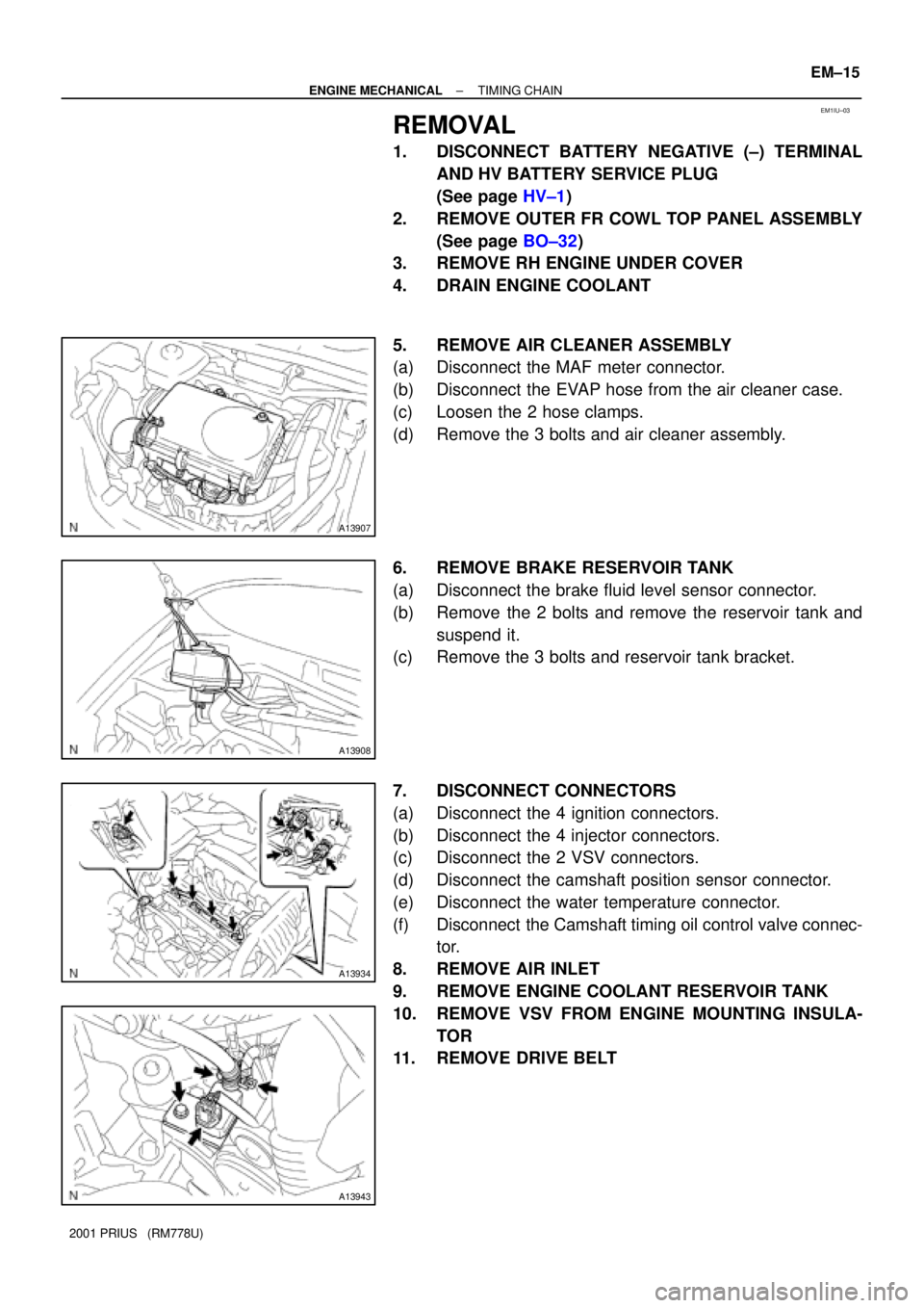
5. REMOVE AIR CLEANER ASSEMBLY
(a) Disconnect the MAF meter connector.
(b) Disconnect the EVAP hose from the air cleaner case.
(c) Loosen the 2 hose clamps.
(d) Remove the 3 bolts and air cleaner assembly.
6. REMOVE BRAKE RESERVOIR TANK
(a) Disconnect the brake fluid level sensor connector.
(b) Remove the 2 bolts and remove the reservoir tank and
suspend it.
(c) Remove the 3 bolts and reservoir tank bracket.
7. DISCONNECT CONNECTORS
(a) Disconnect the 4 ignition connectors.
(b) Disconnect the 4 injector connectors.
(c) Disconnect the 2 VSV connectors.
(d) Disconnect the camshaft position sensor connector.
(e) Disconnect the water temperature connector.
(f) Disconnect the Camshaft timing oil control valve connec-
tor.
8. REMOVE AIR INLET
9. REMOVE ENGINE COOLANT RESERVOIR TANK
10. REMOVE VSV FROM ENGINE MOUNTING INSULA-
TOR
11. REMOVE DRIVE BELT
Page 1484 of 1943
A13934
A13907
± ENGINE MECHANICALTIMING CHAIN
EM±25
2001 PRIUS (RM778U)
16. CONNECT CONNECTORS
(a) Connect the Camshaft timing oil control valve connector.
(b) Connect the water temperature sensor connector.
(c) Connect the camshaft position sensor connector.
(d) Connect the 2 VSV connectors.
(e) Connect the 4 injector connectors.
(f) Connect the 4 ignition connectors.
17. INSTALL AIR CLEANER ASSEMBLY
(a) Install the air cleaner assembly with the 2 bolts.
(b) Tighten the 2 hose clamps.
(c) Connect the EVAP hose to the air cleaner case.
(d) Connect the MAF meter connector.
18. INSTALL BRAKE RESERVOIR TANK
19. INSTALL OUTER FR COWL TOP PANEL ASSEMBLY
(See page BO±35)
20. FILL WITH ENGINE COOLANT
21. INSTALL ENGINE UNDER COVERS
22. CONNECT BATTERY NEGATIVE (±) TERMINAL AND
HV BATTERY SERVICE PLUG (See page HV±1)
23. ROAD TEST VEHICLE
Check for abnormal noises, shock slippage, correst shift points
and smooth operation.
24. RECHECK ENGINE COOLANT AND HV TRANSAXLE
COOLANT
Page 1488 of 1943
EM1IX±02
A13907
B11761
A13934
± ENGINE MECHANICALCYLINDER HEAD
EM±29
2001 PRIUS (RM778U)
REMOVAL
1. DISCONNECT BATTERY NEGATIVE (± )TERMINAL
AND HV BATTERY SERVICE PLUG
(See page HV±1)
2. REMOVE OUTER FRONT COWL TOP PANEL AS-
SEMBLY (See page BO±32)
3. DRAIN HV TRANSAXLE COOLANT
(See page HT±6)
4. DRAIN ENGINE COOLANT
5. REMOVE CONVERTER AND INVERTER ASSEMBLY
(See page HV±18)
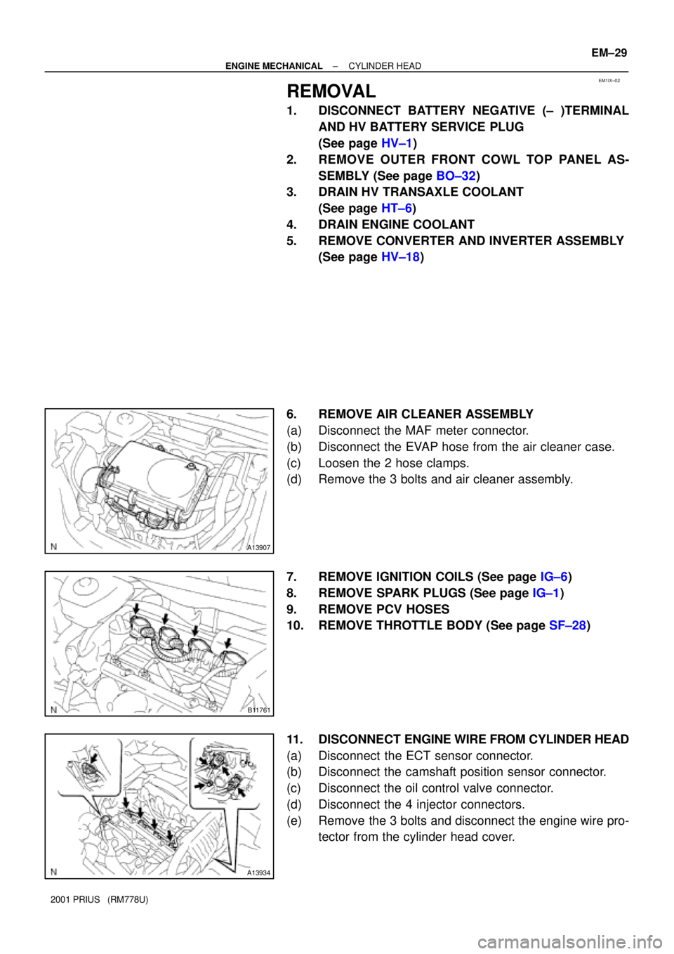
6. REMOVE AIR CLEANER ASSEMBLY
(a) Disconnect the MAF meter connector.
(b) Disconnect the EVAP hose from the air cleaner case.
(c) Loosen the 2 hose clamps.
(d) Remove the 3 bolts and air cleaner assembly.
7. REMOVE IGNITION COILS (See page IG±6)
8. REMOVE SPARK PLUGS (See page IG±1)
9. REMOVE PCV HOSES
10. REMOVE THROTTLE BODY (See page SF±28)
11. DISCONNECT ENGINE WIRE FROM CYLINDER HEAD
(a) Disconnect the ECT sensor connector.
(b) Disconnect the camshaft position sensor connector.
(c) Disconnect the oil control valve connector.
(d) Disconnect the 4 injector connectors.
(e) Remove the 3 bolts and disconnect the engine wire pro-
tector from the cylinder head cover.
Page 1506 of 1943
A13935
A13934
A13907
EM±48
± ENGINE MECHANICALCYLINDER HEAD
2001 PRIUS (RM778U)
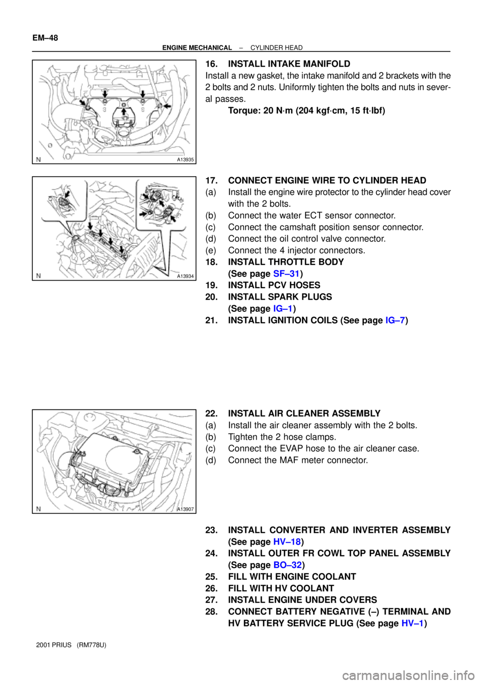
16. INSTALL INTAKE MANIFOLD
Install a new gasket, the intake manifold and 2 brackets with the
2 bolts and 2 nuts. Uniformly tighten the bolts and nuts in sever-
al passes.
Torque: 20 N´m (204 kgf´cm, 15 ft´lbf)
17. CONNECT ENGINE WIRE TO CYLINDER HEAD
(a) Install the engine wire protector to the cylinder head cover
with the 2 bolts.
(b) Connect the water ECT sensor connector.
(c) Connect the camshaft position sensor connector.
(d) Connect the oil control valve connector.
(e) Connect the 4 injector connectors.
18. INSTALL THROTTLE BODY
(See page SF±31)
19. INSTALL PCV HOSES
20. INSTALL SPARK PLUGS
(See page IG±1)
21. INSTALL IGNITION COILS (See page IG±7)
22. INSTALL AIR CLEANER ASSEMBLY
(a) Install the air cleaner assembly with the 2 bolts.
(b) Tighten the 2 hose clamps.
(c) Connect the EVAP hose to the air cleaner case.
(d) Connect the MAF meter connector.
23. INSTALL CONVERTER AND INVERTER ASSEMBLY
(See page HV±18)
24. INSTALL OUTER FR COWL TOP PANEL ASSEMBLY
(See page BO±32)
25. FILL WITH ENGINE COOLANT
26. FILL WITH HV COOLANT
27. INSTALL ENGINE UNDER COVERS
28. CONNECT BATTERY NEGATIVE (±) TERMINAL AND
HV BATTERY SERVICE PLUG (See page HV±1)
Page 1511 of 1943
EM1J0±02
A13907
A13943
± ENGINE MECHANICALENGINE UNIT
EM±53
2001 PRIUS (RM778U)
REMOVAL
1. DISCONNECT BATTERY NEGATIVE (±) TERMINAL
AND HV BATTERY SERVICE PLUG
(See page HV±1)
2. REMOVE OUTER FRONT COWL TOP PANEL AS-
SEMBLY (See page BO±32)
3. DRAIN HV COOLANT (See page HT±8)
4. DRAIN ENGINE COOLANT
5. REMOVE CONVERTER AND INVERTER ASSEMBLY
(See page HV±18)
6. REMOVE HEATER UNIT WATER PUMP
(See page AC±55)
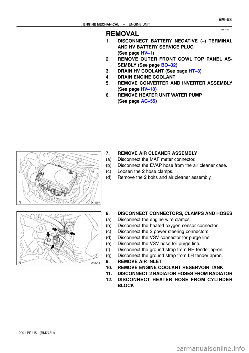
7. REMOVE AIR CLEANER ASSEMBLY
(a) Disconnect the MAF meter connector.
(b) Disconnect the EVAP hose from the air cleaner case.
(c) Loosen the 2 hose clamps.
(d) Remove the 2 bolts and air cleaner assembly.
8. DISCONNECT CONNECTORS, CLAMPS AND HOSES
(a) Disconnect the engine wire clamps.
(b) Disconnect the heated oxygen sensor connector.
(c) Disconnect the 2 power steering connectors.
(d) Disconnect the VSV connector for purge line.
(e) Disconnect the VSV hose for purge line.
(f) Disconnect the ground strap from RH fender apron.
(g) Disconnect the ground strap from LH fender apron.
9. REMOVE AIR INLET
10. REMOVE ENGINE COOLANT RESERVOIR TANK
11. DISCONNECT 2 RADIATOR HOSES FROM RADIATOR
12. DISCONNECT HEATER HOSE FROM CYLINDER
BLOCK
Page 1518 of 1943
A13943
A13907
± ENGINE MECHANICALENGINE UNIT
EM±61
2001 PRIUS (RM778U)
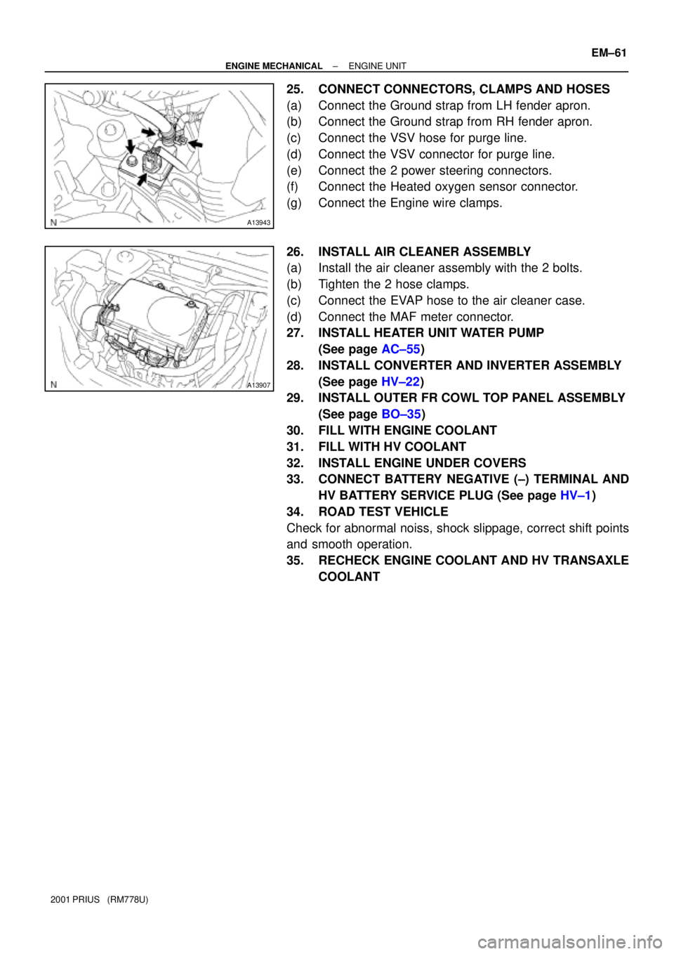
25. CONNECT CONNECTORS, CLAMPS AND HOSES
(a) Connect the Ground strap from LH fender apron.
(b) Connect the Ground strap from RH fender apron.
(c) Connect the VSV hose for purge line.
(d) Connect the VSV connector for purge line.
(e) Connect the 2 power steering connectors.
(f) Connect the Heated oxygen sensor connector.
(g) Connect the Engine wire clamps.
26. INSTALL AIR CLEANER ASSEMBLY
(a) Install the air cleaner assembly with the 2 bolts.
(b) Tighten the 2 hose clamps.
(c) Connect the EVAP hose to the air cleaner case.
(d) Connect the MAF meter connector.
27. INSTALL HEATER UNIT WATER PUMP
(See page AC±55)
28. INSTALL CONVERTER AND INVERTER ASSEMBLY
(See page HV±22)
29. INSTALL OUTER FR COWL TOP PANEL ASSEMBLY
(See page BO±35)
30. FILL WITH ENGINE COOLANT
31. FILL WITH HV COOLANT
32. INSTALL ENGINE UNDER COVERS
33. CONNECT BATTERY NEGATIVE (±) TERMINAL AND
HV BATTERY SERVICE PLUG (See page HV±1)
34. ROAD TEST VEHICLE
Check for abnormal noiss, shock slippage, correct shift points
and smooth operation.
35. RECHECK ENGINE COOLANT AND HV TRANSAXLE
COOLANT
Page 1542 of 1943
EC0HV±01
B04812
Gasket
B06544
Vacuum
Gauge
F12396
TOYOTA Hand±held Tester
B11799
± EMISSION CONTROLEVAPORATIVE EMISSION (EVAP) CONTROL SYSTEM
EC±7
2001 PRIUS (RM778U)
INSPECTION
1. REMOVE EXHAUST TAIL PIPE AND HEATED INSULA-
TOR (See page EM±84)
2. INSPECT LINES AND CONNECTORS
Visually check for loose connections, sharp bends or damage.
3. INSPECT FUEL TANK FILLER PIPE
Visually check for deformation, cracks or fuel leakage.
4. INSPECT FUEL TANK CAP
Visually check if the cap and/or gasket are deformed or dam-
aged.
If necessary, repair or replace the cap.
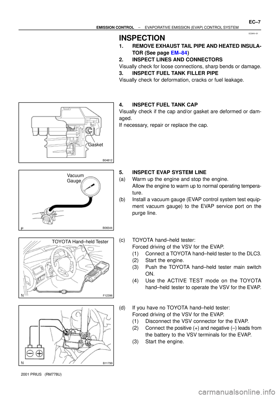
5. INSPECT EVAP SYSTEM LINE
(a) Warm up the engine and stop the engine.
Allow the engine to warm up to normal operating tempera-
ture.
(b) Install a vacuum gauge (EVAP control system test equip-
ment vacuum gauge) to the EVAP service port on the
purge line.
(c) TOYOTA hand±held tester:
Forced driving of the VSV for the EVAP.
(1) Connect a TOYOTA hand±held tester to the DLC3.
(2) Start the engine.
(3) Push the TOYOTA hand±held tester main switch
ON.
(4) Use the ACTIVE TEST mode on the TOYOTA
hand±held tester to operate the VSV for the EVAP.
(d) If you have no TOYOTA hand±held tester:
Forced driving of the VSV for the EVAP.
(1) Disconnect the VSV connector for the EVAP.
(2) Connect the positive (+) and negative (±) leads from
the battery to the VSV terminals for the EVAP.
(3) Start the engine.