Page 1564 of 1943

SF1KS±01
F12396
TOYOTA Hand±Held
Tester
DLC3
B11458
Ohmmeter1 (M±)
2 (M+)
SF±24
± SFITHROTTLE BODY
1238 Author�: Date�:
2001 PRIUS (RM778U)
THROTTLE BODY
ON±VEHICLE INSPECTION
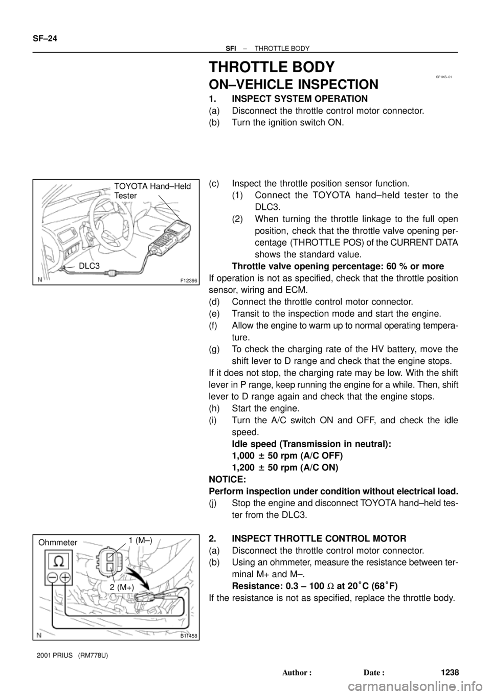
1. INSPECT SYSTEM OPERATION
(a) Disconnect the throttle control motor connector.
(b) Turn the ignition switch ON.
(c) Inspect the throttle position sensor function.
(1) Connect the TOYOTA hand±held tester to the
DLC3.
(2) When turning the throttle linkage to the full open
position, check that the throttle valve opening per-
centage (THROTTLE POS) of the CURRENT DATA
shows the standard value.
Throttle valve opening percentage: 60 % or more
If operation is not as specified, check that the throttle position
sensor, wiring and ECM.
(d) Connect the throttle control motor connector.
(e) Transit to the inspection mode and start the engine.
(f) Allow the engine to warm up to normal operating tempera-
ture.
(g) To check the charging rate of the HV battery, move the
shift lever to D range and check that the engine stops.
If it does not stop, the charging rate may be low. With the shift
lever in P range, keep running the engine for a while. Then, shift
lever to D range again and check that the engine stops.
(h) Start the engine.
(i) Turn the A/C switch ON and OFF, and check the idle
speed.
Idle speed (Transmission in neutral):
1,000 ± 50 rpm (A/C OFF)
1,200 ± 50 rpm (A/C ON)
NOTICE:
Perform inspection under condition without electrical load.
(j) Stop the engine and disconnect TOYOTA hand±held tes-
ter from the DLC3.
2. INSPECT THROTTLE CONTROL MOTOR
(a) Disconnect the throttle control motor connector.
(b) Using an ohmmeter, measure the resistance between ter-
minal M+ and M±.
Resistance: 0.3 ± 100 W at 20°C (68°F)
If the resistance is not as specified, replace the throttle body.
Page 1571 of 1943
B11749
Battery
Air A B
± SFIVSV FOR CANISTER CLOSED VALVE (CCV)
SF±43
2001 PRIUS (RM778U)
(b) Apply battery positive voltage across the terminals.
(c) Check that air does not flow from ports A to B.
If operation is not as specified, replace the VSV.
6. REINSTALL VSV
Page 1580 of 1943

I18027
No. 1 Cooling
Fan Relay
CO14D±01
B03548No ContinuityContinuity 12 Ohmmeter
5Ohmmeter
3
B03549
Ohmmeter
Continuity1
32
5
Battery
I18027
No. 2 Cooling
Fan Relay
B03550
Continuity
Ohmmeter
No Continuity Continuity4
1
32
Ohmmeter
5
Ohmmeter
± COOLINGCOOLING FAN RELAY
CO±27
1305 Author�: Date�:
2001 PRIUS (RM778U)
COOLING FAN RELAY
INSPECTION
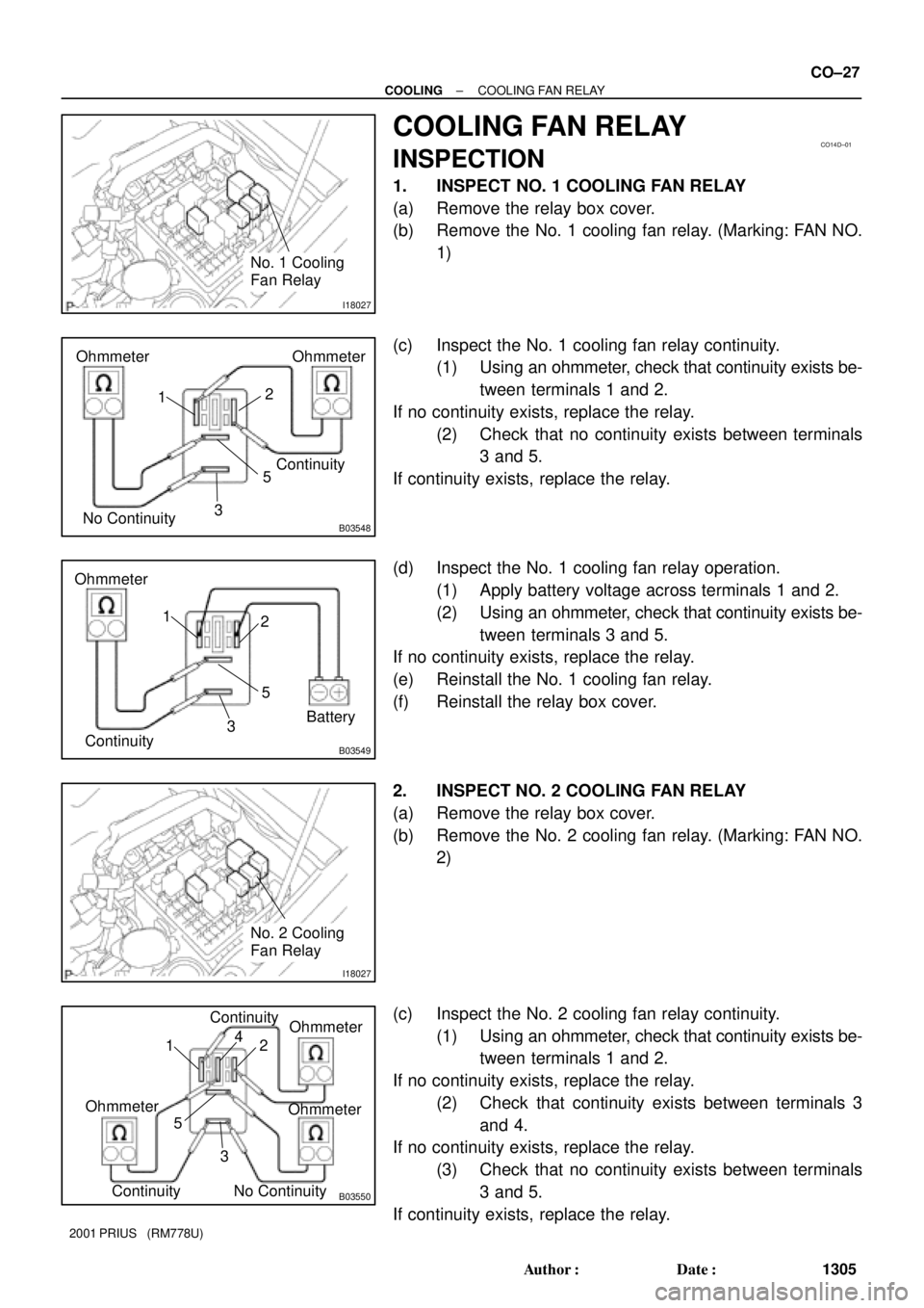
1. INSPECT NO. 1 COOLING FAN RELAY
(a) Remove the relay box cover.
(b) Remove the No. 1 cooling fan relay. (Marking: FAN NO.
1)
(c) Inspect the No. 1 cooling fan relay continuity.
(1) Using an ohmmeter, check that continuity exists be-
tween terminals 1 and 2.
If no continuity exists, replace the relay.
(2) Check that no continuity exists between terminals
3 and 5.
If continuity exists, replace the relay.
(d) Inspect the No. 1 cooling fan relay operation.
(1) Apply battery voltage across terminals 1 and 2.
(2) Using an ohmmeter, check that continuity exists be-
tween terminals 3 and 5.
If no continuity exists, replace the relay.
(e) Reinstall the No. 1 cooling fan relay.
(f) Reinstall the relay box cover.
2. INSPECT NO. 2 COOLING FAN RELAY
(a) Remove the relay box cover.
(b) Remove the No. 2 cooling fan relay. (Marking: FAN NO.
2)
(c) Inspect the No. 2 cooling fan relay continuity.
(1) Using an ohmmeter, check that continuity exists be-
tween terminals 1 and 2.
If no continuity exists, replace the relay.
(2) Check that continuity exists between terminals 3
and 4.
If no continuity exists, replace the relay.
(3) Check that no continuity exists between terminals
3 and 5.
If continuity exists, replace the relay.
Page 1581 of 1943

B03551
Ohmmeter
ContinuityOhmmeter
No Continuity4
1
32
5Battery
I18027
No. 3 Cooling
Fan Relay
B03548
Ohmmeter
No ContinuityOhmmeter
Continuity
5
3 12
B03549
Ohmmeter
Continuity5
3 12
Battery CO±28
± COOLINGCOOLING FAN RELAY
1306 Author�: Date�:
2001 PRIUS (RM778U)
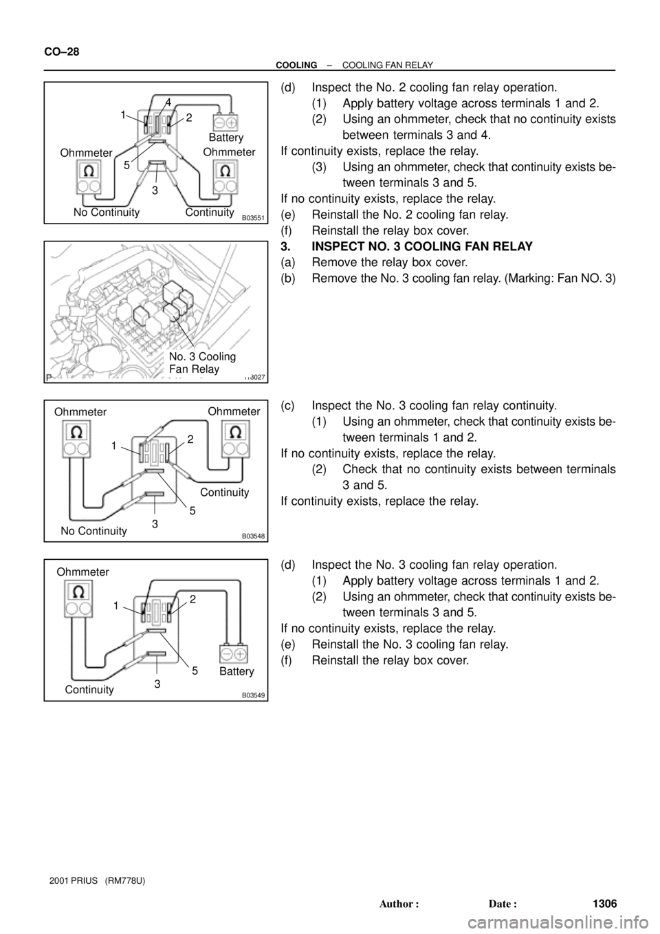
(d) Inspect the No. 2 cooling fan relay operation.
(1) Apply battery voltage across terminals 1 and 2.
(2) Using an ohmmeter, check that no continuity exists
between terminals 3 and 4.
If continuity exists, replace the relay.
(3) Using an ohmmeter, check that continuity exists be-
tween terminals 3 and 5.
If no continuity exists, replace the relay.
(e) Reinstall the No. 2 cooling fan relay.
(f) Reinstall the relay box cover.
3. INSPECT NO. 3 COOLING FAN RELAY
(a) Remove the relay box cover.
(b) Remove the No. 3 cooling fan relay. (Marking: Fan NO. 3)
(c) Inspect the No. 3 cooling fan relay continuity.
(1) Using an ohmmeter, check that continuity exists be-
tween terminals 1 and 2.
If no continuity exists, replace the relay.
(2) Check that no continuity exists between terminals
3 and 5.
If continuity exists, replace the relay.
(d) Inspect the No. 3 cooling fan relay operation.
(1) Apply battery voltage across terminals 1 and 2.
(2) Using an ohmmeter, check that continuity exists be-
tween terminals 3 and 5.
If no continuity exists, replace the relay.
(e) Reinstall the No. 3 cooling fan relay.
(f) Reinstall the relay box cover.
Page 1588 of 1943

CHECK POWER SUPPLY TO IGNITION COIL (WITH
SENSOR (See step 3)
SPARK TEST
Replace the crankshaft position sensor.
CHECK RESISTANCE OF CAMSHAFT POSITION
1. Turn ignition switch to ON.
2. Check that there is battery voltage at ignition coil positive (+)
terminal.
CHECK CONNECTION OF IGNITION COIL
CONNECTOR
Resistance:Cold Hot
CHECK RESISTANCE OF CRANKSHAFT POSITION
Resistance:Cold Hot 1,630 ± 2,740 W2,065 ± 3.225 W
CHECK IGT SIGNAL FROM ECM
(See page
DI±115)
TRY ANOTHER IGNITION COIL (WITH IGNITER)
Replace the camshaft position sensor. Connect securely.
Check wiring between ignition switch
to ignition coil (with igniter).
Check wiring between ECM and ignition
coil (with igniter), and then try another ECM.
NO
OK
OK
OK
OKBAD
BAD
BAD
BAD
BAD
SENSOR (See step 4) IGNITER) CHANGE IT TO NORMAL IGNITION COIL (WITH
IGNITER) AND PERFORM SPARK TEST AGAIN
OKReplace the ignition coil (with igniter).
NO
OK
985 ± 1,600 W1,265 ± 1,890 W
B11755
16 mm (0.63 in.)
Plug Wrench IG±2
± IGNITIONIGNITION SYSTEM
1319 Author�: Date�:
2001 PRIUS (RM778U)
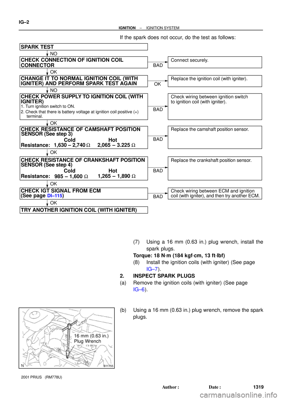
If the spark does not occur, do the test as follows:
(7) Using a 16 mm (0.63 in.) plug wrench, install the
spark plugs.
Torque: 18 N´m (184 kgf´cm, 13 ft´lbf)
(8) Install the ignition coils (with igniter) (See page
IG±7).
2. INSPECT SPARK PLUGS
(a) Remove the ignition coils (with igniter) (See page
IG±6).
(b) Using a 16 mm (0.63 in.) plug wrench, remove the spark
plugs.
Page 1591 of 1943
HV002±01
B11983N´m (kgf´cm, ft´lbf) : Specified torque
4.0 (41, 35 in.´lbf)
Inner Ventilator Duct
Lower Quarter
Ventilator
RH Battery
Bracket
HV Battery
Rear SeatQuarter Ventilator Duct
Blower Motor
Control Connector
LH Battery Bracket
Power Cable
Battery Carrier Catch Bracket
18 (185, 13)
x6
18 (185, 13)x5
x6
18 (185, 13)
8.0 (80, 71 in.´lbf)
4.0 (41, 35 in.´lbf)
5.0 (50, 44 in.´lbf)
18 (185, 13)
HV±2
± HYBRID VEHICLE CONTROLHV BATTERY
1332 Author�: Date�:
2001 PRIUS (RM778U)
HV BATTERY
COMPONENTS
Page 1592 of 1943
B11984N´m (kgf´cm, ft´lbf) : Specified torque
18 (185, 13)
Battery Cover
Busbar Module Protector
Busbar Module
Battery Hose
Service Plug
Assembly
Battery ECU
SMR Battery Clamp Bolt
RH Battery Bracket
HV Battery
Thermistor
Battery Carrier Battery Module
Busbar Module Protector
x38
x38
38 (390, 28)
Service Plug Wire Harness Protector
Busbar Module
38 (390, 28)
6.0 (61, 53 in.´lbf)
8.0 (80, 71 in.´lbf)
6.0 (61, 53 in.´lbf)
SMR Cover
5.0 (50, 44 in.´lbf)
5.0 (50, 44 in.´lbf)
3.3 (33, 29 in.´lbf)
5.0 (50, 44 in.´lbf)
5.0 (50, 44 in.´lbf)
± HYBRID VEHICLE CONTROLHV BATTERY
HV±3
1333 Author�: Date�:
2001 PRIUS (RM778U)
Page 1593 of 1943
HV004±01
B11963
B11964
B11965
± HYBRID VEHICLE CONTROLHV BATTERY
HV±5
2001 PRIUS (RM778U)
DISASSEMBLY
1. REMOVE BATTERY MODULE SET BOLT
Turn the battery assembly upside down, remove the 76 battery
module bolts.
NOTICE:
When turning it over, prevent the flange from being de-
formed.
HINT:
When not removing a battery module, skip the operation of step
1.
2. REMOVE BATTERY COVER
Remove the 12 bolts, screw and battery cover.
3. REMOVE SERVICE PLUG
(a) Remove the rear RH and LH busbar module protectors.
(b) Remove the 2 nuts for busbar module.
(c) Remove the nut and wire harness protector.