Page 1748 of 1943
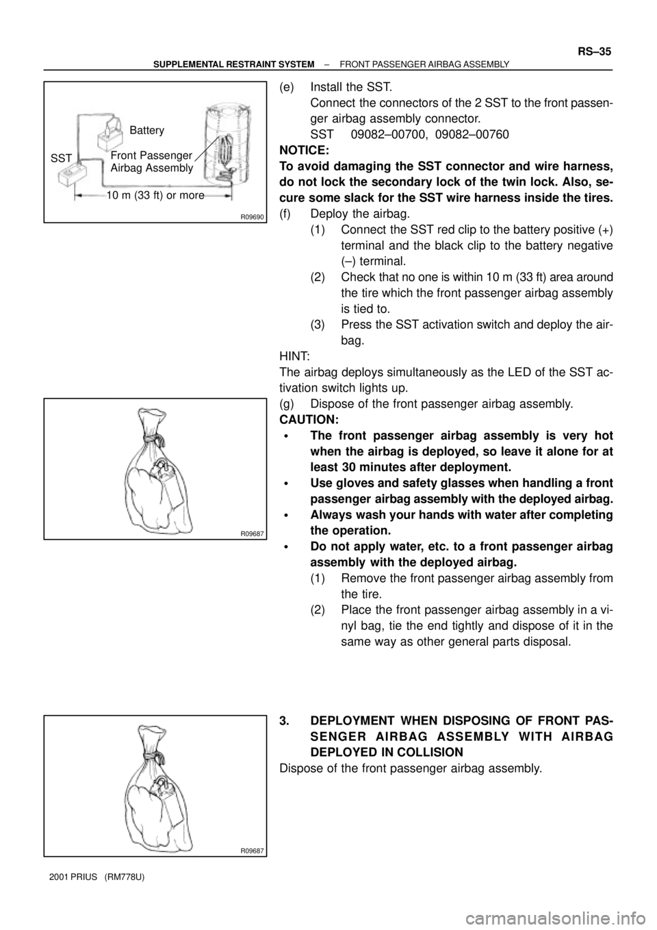
R09690
Battery
SSTFront Passenger
Airbag Assembly
10 m (33 ft) or more
R09687
R09687
± SUPPLEMENTAL RESTRAINT SYSTEMFRONT PASSENGER AIRBAG ASSEMBLY
RS±35
2001 PRIUS (RM778U)
(e) Install the SST.
Connect the connectors of the 2 SST to the front passen-
ger airbag assembly connector.
SST 09082±00700, 09082±00760
NOTICE:
To avoid damaging the SST connector and wire harness,
do not lock the secondary lock of the twin lock. Also, se-
cure some slack for the SST wire harness inside the tires.
(f) Deploy the airbag.
(1) Connect the SST red clip to the battery positive (+)
terminal and the black clip to the battery negative
(±) terminal.
(2) Check that no one is within 10 m (33 ft) area around
the tire which the front passenger airbag assembly
is tied to.
(3) Press the SST activation switch and deploy the air-
bag.
HINT:
The airbag deploys simultaneously as the LED of the SST ac-
tivation switch lights up.
(g) Dispose of the front passenger airbag assembly.
CAUTION:
�The front passenger airbag assembly is very hot
when the airbag is deployed, so leave it alone for at
least 30 minutes after deployment.
�Use gloves and safety glasses when handling a front
passenger airbag assembly with the deployed airbag.
�Always wash your hands with water after completing
the operation.
�Do not apply water, etc. to a front passenger airbag
assembly with the deployed airbag.
(1) Remove the front passenger airbag assembly from
the tire.
(2) Place the front passenger airbag assembly in a vi-
nyl bag, tie the end tightly and dispose of it in the
same way as other general parts disposal.
3. DEPLOYMENT WHEN DISPOSING OF FRONT PAS-
SENGER AIRBAG ASSEMBLY WITH AIRBAG
DEPLOYED IN COLLISION
Dispose of the front passenger airbag assembly.
Page 1750 of 1943

RS0RA±01
AB0152
SST
AB0158
Battery
SST RS±42
± SUPPLEMENTAL RESTRAINT SYSTEMSIDE AIRBAG ASSEMBLY
2001 PRIUS (RM778U)
DISPOSAL
HINT:
When scrapping vehicles equipped with an SRS or disposing
of the side airbag assembly always first deploy the airbag in ac-
cordance with the procedure described below. If any abnormal-
ity occurs with the airbag deployment, contact the SERVICE
DEPT. of TOYOTA MOTOR SALES, U.S.A., INC.
CAUTION:
�Never dispose of a side airbag assembly which has
an undeployed airbag.
�The airbag produces a sizeable exploding sound
when it deploys, so perform the operation out±of±
doors and where it will not create a nuisance to
nearby residents.
�When deploying the airbag, always use the specified
SST (SRS Airbag Deployment Tool), perform the op-
eration in a place away from electrical noise.
SST 09082±00700
�When deploying an airbag, perform the operation at
least 10 m (33 ft) away from the airbag assembly.
�The side airbag assembly is very hot when the airbag
is deployed, so leave it alone for at least 30 minutes
after deployment.
�Use gloves and safety glasses when handling side
airbag assembly with the deployed airbag.
�Always wash your hands with water after completing
the operation.
�Do not apply water, etc. to a side airbag assembly with
the deployed airbag.
1. AIRBAG DEPLOYMENT WHEN SCRAPPING VE-
HICLE
HINT:
Have a battery ready as the power source to deploy the airbag.
(a) Check functioning of the SST (See step 1±(a) on page
RS±16).
SST 09082±00700
Page 1751 of 1943
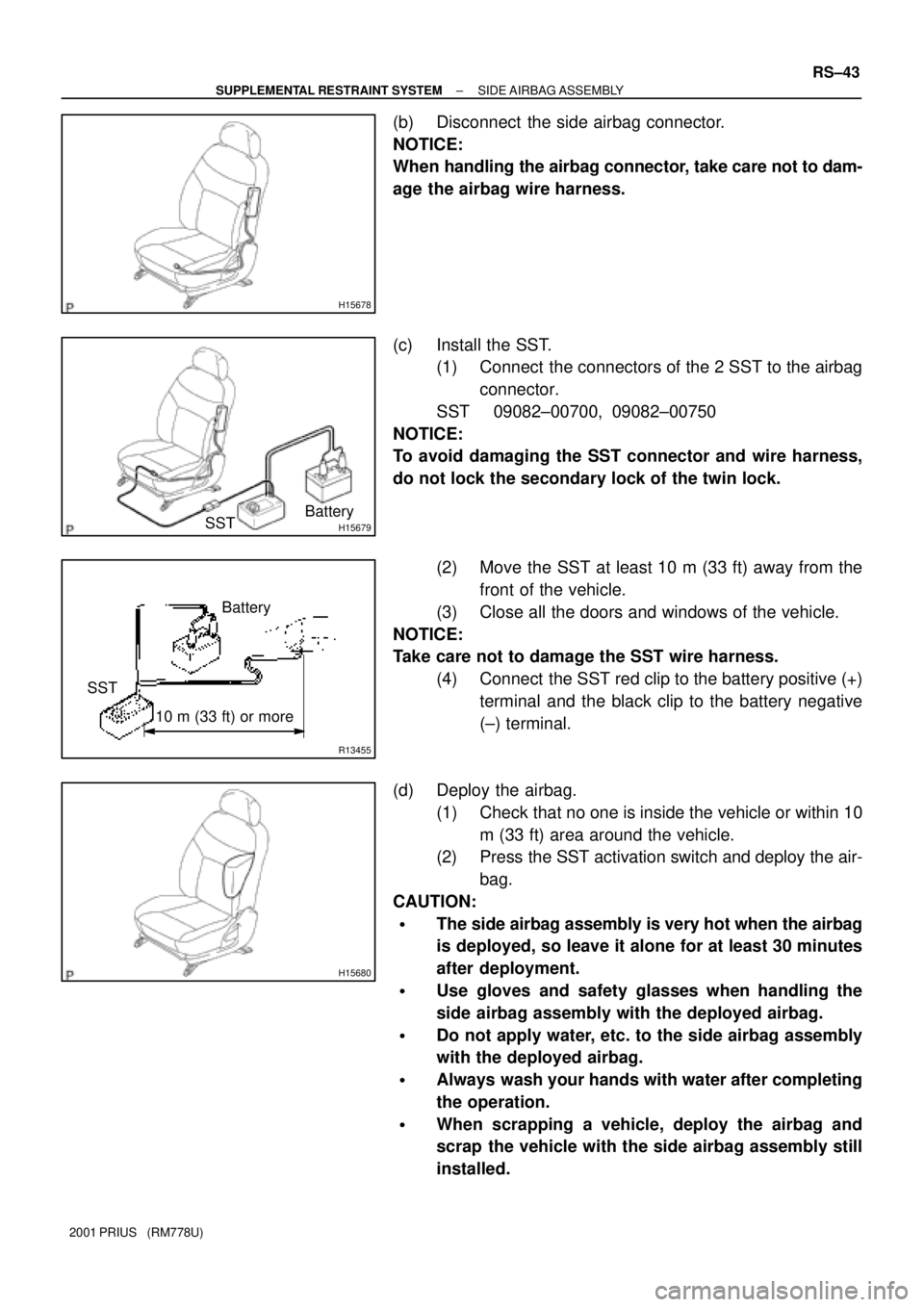
H15678
H15679Battery
SST
R13455
10 m (33 ft) or more
SSTBattery
H15680
± SUPPLEMENTAL RESTRAINT SYSTEMSIDE AIRBAG ASSEMBLY
RS±43
2001 PRIUS (RM778U)
(b) Disconnect the side airbag connector.
NOTICE:
When handling the airbag connector, take care not to dam-
age the airbag wire harness.
(c) Install the SST.
(1) Connect the connectors of the 2 SST to the airbag
connector.
SST 09082±00700, 09082±00750
NOTICE:
To avoid damaging the SST connector and wire harness,
do not lock the secondary lock of the twin lock.
(2) Move the SST at least 10 m (33 ft) away from the
front of the vehicle.
(3) Close all the doors and windows of the vehicle.
NOTICE:
Take care not to damage the SST wire harness.
(4) Connect the SST red clip to the battery positive (+)
terminal and the black clip to the battery negative
(±) terminal.
(d) Deploy the airbag.
(1) Check that no one is inside the vehicle or within 10
m (33 ft) area around the vehicle.
(2) Press the SST activation switch and deploy the air-
bag.
CAUTION:
�The side airbag assembly is very hot when the airbag
is deployed, so leave it alone for at least 30 minutes
after deployment.
�Use gloves and safety glasses when handling the
side airbag assembly with the deployed airbag.
�Do not apply water, etc. to the side airbag assembly
with the deployed airbag.
�Always wash your hands with water after completing
the operation.
�When scrapping a vehicle, deploy the airbag and
scrap the vehicle with the side airbag assembly still
installed.
Page 1752 of 1943
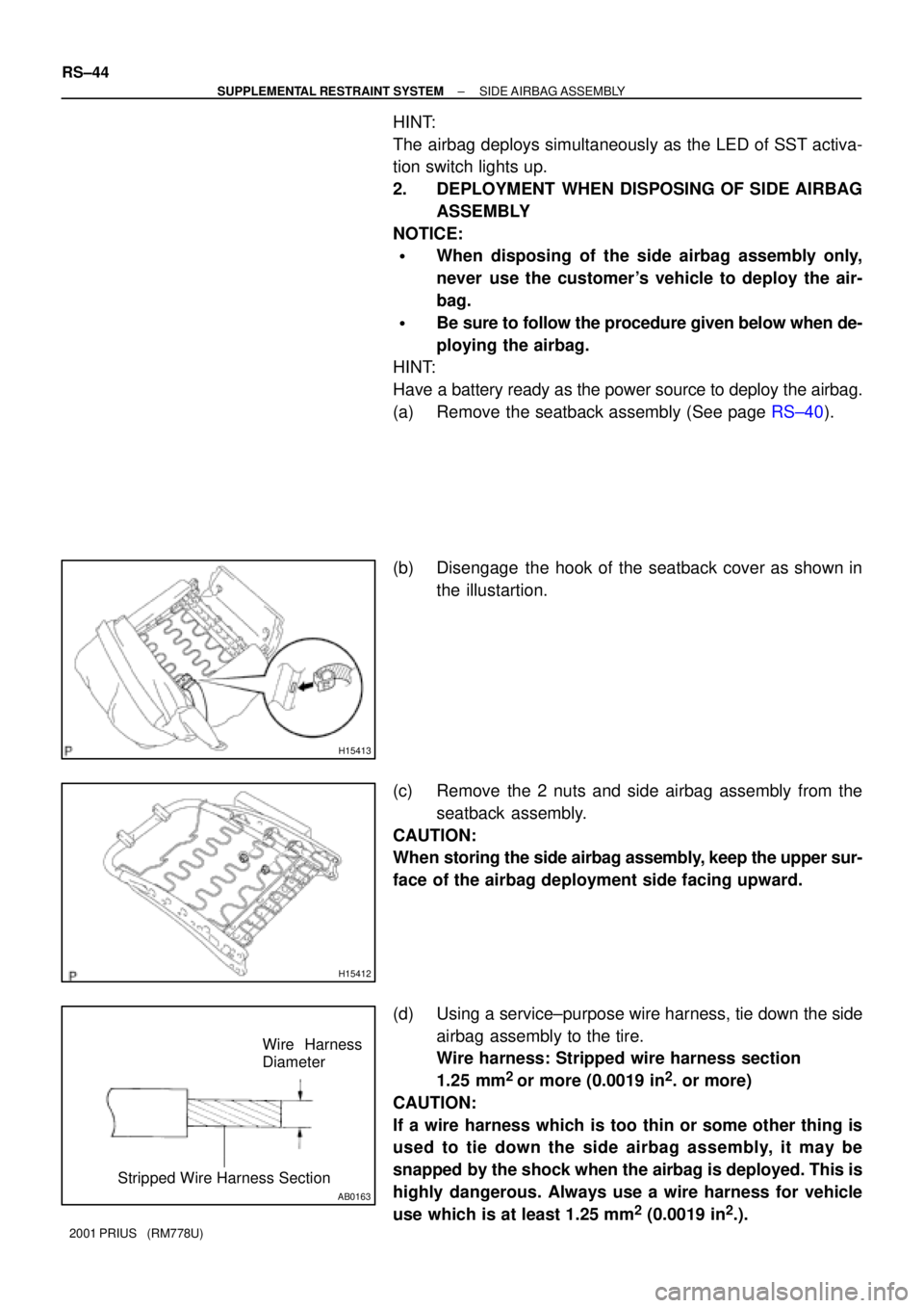
H15413
H15412
AB0163
Wire Harness
Diameter
Stripped Wire Harness Section
RS±44
± SUPPLEMENTAL RESTRAINT SYSTEMSIDE AIRBAG ASSEMBLY
2001 PRIUS (RM778U)
HINT:
The airbag deploys simultaneously as the LED of SST activa-
tion switch lights up.
2. DEPLOYMENT WHEN DISPOSING OF SIDE AIRBAG
ASSEMBLY
NOTICE:
�When disposing of the side airbag assembly only,
never use the customer's vehicle to deploy the air-
bag.
�Be sure to follow the procedure given below when de-
ploying the airbag.
HINT:
Have a battery ready as the power source to deploy the airbag.
(a) Remove the seatback assembly (See page RS±40).
(b) Disengage the hook of the seatback cover as shown in
the illustartion.
(c) Remove the 2 nuts and side airbag assembly from the
seatback assembly.
CAUTION:
When storing the side airbag assembly, keep the upper sur-
face of the airbag deployment side facing upward.
(d) Using a service±purpose wire harness, tie down the side
airbag assembly to the tire.
Wire harness: Stripped wire harness section
1.25 mm
2
or more (0.0019 in2. or more)
CAUTION:
If a wire harness which is too thin or some other thing is
used to tie down the side airbag assembly, it may be
snapped by the shock when the airbag is deployed. This is
highly dangerous. Always use a wire harness for vehicle
use which is at least 1.25 mm
2 (0.0019 in2.).
Page 1754 of 1943
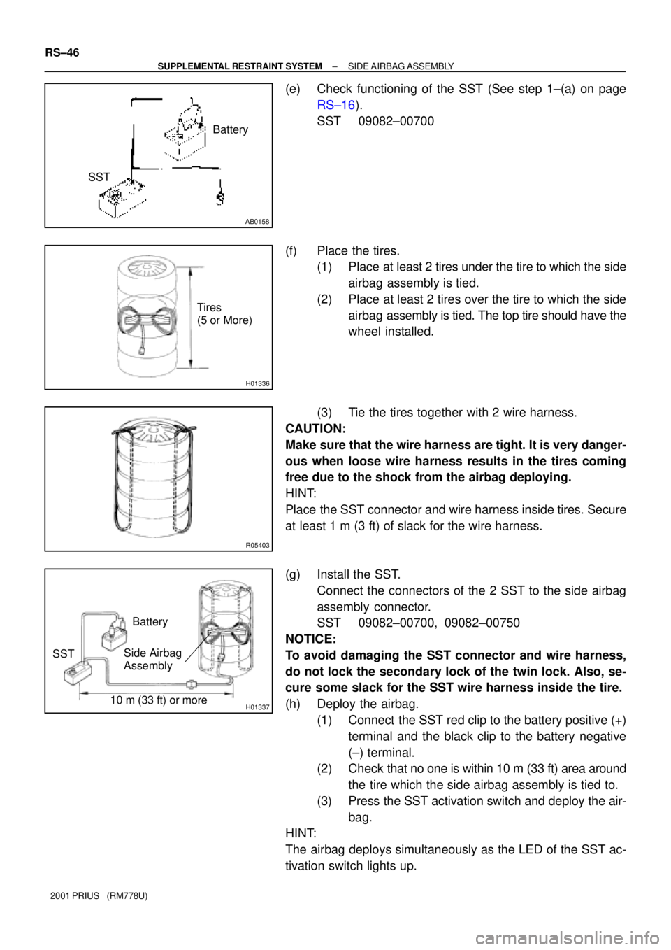
AB0158
SSTBattery
H01336
Tires
(5 or More)
R05403
H0133710 m (33 ft) or more SSTBattery
Side Airbag
Assembly
RS±46
± SUPPLEMENTAL RESTRAINT SYSTEMSIDE AIRBAG ASSEMBLY
2001 PRIUS (RM778U)
(e) Check functioning of the SST (See step 1±(a) on page
RS±16).
SST 09082±00700
(f) Place the tires.
(1) Place at least 2 tires under the tire to which the side
airbag assembly is tied.
(2) Place at least 2 tires over the tire to which the side
airbag assembly is tied. The top tire should have the
wheel installed.
(3) Tie the tires together with 2 wire harness.
CAUTION:
Make sure that the wire harness are tight. It is very danger-
ous when loose wire harness results in the tires coming
free due to the shock from the airbag deploying.
HINT:
Place the SST connector and wire harness inside tires. Secure
at least 1 m (3 ft) of slack for the wire harness.
(g) Install the SST.
Connect the connectors of the 2 SST to the side airbag
assembly connector.
SST 09082±00700, 09082±00750
NOTICE:
To avoid damaging the SST connector and wire harness,
do not lock the secondary lock of the twin lock. Also, se-
cure some slack for the SST wire harness inside the tire.
(h) Deploy the airbag.
(1) Connect the SST red clip to the battery positive (+)
terminal and the black clip to the battery negative
(±) terminal.
(2) Check that no one is within 10 m (33 ft) area around
the tire which the side airbag assembly is tied to.
(3) Press the SST activation switch and deploy the air-
bag.
HINT:
The airbag deploys simultaneously as the LED of the SST ac-
tivation switch lights up.
Page 1774 of 1943
I17862
Wire Harness Side
h±10±1±A
± BODY ELECTRICALHEADLIGHT AND TAILLIGHT SYSTEM
BE±21
2001 PRIUS (RM778U)
6. INSPECT DAYTIME RUNNING LIGHT MAIN RELAY
CIRCUIT
Disconnect the connector from the relay and inspect the con-
nector on the wire harness side.
Tester connectionConditionSpecified condition
2 ± GroundConstantContinuity
3 ± GroundConstantBattery voltage
4 ± GroundTerminal 5 groundBattery voltage
6 ± GroundConstantBattery voltage
7 ± GroundLight control switch OFF or TAILNo continuity
7 ± GroundLight control switch HEADContinuity
8 ± GroundHeadlight dimmer switch FLASH or HIContinuity
9 ± GroundEngine runningBattery voltage
12 ± GroundIgnition switch OFFNo voltage
12 ± GroundIgnition switch ONBattery voltage
If circuit is specified, try replacing the relay with a new one.
If circuit is not as specified, inspect the circuits connected to oth-
er parts.
Page 1779 of 1943
I14298
2 87
11
17
16
MISTLO
OFF HI
INT
Washer ON
BE1V1±01
I01313
2 7
16
I01314
2 7
16 17
INT time control
switch positionVoltage
Approx. 1 ~ 3 sec.
Battery voltage
0 Volt
Battery voltage
0 Volt Approx. 10 ~ 15 secs. FAST
SLOW
BE±34
± BODY ELECTRICALWIPER AND WASHER SYSTEM
2001 PRIUS (RM778U)
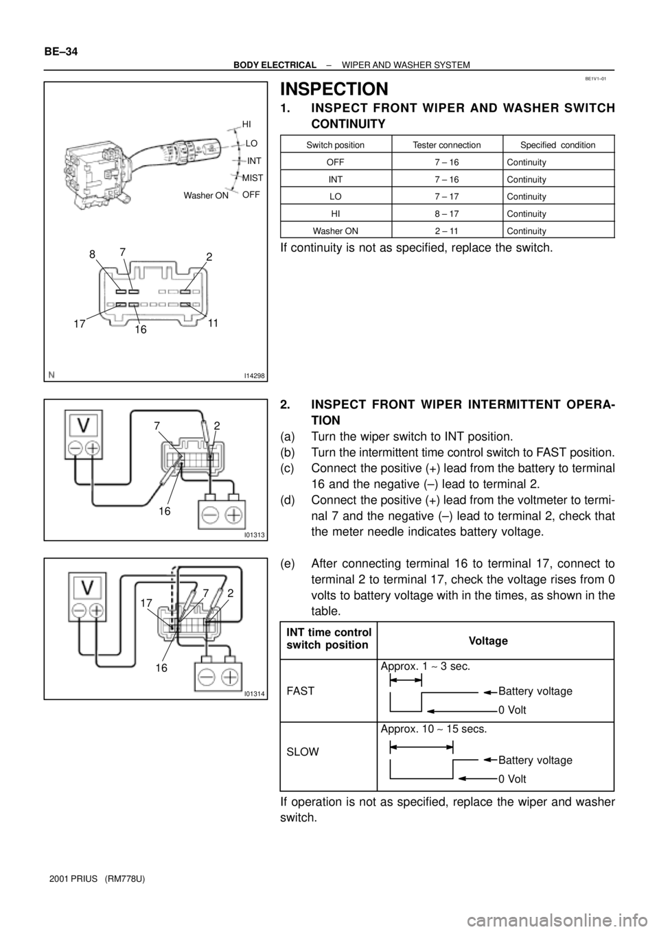
INSPECTION
1. INSPECT FRONT WIPER AND WASHER SWITCH
CONTINUITY
Switch positionTester connectionSpecified condition
OFF7 ± 16Continuity
INT7 ± 16Continuity
LO7 ± 17Continuity
HI8 ± 17Continuity
Washer ON2 ± 11Continuity
If continuity is not as specified, replace the switch.
2. INSPECT FRONT WIPER INTERMITTENT OPERA-
TION
(a) Turn the wiper switch to INT position.
(b) Turn the intermittent time control switch to FAST position.
(c) Connect the positive (+) lead from the battery to terminal
16 and the negative (±) lead to terminal 2.
(d) Connect the positive (+) lead from the voltmeter to termi-
nal 7 and the negative (±) lead to terminal 2, check that
the meter needle indicates battery voltage.
(e) After connecting terminal 16 to terminal 17, connect to
terminal 2 to terminal 17, check the voltage rises from 0
volts to battery voltage with in the times, as shown in the
table.
If operation is not as specified, replace the wiper and washer
switch.
Page 1780 of 1943
I01313
2 7
16
Washer Switch ON
Battery voltageLess than 1 sec. Approx. 3 secs. OFF
0 Volt
I11672
54
I11673
4 3
I11674
5
4
± BODY ELECTRICALWIPER AND WASHER SYSTEM
BE±35
2001 PRIUS (RM778U)
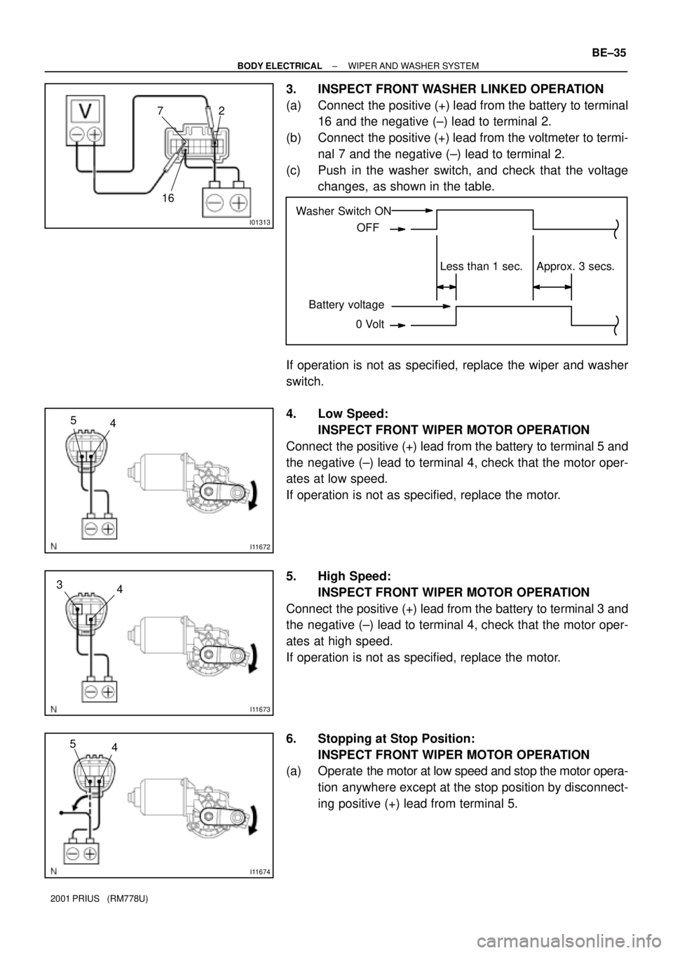
3. INSPECT FRONT WASHER LINKED OPERATION
(a) Connect the positive (+) lead from the battery to terminal
16 and the negative (±) lead to terminal 2.
(b) Connect the positive (+) lead from the voltmeter to termi-
nal 7 and the negative (±) lead to terminal 2.
(c) Push in the washer switch, and check that the voltage
changes, as shown in the table.
If operation is not as specified, replace the wiper and washer
switch.
4. Low Speed:
INSPECT FRONT WIPER MOTOR OPERATION
Connect the positive (+) lead from the battery to terminal 5 and
the negative (±) lead to terminal 4, check that the motor oper-
ates at low speed.
If operation is not as specified, replace the motor.
5. High Speed:
INSPECT FRONT WIPER MOTOR OPERATION
Connect the positive (+) lead from the battery to terminal 3 and
the negative (±) lead to terminal 4, check that the motor oper-
ates at high speed.
If operation is not as specified, replace the motor.
6. Stopping at Stop Position:
INSPECT FRONT WIPER MOTOR OPERATION
(a) Operate the motor at low speed and stop the motor opera-
tion anywhere except at the stop position by disconnect-
ing positive (+) lead from terminal 5.