Page 1781 of 1943
I11675
1
54 2
BE±36
± BODY ELECTRICALWIPER AND WASHER SYSTEM
2001 PRIUS (RM778U)
(b) Connect terminals 1 and 5.
(c) Connect the positive (+) lead from the battery to terminal
2 and negative (±) lead to terminal 4, check that the motor
stops running at the stop position after the motor operates
again.
If operation is not as specified, replace the motor.
Page 1789 of 1943
I17865
Fuel Sender Gauge Connector
I17865
Fuel Sender Gauge Connector
I01277
BatteryWarning Light Ignition
Switch
Wire Harness Side
1
I01278
BE±44
± BODY ELECTRICALCOMBINATION METER
2001 PRIUS (RM778U)
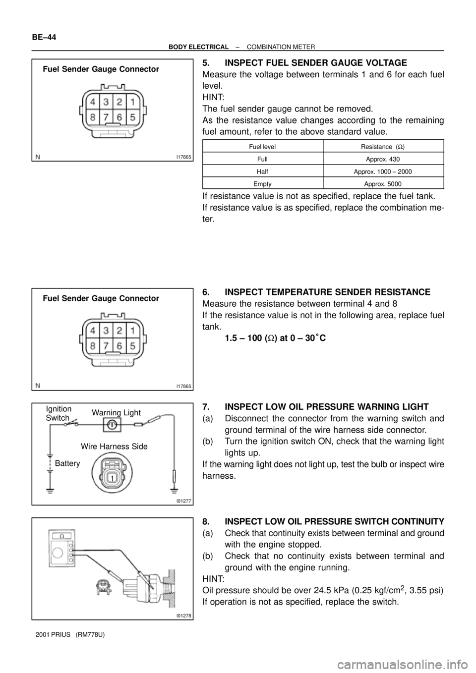
5. INSPECT FUEL SENDER GAUGE VOLTAGE
Measure the voltage between terminals 1 and 6 for each fuel
level.
HINT:
The fuel sender gauge cannot be removed.
As the resistance value changes according to the remaining
fuel amount, refer to the above standard value.
Fuel levelResistance (W)
FullApprox. 430
HalfApprox. 1000 ± 2000
EmptyApprox. 5000
If resistance value is not as specified, replace the fuel tank.
If resistance value is as specified, replace the combination me-
ter.
6. INSPECT TEMPERATURE SENDER RESISTANCE
Measure the resistance between terminal 4 and 8
If the resistance value is not in the following area, replace fuel
tank.
1.5 ± 100 (W) at 0 ± 30°C
7. INSPECT LOW OIL PRESSURE WARNING LIGHT
(a) Disconnect the connector from the warning switch and
ground terminal of the wire harness side connector.
(b) Turn the ignition switch ON, check that the warning light
lights up.
If the warning light does not light up, test the bulb or inspect wire
harness.
8. INSPECT LOW OIL PRESSURE SWITCH CONTINUITY
(a) Check that continuity exists between terminal and ground
with the engine stopped.
(b) Check that no continuity exists between terminal and
ground with the engine running.
HINT:
Oil pressure should be over 24.5 kPa (0.25 kgf/cm
2, 3.55 psi)
If operation is not as specified, replace the switch.
Page 1790 of 1943
BE1217
BatteryWarning Light
Ignition
Switch
I11650
BE0044
BatteryWarning Light
Ignition
Switch
Z11183
± BODY ELECTRICALCOMBINATION METER
BE±45
2001 PRIUS (RM778U)
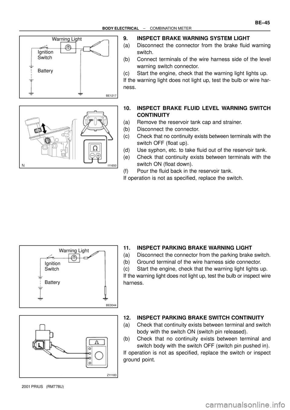
9. INSPECT BRAKE WARNING SYSTEM LIGHT
(a) Disconnect the connector from the brake fluid warning
switch.
(b) Connect terminals of the wire harness side of the level
warning switch connector.
(c) Start the engine, check that the warning light lights up.
If the warning light does not light up, test the bulb or wire har-
ness.
10. INSPECT BRAKE FLUID LEVEL WARNING SWITCH
CONTINUITY
(a) Remove the reservoir tank cap and strainer.
(b) Disconnect the connector.
(c) Check that no continuity exists between terminals with the
switch OFF (float up).
(d) Use syphon, etc. to take fluid out of the reservoir tank.
(e) Check that continuity exists between terminals with the
switch ON (float down).
(f) Pour the fluid back in the reservoir tank.
If operation is not as specified, replace the switch.
11. INSPECT PARKING BRAKE WARNING LIGHT
(a) Disconnect the connector from the parking brake switch.
(b) Ground terminal of the wire harness side connector.
(c) Start the engine, check that the warning light lights up.
If the warning light does not light up, test the bulb or inspect wire
harness.
12. INSPECT PARKING BRAKE SWITCH CONTINUITY
(a) Check that continuity exists between terminal and switch
body with the switch ON (switch pin released).
(b) Check that no continuity exists between terminal and
switch body with the switch OFF (switch pin pushed in).
If operation is not as specified, replace the switch or inspect
ground point.
Page 1791 of 1943
BE0044
BatteryWarning Light
Ignition
Switch BE±46
± BODY ELECTRICALCOMBINATION METER
2001 PRIUS (RM778U)
13. INSPECT OPEN DOOR WARNING LIGHT
Disconnect the connector from the door courtesy switch, and
ground terminal 1 of the wire harness side connector and check
that the warning light lights up.
If the warning light does not light up, inspect the bulb or wire har-
ness.
Page 1792 of 1943
BE1D5±03
I17792
8 71
I17793
I01200
2 1
35
2 5
1 3
± BODY ELECTRICALDEFOGGER SYSTEM
BE±49
2001 PRIUS (RM778U)
INSPECTION
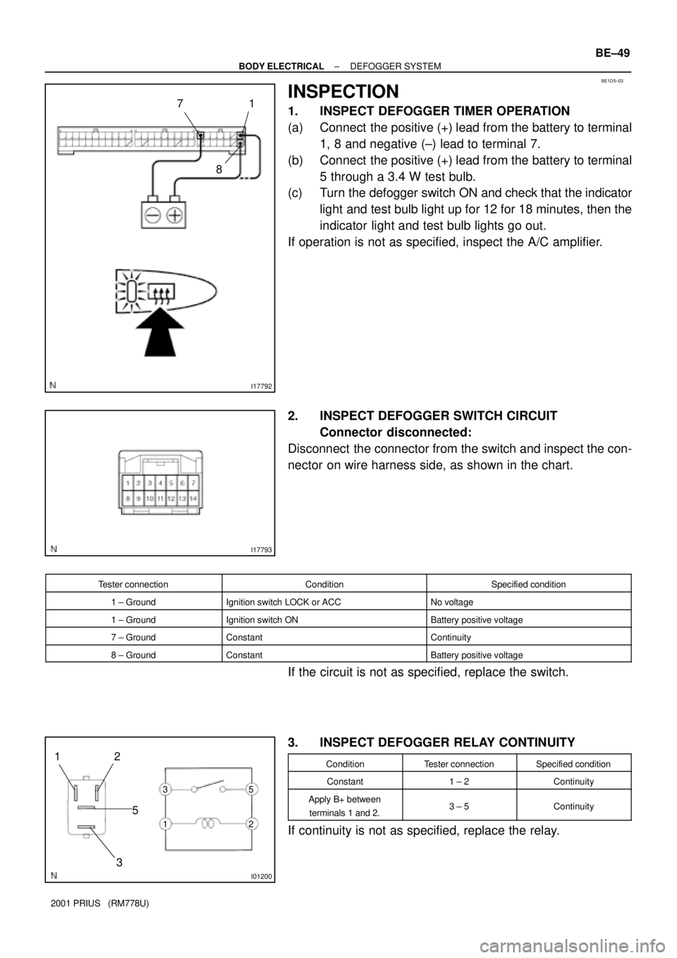
1. INSPECT DEFOGGER TIMER OPERATION
(a) Connect the positive (+) lead from the battery to terminal
1, 8 and negative (±) lead to terminal 7.
(b) Connect the positive (+) lead from the battery to terminal
5 through a 3.4 W test bulb.
(c) Turn the defogger switch ON and check that the indicator
light and test bulb light up for 12 for 18 minutes, then the
indicator light and test bulb lights go out.
If operation is not as specified, inspect the A/C amplifier.
2. INSPECT DEFOGGER SWITCH CIRCUIT
Connector disconnected:
Disconnect the connector from the switch and inspect the con-
nector on wire harness side, as shown in the chart.
Tester connectionConditionSpecified condition
1 ± GroundIgnition switch LOCK or ACCNo voltage
1 ± GroundIgnition switch ONBattery positive voltage
7 ± GroundConstantContinuity
8 ± GroundConstantBattery positive voltage
If the circuit is not as specified, replace the switch.
3. INSPECT DEFOGGER RELAY CONTINUITY
ConditionTester connectionSpecified condition
Constant1 ± 2Continuity
Apply B+ between
terminals 1 and 2.3 ± 5Continuity
If continuity is not as specified, replace the relay.
Page 1798 of 1943
I17796
21
BE1V3±02
I17797
5
I08152
BE±56
± BODY ELECTRICALPOWER WINDOW CONTROL SYSTEM
2001 PRIUS (RM778U)
INSPECTION
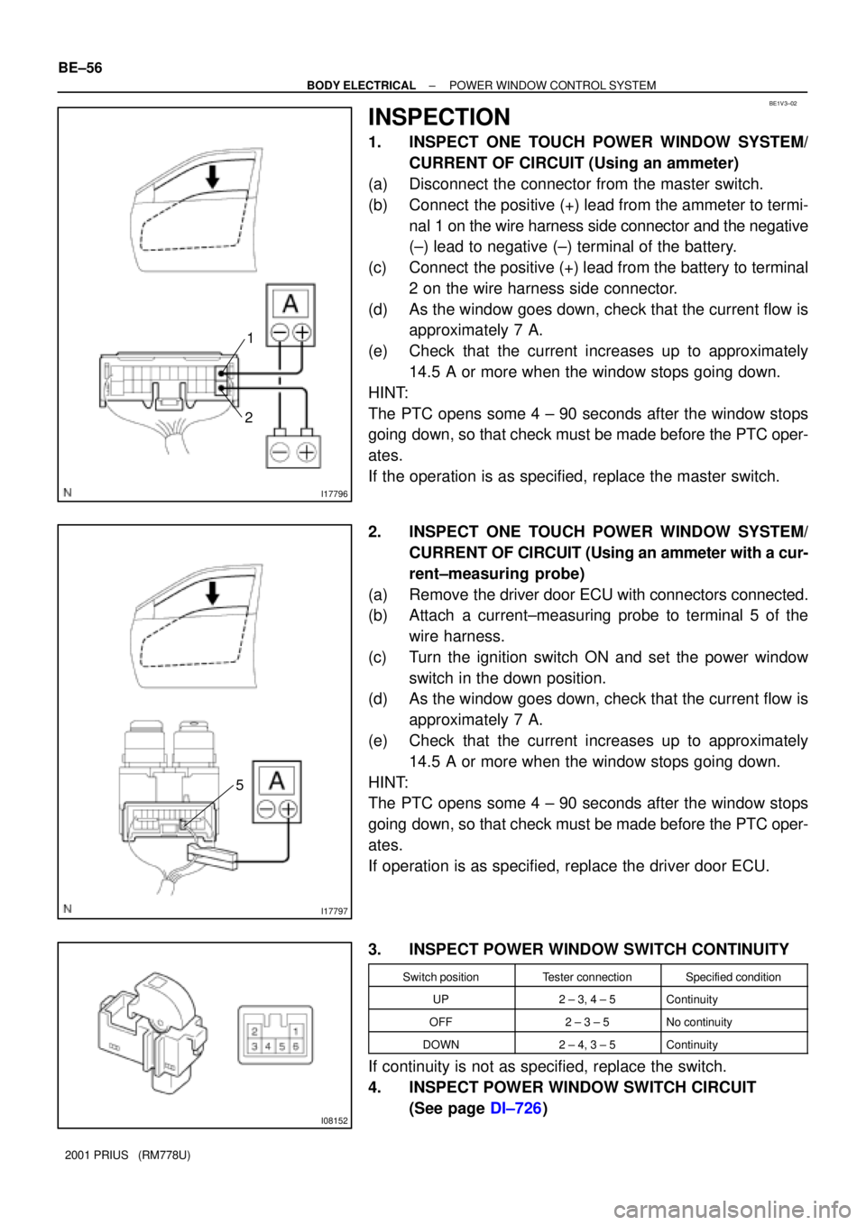
1. INSPECT ONE TOUCH POWER WINDOW SYSTEM/
CURRENT OF CIRCUIT (Using an ammeter)
(a) Disconnect the connector from the master switch.
(b) Connect the positive (+) lead from the ammeter to termi-
nal 1 on the wire harness side connector and the negative
(±) lead to negative (±) terminal of the battery.
(c) Connect the positive (+) lead from the battery to terminal
2 on the wire harness side connector.
(d) As the window goes down, check that the current flow is
approximately 7 A.
(e) Check that the current increases up to approximately
14.5 A or more when the window stops going down.
HINT:
The PTC opens some 4 ± 90 seconds after the window stops
going down, so that check must be made before the PTC oper-
ates.
If the operation is as specified, replace the master switch.
2. INSPECT ONE TOUCH POWER WINDOW SYSTEM/
CURRENT OF CIRCUIT (Using an ammeter with a cur-
rent±measuring probe)
(a) Remove the driver door ECU with connectors connected.
(b) Attach a current±measuring probe to terminal 5 of the
wire harness.
(c) Turn the ignition switch ON and set the power window
switch in the down position.
(d) As the window goes down, check that the current flow is
approximately 7 A.
(e) Check that the current increases up to approximately
14.5 A or more when the window stops going down.
HINT:
The PTC opens some 4 ± 90 seconds after the window stops
going down, so that check must be made before the PTC oper-
ates.
If operation is as specified, replace the driver door ECU.
3. INSPECT POWER WINDOW SWITCH CONTINUITY
Switch positionTester connectionSpecified condition
UP2 ± 3, 4 ± 5Continuity
OFF2 ± 3 ± 5No continuity
DOWN2 ± 4, 3 ± 5Continuity
If continuity is not as specified, replace the switch.
4. INSPECT POWER WINDOW SWITCH CIRCUIT
(See page DI±726)
Page 1799 of 1943
Z05930
1
2
3
5 1
5
2 3
I1535121
I1535221
I15353
2
1
I153542
1
± BODY ELECTRICALPOWER WINDOW CONTROL SYSTEM
BE±57
2001 PRIUS (RM778U)
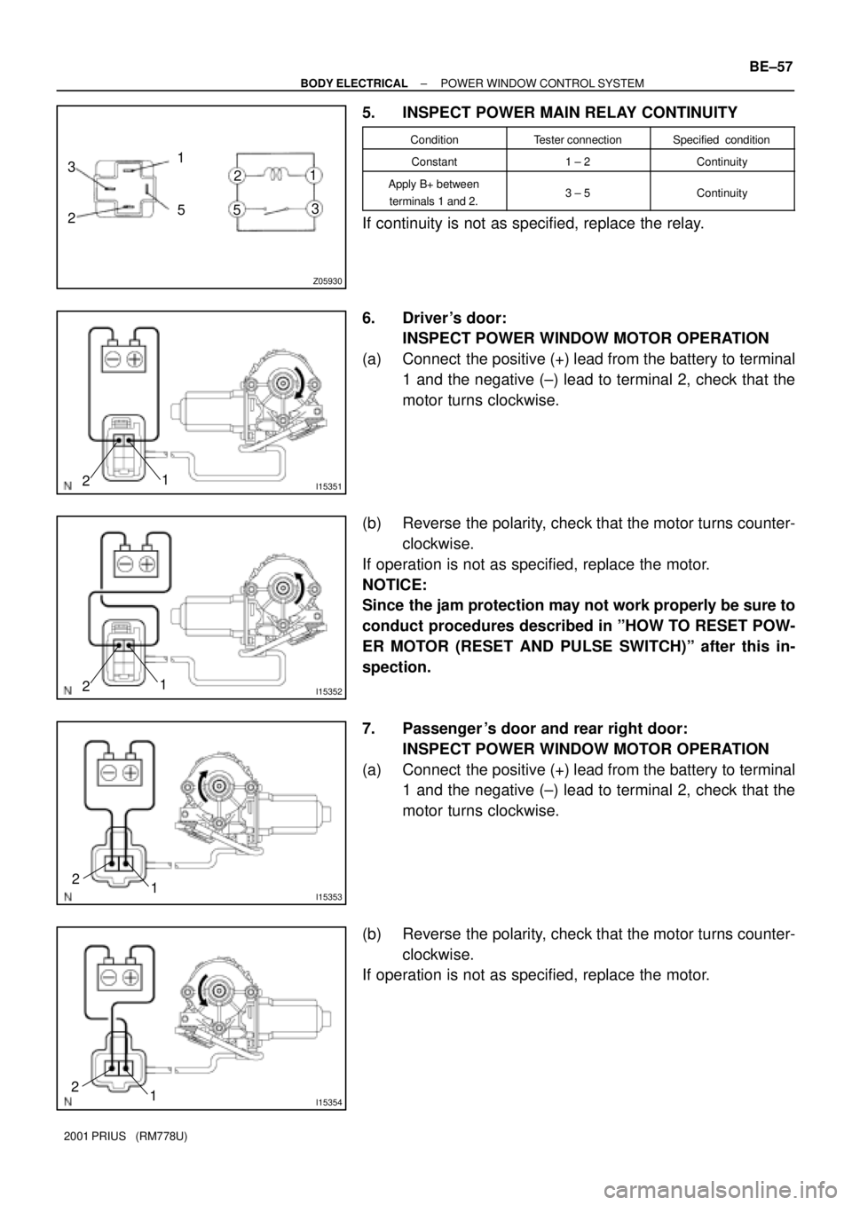
5. INSPECT POWER MAIN RELAY CONTINUITY
ConditionTester connectionSpecified condition
Constant1 ± 2Continuity
Apply B+ between
terminals 1 and 2.3 ± 5Continuity
If continuity is not as specified, replace the relay.
6. Driver 's door:
INSPECT POWER WINDOW MOTOR OPERATION
(a) Connect the positive (+) lead from the battery to terminal
1 and the negative (±) lead to terminal 2, check that the
motor turns clockwise.
(b) Reverse the polarity, check that the motor turns counter-
clockwise.
If operation is not as specified, replace the motor.
NOTICE:
Since the jam protection may not work properly be sure to
conduct procedures described in ºHOW TO RESET POW-
ER MOTOR (RESET AND PULSE SWITCH)º after this in-
spection.
7. Passenger 's door and rear right door:
INSPECT POWER WINDOW MOTOR OPERATION
(a) Connect the positive (+) lead from the battery to terminal
1 and the negative (±) lead to terminal 2, check that the
motor turns clockwise.
(b) Reverse the polarity, check that the motor turns counter-
clockwise.
If operation is not as specified, replace the motor.
Page 1800 of 1943
I15357
2
1
I15358
2
1
I14317
21
I1431821
I14319
21
BE±58
± BODY ELECTRICALPOWER WINDOW CONTROL SYSTEM
2001 PRIUS (RM778U)
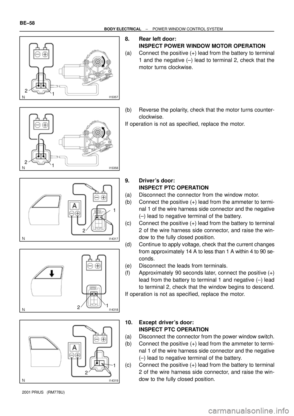
8. Rear left door:
INSPECT POWER WINDOW MOTOR OPERATION
(a) Connect the positive (+) lead from the battery to terminal
1 and the negative (±) lead to terminal 2, check that the
motor turns clockwise.
(b) Reverse the polarity, check that the motor turns counter-
clockwise.
If operation is not as specified, replace the motor.
9. Driver 's door:
INSPECT PTC OPERATION
(a) Disconnect the connector from the window motor.
(b) Connect the positive (+) lead from the ammeter to termi-
nal 1 of the wire harness side connector and the negative
(±) lead to negative terminal of the battery.
(c) Connect the positive (+) lead from the battery to terminal
2 of the wire harness side connector, and raise the win-
dow to the fully closed position.
(d) Continue to apply voltage, check that the current changes
from approximately 14 A to less than 1 A within 4 to 90 se-
conds.
(e) Disconnect the leads from terminals.
(f) Approximately 90 seconds later, connect the positive (+)
lead from the battery to terminal 1 and negative (±) lead
to terminal 2, check that the window begins to descend.
If operation is not as specified, replace the motor.
10. Except driver's door:
INSPECT PTC OPERATION
(a) Disconnect the connector from the power window switch.
(b) Connect the positive (+) lead from the ammeter to termi-
nal 1 of the wire harness side connector and the negative
(±) lead to negative terminal of the battery.
(c) Connect the positive (+) lead from the battery to terminal
2 of the wire harness side connector, and raise the win-
dow to the fully closed position.