Page 1766 of 1943

± BODY ELECTRICALTROUBLESHOOTING
BE±9
1676 Author�: Date�:
2001 PRIUS (RM778U)
POWER DOOR LOCK CONTROL SYSTEM
This system uses the multiplex communication system, so check diagnosis system of the multiplex commu-
nication system before you proceed with troubleshooting.
SymptomSuspect AreaSee page
All the doors cannot be locked or unlocked.
(Power Window Control System is normal.)1. Door Lock Control Switch
2. Body ECU
3. Wire HarnessBE±62
DI±678
±
Only one side door lock control does not operate.1. Door Lock Motor
2. Wire HarnessBE±62
±
Door key related function does not operate.
1. Door Key Lock and Unlock Switch
2. Body ECU
3. Wire HarnessBE±62
DI±678
±
Key confinement prevention function does not operate.
1. Key Unlock Warning Switch
2. Door Courtesy Switch
3. Body ECU
4. Wire HarnessBE±17
BE±27
DI±678
±
THEFT DETERRENT SYSTEM
This system uses the multiplex communication system, so check diagnosis system of the multiplex commu-
nication system before you proceed with troubleshooting.
HINT:
Troubleshooting of the theft deterrent system is based on the premise that the door lock control system is
operating normally. Accordingly, before troubleshooting the theft deterrent system, first make certain that
the door lock control system is operating normally.
SymptomSuspect AreaSee page
The theft deterrent system cannot be set
1. Indicator light circuit
2. ECU power source circuit
3. Key unlock warning switch circuit
4. Door key lock and unlock switch circuit
5. Door courtesy switch circuit
6. Door unlock detection switch circuit
7. Engine hood courtesy switch circuitDI±704
DI±685
DI±695
DI±724
DI±714
DI±710
DI±720
The indicator light does not blink when system is set.Indicator light circuitDI±704
When the system is set
(The system does not operate when the rear door is unlocked).Door unlock detection switch circuitDI±710
When the system is set
(The system does not operate when the luggage compartment
door is opened by a method other than the key).
Luggage compartment door courtesy switch circuitDI±722
When the system is set
(The system does not operate when the engine hood is lifted).Engine hood courtesy switch circuitDI±720
While the system is in warning operation
(Horns do not sound).Horn relay circuitDI±697
While the system is in warning operation
(Headlights do not flash).Headlight control relay circuitDI±693
While the system is in warning operation
(Taillights do not flash).Taillight control relay circuitDI±691
While the system is in warning operation
(The door lock is not locked).Door unlock detection switch circuitDI±710
System is still set even when a rear door is openDoor courtesy switch circuitDI±714
Even when the system is not set
(Horns sound).Horn relay circuitDI±697
Page 1789 of 1943

I17865
Fuel Sender Gauge Connector
I17865
Fuel Sender Gauge Connector
I01277
BatteryWarning Light Ignition
Switch
Wire Harness Side
1
I01278
BE±44
± BODY ELECTRICALCOMBINATION METER
2001 PRIUS (RM778U)
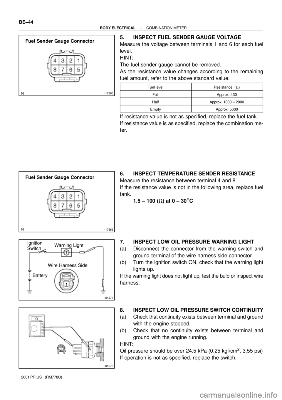
5. INSPECT FUEL SENDER GAUGE VOLTAGE
Measure the voltage between terminals 1 and 6 for each fuel
level.
HINT:
The fuel sender gauge cannot be removed.
As the resistance value changes according to the remaining
fuel amount, refer to the above standard value.
Fuel levelResistance (W)
FullApprox. 430
HalfApprox. 1000 ± 2000
EmptyApprox. 5000
If resistance value is not as specified, replace the fuel tank.
If resistance value is as specified, replace the combination me-
ter.
6. INSPECT TEMPERATURE SENDER RESISTANCE
Measure the resistance between terminal 4 and 8
If the resistance value is not in the following area, replace fuel
tank.
1.5 ± 100 (W) at 0 ± 30°C
7. INSPECT LOW OIL PRESSURE WARNING LIGHT
(a) Disconnect the connector from the warning switch and
ground terminal of the wire harness side connector.
(b) Turn the ignition switch ON, check that the warning light
lights up.
If the warning light does not light up, test the bulb or inspect wire
harness.
8. INSPECT LOW OIL PRESSURE SWITCH CONTINUITY
(a) Check that continuity exists between terminal and ground
with the engine stopped.
(b) Check that no continuity exists between terminal and
ground with the engine running.
HINT:
Oil pressure should be over 24.5 kPa (0.25 kgf/cm
2, 3.55 psi)
If operation is not as specified, replace the switch.
Page 1790 of 1943

BE1217
BatteryWarning Light
Ignition
Switch
I11650
BE0044
BatteryWarning Light
Ignition
Switch
Z11183
± BODY ELECTRICALCOMBINATION METER
BE±45
2001 PRIUS (RM778U)
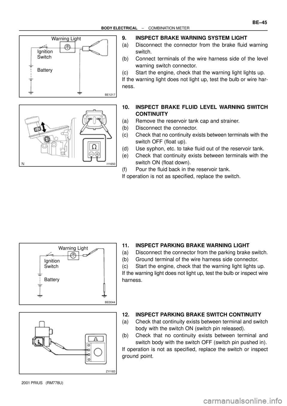
9. INSPECT BRAKE WARNING SYSTEM LIGHT
(a) Disconnect the connector from the brake fluid warning
switch.
(b) Connect terminals of the wire harness side of the level
warning switch connector.
(c) Start the engine, check that the warning light lights up.
If the warning light does not light up, test the bulb or wire har-
ness.
10. INSPECT BRAKE FLUID LEVEL WARNING SWITCH
CONTINUITY
(a) Remove the reservoir tank cap and strainer.
(b) Disconnect the connector.
(c) Check that no continuity exists between terminals with the
switch OFF (float up).
(d) Use syphon, etc. to take fluid out of the reservoir tank.
(e) Check that continuity exists between terminals with the
switch ON (float down).
(f) Pour the fluid back in the reservoir tank.
If operation is not as specified, replace the switch.
11. INSPECT PARKING BRAKE WARNING LIGHT
(a) Disconnect the connector from the parking brake switch.
(b) Ground terminal of the wire harness side connector.
(c) Start the engine, check that the warning light lights up.
If the warning light does not light up, test the bulb or inspect wire
harness.
12. INSPECT PARKING BRAKE SWITCH CONTINUITY
(a) Check that continuity exists between terminal and switch
body with the switch ON (switch pin released).
(b) Check that no continuity exists between terminal and
switch body with the switch OFF (switch pin pushed in).
If operation is not as specified, replace the switch or inspect
ground point.
Page 1791 of 1943
BE0044
BatteryWarning Light
Ignition
Switch BE±46
± BODY ELECTRICALCOMBINATION METER
2001 PRIUS (RM778U)
13. INSPECT OPEN DOOR WARNING LIGHT
Disconnect the connector from the door courtesy switch, and
ground terminal 1 of the wire harness side connector and check
that the warning light lights up.
If the warning light does not light up, inspect the bulb or wire har-
ness.