Page 596 of 1943

SS1HI±01
± SERVICE SPECIFICATIONSHYBRID VEHICLE CONTROL
SS±21
2001 PRIUS (RM778U)
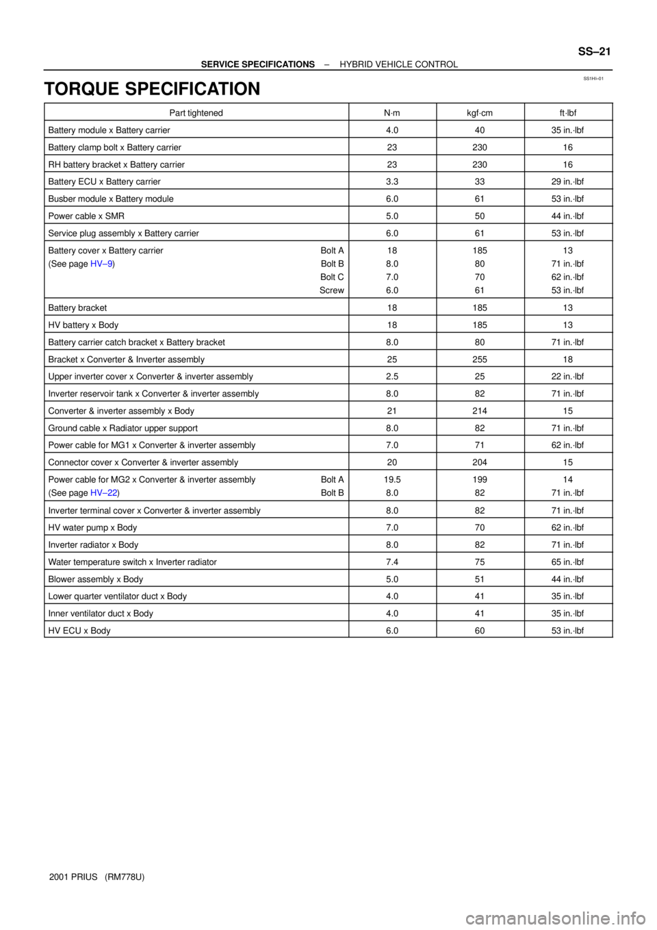
TORQUE SPECIFICATION
Part tightenedN´mkgf´cmft´lbf
Battery module x Battery carrier4.04035 in.´lbf
Battery clamp bolt x Battery carrier2323016
RH battery bracket x Battery carrier2323016
Battery ECU x Battery carrier3.33329 in.´lbf
Busber module x Battery module6.06153 in.´lbf
Power cable x SMR5.05044 in.´lbf
Service plug assembly x Battery carrier6.06153 in.´lbf
Battery cover x Battery carrier Bolt A
(See page HV±9) Bolt B
Bolt C
Screw18
8.0
7.0
6.0185
80
70
6113
71 in.´lbf
62 in.´lbf
53 in.´lbf
Battery bracket1818513
HV battery x Body1818513
Battery carrier catch bracket x Battery bracket8.08071 in.´lbf
Bracket x Converter & Inverter assembly2525518
Upper inverter cover x Converter & inverter assembly2.52522 in.´lbf
Inverter reservoir tank x Converter & inverter assembly8.08271 in.´lbf
Converter & inverter assembly x Body2121415
Ground cable x Radiator upper support8.08271 in.´lbf
Power cable for MG1 x Converter & inverter assembly7.07162 in.´lbf
Connector cover x Converter & inverter assembly2020415
Power cable for MG2 x Converter & inverter assembly Bolt A
(See page HV±22) Bolt B19.5
8.0199
8214
71 in.´lbf
Inverter terminal cover x Converter & inverter assembly8.08271 in.´lbf
HV water pump x Body7.07062 in.´lbf
Inverter radiator x Body8.08271 in.´lbf
Water temperature switch x Inverter radiator7.47565 in.´lbf
Blower assembly x Body5.05144 in.´lbf
Lower quarter ventilator duct x Body4.04135 in.´lbf
Inner ventilator duct x Body4.04135 in.´lbf
HV ECU x Body6.06053 in.´lbf
Page 1386 of 1943

DI7S3±01
± DIAGNOSTICSAIR CONDITIONING SYSTEM
DI±879
2001 PRIUS (RM778U)
PROBLEM SYMPTOMS TABLE
SymptomSuspect AreaSee page
Whole function of the does not operate3. A/C amplifier
4. IG power source circuitIN±41
DI±916
Air Flow Control: No blower operation1. IG power source circuit
2. Heater main relay circuit
3. Blower motor circuit
4. A/C amplifierDI±916
DI±921
DI±924
IN±41
Air Flow Control: No blower control1. Heater main relay circuit
2. Blower motor circuit
3. A/C amplifierDI±921
DI±924
IN±41
Air Flow Control: Insufficient air flow1. Blower motor circuitDI±924
Temperature Control: No cool air comes out1. Refrigerant volume
2. Drive belt tension
3. Refrigeration system inspection with manifold gauge set
4. Compressor circuit
5. Pressure switch circuit
6. Compressor lock sensor circuit
7. Air mix damper position sensor circuit
8. Air mix damper control servomotor circuit
9. Room temperature sensor circuit
10.Ambient temperature sensor circuit
11. A/C amplifierAC±3
AC±15
AC±3
DI±927
DI±894
DI±891
DI±897
DI±906
DI±874
DI±879
IN±41
Temperature Control: No warm air comes out1. Air mix damper position sensor circuit
2. Air mix damper control servomotor circuit
3. DC/DC converter circuit
4. PTC heater circuit
5. Room temperature sensor circuit
6. Ambient temperature sensor circuit
7. Evaporator temperature sensor circuit
8. A/C amplifierDI±897
DI±906
DI±934
DI±937,
DI±942
DI±876
DI±882
DI±885
IN±41
Temperature Control: Output air is warmer or cooler that the set
temperature or response is slow1. Refrigerant volume
2. Drive belt tension
3. Refrigeration system inspection with manifold gauge set
4. Radiator fan and condenser fan circuit
5. Solar sensor circuit
6. Room temperature sensor circuit
7. Ambient temperature sensor circuit
8. Evaporator temperature sensor circuit
9. Air mix damper position sensor circuit
10.Air mix damper control servomotor circuit
11. Evaporator
12.Heater radiator
13.Expansion valve
14.A/C amplifierAC±3
AC±15
AC±3
DI±947
DI±888
DI±876
DI±879
DI±885
DI±897
DI±906
AC±28
AC±28
AC±52
IN±41
Temperature Control: No temperature control (only Max. cool or
Max. warm)1. Room temperature sensor circuit
2. Ambient temperature sensor circuit
3. Air mix damper position sensor circuit
4. Air mix damper control servomotor circuit
5. A/C amplifierDI±876
DI±882
DI±897
DI±906
IN±41
No air inlet control1. Air inlet damper position sensor circuit
2. Air inlet damper control servomotor circuit
3. A/C amplifierDI±900
DI±909
IN±41
Page 1453 of 1943
I18393
DI±946
± DIAGNOSTICSAIR CONDITIONING SYSTEM
2001 PRIUS (RM778U)
5 Check harness and connector between A/C amplifier and HTR1 and HTR2 fuses
(See page IN±41).
NG Check and replace harness and connector.
OK
Check and replace A/C amplifier.
6 Check PTC heater.
PREPARATION:
Remove the heater radiator (See page AC±51).
CHECK:
Check continuity between terminals of PTC heater connector,
as shown in the chart.
OK:
Tester connectionResult
1 ± 2Continuity
3 ± 4Continuity
NG Replace heater radiator.
OK
Check harness and connector between PTC heater and HTR1, HT2 relays, PTC heater and body
ground (See page IN±41).
Page 1454 of 1943
± DIAGNOSTICSAIR CONDITIONING SYSTEM
DI±947
2001 PRIUS (RM778U)
PTC Heater Circuit (Heater Radiator)
CIRCUIT DESCRIPTION
A/C amplifier switches the HTR1 relay and HTR2 relay ON by signal from the A/C amplifier. It supplies power
to PTC heater (Heater radiator).
DI7SQ±01
Page 1458 of 1943
I18395
± DIAGNOSTICSAIR CONDITIONING SYSTEM
DI±951
2001 PRIUS (RM778U)
5 Check harness and connector between A/C amplifier and HTR3 fuse (See page
IN±41).
NG Check and replace harness and connector.
OK
Check and replace A/C amplifier.
6 Check PTC heater (Heater Radiator).
PREPARATION:
Remove the heater radiator (See page AC±27).
CHECK:
Check continuity between terminals of PTC heater connector.
OK:
Continuity exists.
NG Replace heater radiator.
OK
Check harness and connector between PTC heater and HTR3 relay, PTC heater and body ground
(See page IN±41).
Page 1459 of 1943
DI±952
± DIAGNOSTICSAIR CONDITIONING SYSTEM
2001 PRIUS (RM778U)
Radiator Fan and Condenser Fan Circuit
CIRCUIT DESCRIPTION
The electric fan speed is controlled as described below, in accordance with the following signals:
�ON/OFF signal of A/C switch
�ON/OFF signal detected by the pressure switch (that cut out at medium pressure)
�ON/OFF signal detected by water temperature switch
DI7SR±01
Page 1460 of 1943
I18401
A/C Amplifier
CF Engine Room J/B
Fan No.2 Relay
A9
A91
2RF IE16
R±W R±W
1J
1A
1J
1K
1J
1K
1B
1J
1K 1K 10
11
5
3
12
5
2
3
4
7 Fan No.1 Relay
Fan No.1 Relay1
2
5 3
4
1
2
5
3
3 5
12
CDS FAN
RDIV±YJ27
J28J27 EE
E J/C L±W To Engine ECU
W±B
V±Y
From
DC/DC Fuse
From ECU±
IG Fuse 1
1 2 R1 Radiator Fan Motor
W4 Water Temp. Switch12
W±B
W±BA3 A/C Pressure Switch2 3
J1
J/CJ7
J/C
AA A
AW±BW±B
IEV±Y
A1
A/C Condenser
Fan Motor
G±W
W±G
W
L±W2
W±B W±B
± DIAGNOSTICSAIR CONDITIONING SYSTEM
DI±953
2001 PRIUS (RM778U)
WIRING DIAGRAM
Page 1490 of 1943

A12943
1
2973
4
3
368
5
A11228
1
23
45
67
8
9
10
A12944
± ENGINE MECHANICALCYLINDER HEAD
EM±31
2001 PRIUS (RM778U)
�Do not disassembly the valve timing controller as-
sembly.
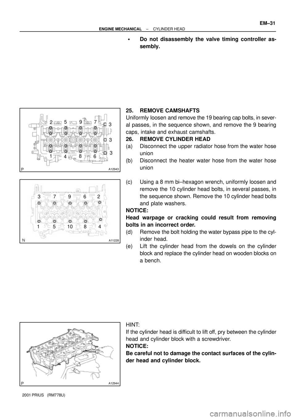
25. REMOVE CAMSHAFTS
Uniformly loosen and remove the 19 bearing cap bolts, in sever-
al passes, in the sequence shown, and remove the 9 bearing
caps, intake and exhaust camshafts.
26. REMOVE CYLINDER HEAD
(a) Disconnect the upper radiator hose from the water hose
union
(b) Disconnect the heater water hose from the water hose
union
(c) Using a 8 mm bi±hexagon wrench, uniformly loosen and
remove the 10 cylinder head bolts, in several passes, in
the sequence shown. Remove the 10 cylinder head bolts
and plate washers.
NOTICE:
Head warpage or cracking could result from removing
bolts in an incorrect order.
(d) Remove the bolt holding the water bypass pipe to the cyl-
inder head.
(e) Lift the cylinder head from the dowels on the cylinder
block and replace the cylinder head on wooden blocks on
a bench.
HINT:
If the cylinder head is difficult to lift off, pry between the cylinder
head and cylinder block with a screwdriver.
NOTICE:
Be careful not to damage the contact surfaces of the cylin-
der head and cylinder block.