Page 606 of 1943

SS16Z±08
± SERVICE SPECIFICATIONSSTEERING
SS±31
2001 PRIUS (RM778U)
TORQUE SPECIFICATION
Part tightenedN´mkgf´cmft´lbf
TILT STEERING COLUMN
Adjusting nut131309
No. 2 tilt lever lock bolt5.45548 in.´lbf
Tilt steering support lock nut9.510087 in.´lbf
Main shaft lower dust seal4.95043 in.´lbf
Column assembly set bolt and nut2526019
No. 2 intermediate shaft assembly x Main shaft assembly3536026
No. 2 intermediate shaft assembly x Intermediate extension3536026
Shift lock computer sub±assembly4.04035 in.´lbf
Steering wheel set nut5051037
Steering wheel pad set screw (Torx screw)8.89078 in.´lbf
POWER STEERING GEAR
Rack end x Steering rack62 (83)630 (850)46 (61)
Tie rod end lock nut5657041
PS gear assembly set bolt8385061
Stabilizer bar set bolt1919014
Suspension member137
1421,400
1,450101
105
Torque rod set nut1001,02074
EMPS bracket set bolt5.56052 in.´lbf
Lower suspension arm x Lower ball joint1421,450105
Stabilizer bar link set nut7476055
Tie rod end x Steering knuckle4950036
( ): For use without SST
Page 1035 of 1943
F12396
TOYOTA
Hand±held Tester
DLC3
DI±462
± DIAGNOSTICSELECTRIC MOTOR POWER STEERING
2001 PRIUS (RM778U)
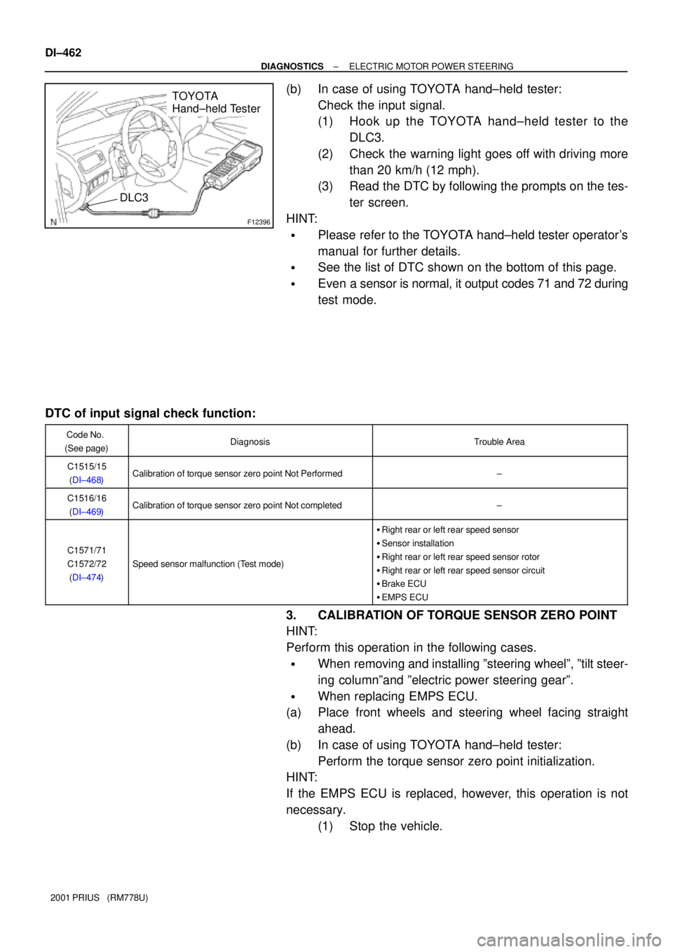
(b) In case of using TOYOTA hand±held tester:
Check the input signal.
(1) Hook up the TOYOTA hand±held tester to the
DLC3.
(2) Check the warning light goes off with driving more
than 20 km/h (12 mph).
(3) Read the DTC by following the prompts on the tes-
ter screen.
HINT:
�Please refer to the TOYOTA hand±held tester operator's
manual for further details.
�See the list of DTC shown on the bottom of this page.
�Even a sensor is normal, it output codes 71 and 72 during
test mode.
DTC of input signal check function:
Code No.
(See page)DiagnosisTrouble Area
C1515/15
(DI±468)Calibration of torque sensor zero point Not Performed±
C1516/16
(DI±469)Calibration of torque sensor zero point Not completed±
C1571/71
C1572/72
(DI±474)
Speed sensor malfunction (Test mode)
�Right rear or left rear speed sensor
�Sensor installation
�Right rear or left rear speed sensor rotor
�Right rear or left rear speed sensor circuit
�Brake ECU
�EMPS ECU
3. CALIBRATION OF TORQUE SENSOR ZERO POINT
HINT:
Perform this operation in the following cases.
�When removing and installing ºsteering wheelº, ºtilt steer-
ing columnºand ºelectric power steering gearº.
�When replacing EMPS ECU.
(a) Place front wheels and steering wheel facing straight
ahead.
(b) In case of using TOYOTA hand±held tester:
Perform the torque sensor zero point initialization.
HINT:
If the EMPS ECU is replaced, however, this operation is not
necessary.
(1) Stop the vehicle.
Page 1036 of 1943
F12396
TOYOTA
Hand±held Tester
DLC3
F12827
Tc
CG
Ts
F12864
Tc
CG
± DIAGNOSTICSELECTRIC MOTOR POWER STEERING
DI±463
2001 PRIUS (RM778U)
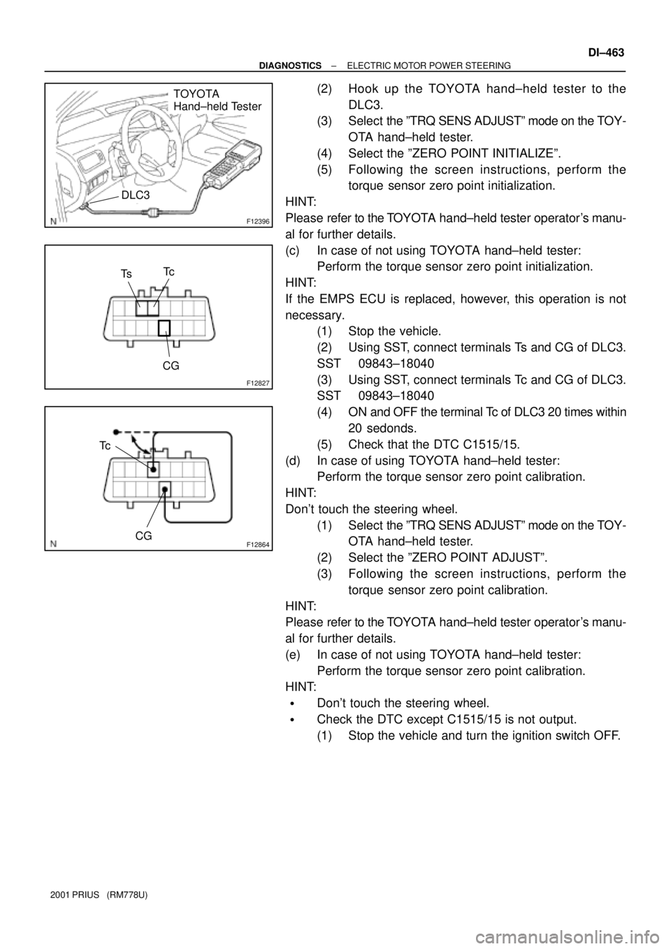
(2) Hook up the TOYOTA hand±held tester to the
DLC3.
(3) Select the ºTRQ SENS ADJUSTº mode on the TOY-
OTA hand±held tester.
(4) Select the ºZERO POINT INITIALIZEº.
(5) Following the screen instructions, perform the
torque sensor zero point initialization.
HINT:
Please refer to the TOYOTA hand±held tester operator's manu-
al for further details.
(c) In case of not using TOYOTA hand±held tester:
Perform the torque sensor zero point initialization.
HINT:
If the EMPS ECU is replaced, however, this operation is not
necessary.
(1) Stop the vehicle.
(2) Using SST, connect terminals Ts and CG of DLC3.
SST 09843±18040
(3) Using SST, connect terminals Tc and CG of DLC3.
SST 09843±18040
(4) ON and OFF the terminal Tc of DLC3 20 times within
20 sedonds.
(5) Check that the DTC C1515/15.
(d) In case of using TOYOTA hand±held tester:
Perform the torque sensor zero point calibration.
HINT:
Don't touch the steering wheel.
(1) Select the ºTRQ SENS ADJUSTº mode on the TOY-
OTA hand±held tester.
(2) Select the ºZERO POINT ADJUSTº.
(3) Following the screen instructions, perform the
torque sensor zero point calibration.
HINT:
Please refer to the TOYOTA hand±held tester operator's manu-
al for further details.
(e) In case of not using TOYOTA hand±held tester:
Perform the torque sensor zero point calibration.
HINT:
�Don't touch the steering wheel.
�Check the DTC except C1515/15 is not output.
(1) Stop the vehicle and turn the ignition switch OFF.
Page 1510 of 1943
A13906
N´m (kgf´cm, ft´lbf) : Specified torque
16 (163, 12)
Engine Unit
Fly Wheel
x6Damper Disc
x6 Damper Disc Spring
Transaxle
Non±reusable part
��
49 (500, 36)
See page EM±58 1st:
2nd: 90°
33 (337, 24)
EM±52
± ENGINE MECHANICALENGINE UNIT
1168 Author�: Date�:
2001 PRIUS (RM778U)
Page 1515 of 1943
EM1J2±02
P08755
A13917
SSTSST
1
2
3
4
6
5
A13940
SST
A13917
SSTSST
1
2
3
4
6
5
EM±58
± ENGINE MECHANICALENGINE UNIT
2001 PRIUS (RM778U)
INSTALLATION
1. INSTALL FLYWHEEL
(a) Apply adhesive to 2 or 3 threads of the bolt end.
Adhesive: Part No. 08833±00070, THREE BOND 1324
or equivalent
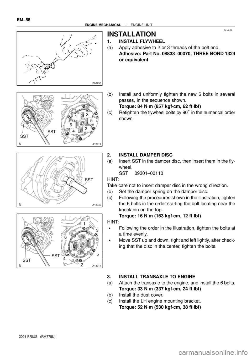
(b) Install and uniformly tighten the new 6 bolts in several
passes, in the sequence shown.
Torque: 84 N´m (857 kgf´cm, 62 ft´lbf)
(c) Retighten the flywheel bolts by 90° in the numerical order
shown.
2. INSTALL DAMPER DISC
(a) Insert SST in the damper disc, then insert them in the fly-
wheel.
SST 09301±00110
HINT:
Take care not to insert damper disc in the wrong direction.
(b) Set the damper spring on the damper disc.
(c) Following the procedures shown in the illustration, tighten
the 6 bolts in the order starting the bolt locating near the
knock pin on the top.
Torque: 16 N´m (163 kgf´cm, 12 ft´lbf)
HINT:
�Following the order in the illustration, tighten the bolts at
a time evenly.
�Move SST up and down, right and left lightly, after check-
ing that the disc in the center, tighten the bolts.
3. INSTALL TRANSAXLE TO ENGINE
(a) Attach the transaxle to the engine, and install the 6 bolts.
Torque: 33 N´m (337 kgf´cm, 24 ft´lbf)
(b) Install the dust cover.
(c) Install the LH engine mounting bracket.
Torque: 52 N´m (530 kgf´cm, 38 ft´lbf)
Page 1657 of 1943
F07326
� �
1
2
: Use with adjusting bolt
F12938
Bolt
Adjusting
ValueSet BoltAdjusting Bolt90105±15001 90105±15004 90105±15005 90105±15006
121212121 Dot
2 Dots3 Dots
±1°30' ± ±1°15'
±1°15' ± ±1°00'
±1°00' ± ±45'
±45' ± ±30'
±30' ± ±15'
0' ± 15'
15' ± 30'
30' ± 45'
45' ± 1°00'
1°00' ± 1°15' ±15' ± 0'
1°15' ± 1°30'
± SUSPENSION AND AXLEFRONT WHEEL ALIGNMENT
SA±5
1455 Author�: Date�:
2001 PRIUS (RM778U)
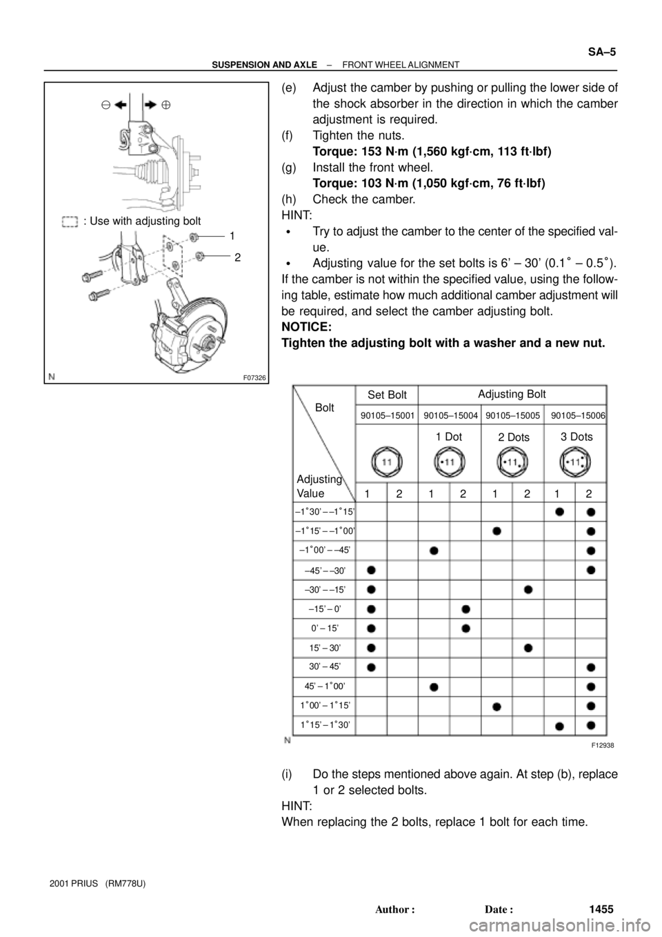
(e) Adjust the camber by pushing or pulling the lower side of
the shock absorber in the direction in which the camber
adjustment is required.
(f) Tighten the nuts.
Torque: 153 N´m (1,560 kgf´cm, 113 ft´lbf)
(g) Install the front wheel.
Torque: 103 N´m (1,050 kgf´cm, 76 ft´lbf)
(h) Check the camber.
HINT:
�Try to adjust the camber to the center of the specified val-
ue.
�Adjusting value for the set bolts is 6' ± 30' (0.1° ± 0.5°).
If the camber is not within the specified value, using the follow-
ing table, estimate how much additional camber adjustment will
be required, and select the camber adjusting bolt.
NOTICE:
Tighten the adjusting bolt with a washer and a new nut.
(i) Do the steps mentioned above again. At step (b), replace
1 or 2 selected bolts.
HINT:
When replacing the 2 bolts, replace 1 bolt for each time.
Page 1658 of 1943
SA3213
Front A
DB
C
F11574
F11575
SA0028
Front AB
A B
A: Inside
B: Outside SA±6
± SUSPENSION AND AXLEFRONT WHEEL ALIGNMENT
1456 Author�: Date�:
2001 PRIUS (RM778U)
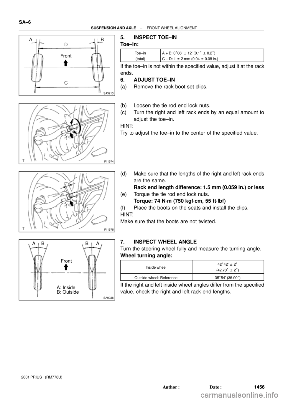
5. INSPECT TOE±IN
Toe±in:
Toe±in
(total)A + B: 0°06' ± 12' (0.1° ± 0.2°)
C ± D: 1 ± 2 mm (0.04 ± 0.08 in.)
If the toe±in is not within the specified value, adjust it at the rack
ends.
6. ADJUST TOE±IN
(a) Remove the rack boot set clips.
(b) Loosen the tie rod end lock nuts.
(c) Turn the right and left rack ends by an equal amount to
adjust the toe±in.
HINT:
Try to adjust the toe±in to the center of the specified value.
(d) Make sure that the lengths of the right and left rack ends
are the same.
Rack end length difference: 1.5 mm (0.059 in.) or less
(e) Torque the tie rod end lock nuts.
Torque: 74 N´m (750 kgf´cm, 55 ft´lbf)
(f) Place the boots on the seats and install the clips.
HINT:
Make sure that the boots are not twisted.
7. INSPECT WHEEL ANGLE
Turn the steering wheel fully and measure the turning angle.
Wheel turning angle:
Inside wheel42°42' ± 2°
(42.70° ± 2°)
Outside wheel: Reference35°54' (35.90°)
If the right and left inside wheel angles differ from the specified
value, check the right and left rack end lengths.
Page 1659 of 1943
SA1ZR±01
F08617
R14731
Backlash:Deviation:
F12940SST
± SUSPENSION AND AXLEFRONT AXLE HUB
SA±9
2001 PRIUS (RM778U)
REMOVAL
1. REMOVE FRONT WHEEL
Torque: 103 N´m (1,050 kgf´cm, 76 ft´lbf)
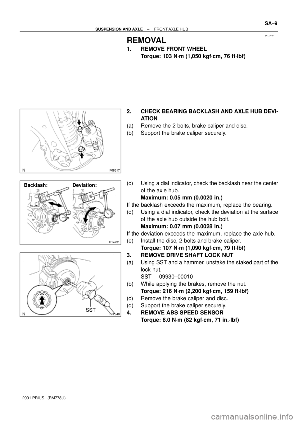
2. CHECK BEARING BACKLASH AND AXLE HUB DEVI-
ATION
(a) Remove the 2 bolts, brake caliper and disc.
(b) Support the brake caliper securely.
(c) Using a dial indicator, check the backlash near the center
of the axle hub.
Maximum: 0.05 mm (0.0020 in.)
If the backlash exceeds the maximum, replace the bearing.
(d) Using a dial indicator, check the deviation at the surface
of the axle hub outside the hub bolt.
Maximum: 0.07 mm (0.0028 in.)
If the deviation exceeds the maximum, replace the axle hub.
(e) Install the disc, 2 bolts and brake caliper.
Torque: 107 N´m (1,090 kgf´cm, 79 ft´lbf)
3. REMOVE DRIVE SHAFT LOCK NUT
(a) Using SST and a hammer, unstake the staked part of the
lock nut.
SST 09930±00010
(b) While applying the brakes, remove the nut.
Torque: 216 N´m (2,200 kgf´cm, 159 ft´lbf)
(c) Remove the brake caliper and disc.
(d) Support the brake caliper securely.
4. REMOVE ABS SPEED SENSOR
Torque: 8.0 N´m (82 kgf´cm, 71 in.´lbf)