Page 1663 of 1943

SA20B±01
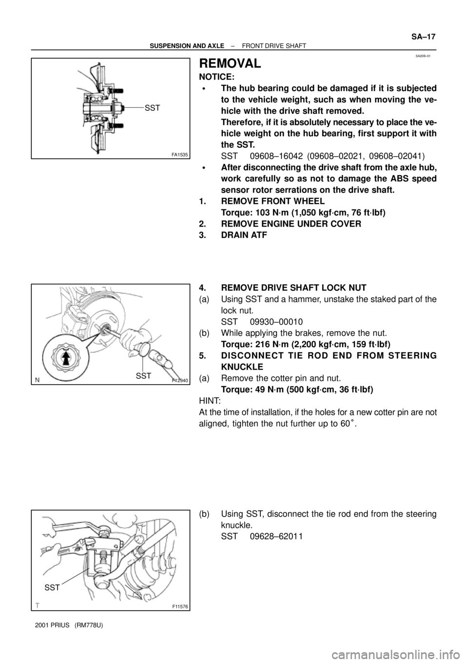
FA1535
SST
F12940SST
F11576
SST
± SUSPENSION AND AXLEFRONT DRIVE SHAFT
SA±17
2001 PRIUS (RM778U)
REMOVAL
NOTICE:
�The hub bearing could be damaged if it is subjected
to the vehicle weight, such as when moving the ve-
hicle with the drive shaft removed.
Therefore, if it is absolutely necessary to place the ve-
hicle weight on the hub bearing, first support it with
the SST.
SST 09608±16042 (09608±02021, 09608±02041)
�After disconnecting the drive shaft from the axle hub,
work carefully so as not to damage the ABS speed
sensor rotor serrations on the drive shaft.
1. REMOVE FRONT WHEEL
Torque: 103 N´m (1,050 kgf´cm, 76 ft´lbf)
2. REMOVE ENGINE UNDER COVER
3. DRAIN ATF
4. REMOVE DRIVE SHAFT LOCK NUT
(a) Using SST and a hammer, unstake the staked part of the
lock nut.
SST 09930±00010
(b) While applying the brakes, remove the nut.
Torque: 216 N´m (2,200 kgf´cm, 159 ft´lbf)
5. DISCONNECT TIE ROD END FROM STEERING
KNUCKLE
(a) Remove the cotter pin and nut.
Torque: 49 N´m (500 kgf´cm, 36 ft´lbf)
HINT:
At the time of installation, if the holes for a new cotter pin are not
aligned, tighten the nut further up to 60°.
(b) Using SST, disconnect the tie rod end from the steering
knuckle.
SST 09628±62011
Page 1671 of 1943

SA1ZW±01
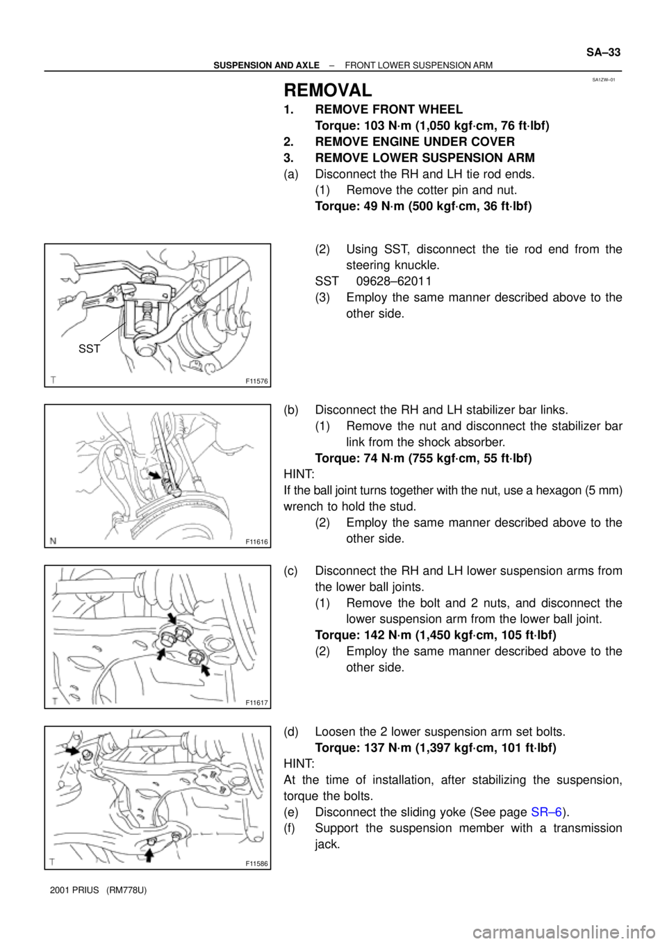
F11576
SST
F11616
F11617
F11586
± SUSPENSION AND AXLEFRONT LOWER SUSPENSION ARM
SA±33
2001 PRIUS (RM778U)
REMOVAL
1. REMOVE FRONT WHEEL
Torque: 103 N´m (1,050 kgf´cm, 76 ft´lbf)
2. REMOVE ENGINE UNDER COVER
3. REMOVE LOWER SUSPENSION ARM
(a) Disconnect the RH and LH tie rod ends.
(1) Remove the cotter pin and nut.
Torque: 49 N´m (500 kgf´cm, 36 ft´lbf)
(2) Using SST, disconnect the tie rod end from the
steering knuckle.
SST 09628±62011
(3) Employ the same manner described above to the
other side.
(b) Disconnect the RH and LH stabilizer bar links.
(1) Remove the nut and disconnect the stabilizer bar
link from the shock absorber.
Torque: 74 N´m (755 kgf´cm, 55 ft´lbf)
HINT:
If the ball joint turns together with the nut, use a hexagon (5 mm)
wrench to hold the stud.
(2) Employ the same manner described above to the
other side.
(c) Disconnect the RH and LH lower suspension arms from
the lower ball joints.
(1) Remove the bolt and 2 nuts, and disconnect the
lower suspension arm from the lower ball joint.
Torque: 142 N´m (1,450 kgf´cm, 105 ft´lbf)
(2) Employ the same manner described above to the
other side.
(d) Loosen the 2 lower suspension arm set bolts.
Torque: 137 N´m (1,397 kgf´cm, 101 ft´lbf)
HINT:
At the time of installation, after stabilizing the suspension,
torque the bolts.
(e) Disconnect the sliding yoke (See page SR±6).
(f) Support the suspension member with a transmission
jack.
Page 1673 of 1943
SA1ZU±01
F11598
SST
F11599
F11593
Wood
F11618
± SUSPENSION AND AXLEREAR SHOCK ABSORBER
SA±51
2001 PRIUS (RM778U)
REMOVAL
1. REMOVE REAR WHEELS
Torque: 103 N´m (250 kgf´cm, 18 ft´lbf)
2. REMOVE REAR SEAT (See page BO±83)
3. DISCONNECT BRAKE LINES
(a) Using SST, disconnect the brake lines from the flexible
hose. Use a container to catch brake fluid as it drains out.
SST 09751±36011
(b) Remove the clip.
(c) Employ the same manner described above to the other
side.
4. DISCONNECT ABS SPEED SENSOR WIRE HARNESS
Remove the 4 nuts, and disconnect the ABS speed sensor wire
harness from the axle beam.
Torque: 5.4 N´m (55 kgf´cm, 48 in.´lbf)
5. SUPPORT REAR AXLE BEAM AT RIGHT AND LEFT
SIDES WITH JACKS
6. REMOVE SHOCK ABSORBER
(a) Remove the 2 nuts and bolt.
Torque: 80 N´m (816 kgf´cm, 59 ft´lbf)
Page 1679 of 1943

BR1J6±01
BR±4
± BRAKEBRAKE FLUID
1519 Author�: Date�:
2001 PRIUS (RM778U)
BRAKE FLUID
BLEEDING
HINT:
�If any work is done on the brake system or if air in the
brake lines is suspected, bleed the air from the system.
�When bleeding, keep the amount of the fluid within the
line of reservoir between Min. and Max.
NOTICE:
�Do not let brake fluid remain on painted surfaces.
Wash it off immediately.
�With the reservoir cap removed, when depressing the
brake pedal, the fluid will spray.
1. FILL RESERVOIR WITH BRAKE FLUID
Fluid: SAE J1703 or FMVSS NO. 116 DOT3
2. RELEASE PRESSURE FROM POWER SUPPLY SYS-
TEM
HINT:
If the hydraulic brake booster has been disassembled, discon-
nect the brake line from the hydraulic brake booster or if the res-
ervoir becomes empty, bleed the hydraulic brake booster.
(a) Turn the ignition switch OFF, depress the brake pedal
more than 40 times.
(b) Turn the ignition switch ON, check that the pump stops af-
ter 30 to 40 seconds.
NOTICE:
When the pump does not stop, repeat step (a) and (b) again.
3. BLEED AIR
(a) Turning the ignition switch OFF, bleed the right and left
front brake caliper.
HINT:
Perform air bleeding for each wheel, depress the brake pedal
more than 20 times or more for each.
(b) Turning the ignition switch ON, check that the pump motor
stops.
(c) Fully open the bleeder plug of the right or left rear brake
cylinder and drain the fluid while depressing the brake
pedal for 3 seconds.
HINT:
�Perform air bleeding for both wheels on the right or left
side and then do the same on the other side.
�It is not necessary to depress the pedal continuously, as
brake fluid flows out by first depressing.
(d) Release the brake pedal and wait until the pump motor
stops.
(e) Repeat step (c) and (d) 7 times or more.
(f) Tighten the bleeder plug of the rear brake cylinder.
Torque: 8.5 N´m (87 kgf´cm, 75 in.´lbf)
(g) While depressing the brake pedal, let air out from the rear
brake cylinder mentioned in (f).
Page 1682 of 1943
BR1JA±01
F12629
Front Door Scuff Plate Cowl Side TrimHood Lock Release
Lever Lower Column CoverRadio Tuner Opening CoverCluster Finish Panel
Assembly Hazard Warning Switch
Lower Center Cluster
Finish PanelGlove Compartment
Door Finish PanelInstrument PanelNo. 3 Register No. 2 Side Defroster
Nozzle
Front Pillar GarnishPassenger Air Bag
Assembly Cluster Finish Panel
Combination Meter
Lower Finish PanelSteering Wheel Pad Steering Wheel
Spiral CableUpper Column Cover
Front Door Scuff PlateCowl Side Trim No. 1 RegisterNo. 1 Side Defroster
NozzleFront Pillar Garnish
: Specified torqueN´m (kgf´cm, ft´lbf)
50 (510, 37)
BR±10
± BRAKEPARKING BRAKE PEDAL
2001 PRIUS (RM778U)
COMPONENTS
Page 1687 of 1943
F12060
± BRAKEFRONT BRAKE PAD
BR±25
2001 PRIUS (RM778U)
9. INSTALL CALIPER
(a) Draw out a small amount of brake fluid from the reservoir.
(b) Press in the piston with a hammer handle or similar imple-
ment.
HINT:
�Tape the hammer handle before use.
�If the piston is difficult to push in, loosen the bleeder plug
and push in the piston while letting some brake fluid es-
cape.
(c) Install the caliper.
(d) Hold the sliding pin and torque the installation bolts.
Torque: 34 N´m (350 kgf´cm, 25 ft´lbf)
10. INSTALL FRONT WHEEL
Torque: 103 N´m (1,050 kgf´cm, 76 ft´lbf)
11. DEPRESS BRAKE PEDAL SEVERAL TIMES
12. CHECK THAT FLUID LEVEL IS AT MAX LINE
Page 1689 of 1943
F09780
F12390
SST
BR±34
± BRAKEREAR DRUM BRAKE
2001 PRIUS (RM778U)
(b) Using needle±nose pliers, disconnect the parking brake
cable from the parking brake lever, and remove the rear
shoe.
6. REMOVE PARKING BRAKE LEVER
(a) Remove the C±washer.
(b) Remove the parking brake lever from the rear shoe.
7. REMOVE WHEEL CYLINDER
(a) Using SST, disconnect the brake line. Use container to
catch the brake fluid.
SST 09751±36011
Torque: 15 N´m (155 kgf´cm, 11 ft´lbf)
(b) Remove the bolt and the wheel cylinder.
Torque: 10 N´m (100 kgf´cm, 7 ft´lbf)
8. DISASSEMBLE WHEEL CYLINDER
(a) Remove the 2 boots from the wheel cylinder.
(b) Remove the 2 pistons from the wheel cylinder.
(c) Remove the spring from the wheel cylinder.
(d) Remove the 2 piston cups from each piston.
Page 1698 of 1943
SR1BE±01
F12219
Shift Lever Assembly
Upper Column Cover
Lower Ciolumn CoverSteering Wheel Pad
Steering Wheel
Combination Switch
(w/ Spiral Cable)
Transmission Control
Cable Steering Column
Assembly
Shift Lock Computer
Sub±assembly Sliding Yoke
No. 2 Intermediate
Shaft Assembly
Column Hole Cover
Main Shaft Lower
Dust Seal
Hood Lock
Release LeverLower Instrument
Finish Panel
N´m (kgf´cm, ft´lbf): Specified torque
35 (360, 26)
25 (260, 19)
49 (50, 43 in.´lbf)
35 (360, 26)
35 (360, 26)
25 (260, 19)
50 (510, 37)
8.8 (90, 78 in.´lbf)
Torx Screw
8.0 (80, 69 in.´lbf)
8.8 (90, 78 in.´lbf)
Torx Screw
4.0 (40, 35 in.´lbf)
Instrument Finish
Panel
49 (50, 43 in.´lbf)
SR±4
± STEERINGTILT STEERING COLUMN
1577 Author�: Date�:
2001 PRIUS (RM778U)
TILT STEERING COLUMN
COMPONENTS