Page 711 of 1943
A03403A03404A03675
M+ Signal Waveform
5 V/
Division
GND
1 msec./Division
M± Signal Waveform
GND
5 V/
Division
1 msec./Division
± DIAGNOSTICSENGINE
DI±109
2001 PRIUS (RM778U)
1 Check throttle control motor circuit.
PREPARATION:
(a) Connect the oscilloscope between terminals M+ or M±
and E1 of the ECM connectors.
(b) Start the engine.
CHECK:
Check the waveform between terminals M+ or M± and E1 of the
ECM connectors when the engine is idling.
OK:
The correct waveforms are as shown.
HINT:
The waveform frequency varies depending on the throttle
opening.
OK Check and replace ECM (See page IN±41).
NG
2 Check throttle control motor (See page SF±24).
NG Replace throttle control motor with magnetic
clutch (See page SF±29).
OK
3 Check for open and short in harness and connector between throttle control mo-
tor and ECM (See page IN±41).
NG Repair or replace harness or connector.
OK
Check and replace ECM (See page IN±41).
Page 769 of 1943

FI7012A11860
P±G A/C Control Assembly
A8 E10522
ACTECM
± DIAGNOSTICSENGINE
DI±171
2001 PRIUS (RM778U)
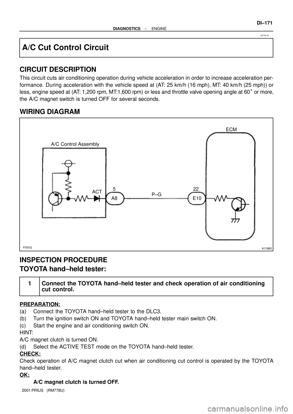
A/C Cut Control Circuit
CIRCUIT DESCRIPTION
This circuit cuts air conditioning operation during vehicle acceleration in order to increase acceleration per-
formance. During acceleration with the vehicle speed at (AT: 25 km/h (16 mph), MT: 40 km/h (25 mph)) or
less, engine speed at (AT: 1,200 rpm, MT:1,600 rpm) or less and throttle valve opening angle at 60° or more,
the A/C magnet switch is turned OFF for several seconds.
WIRING DIAGRAM
INSPECTION PROCEDURE
TOYOTA hand±held tester:
1 Connect the TOYOTA hand±held tester and check operation of air conditioning
cut control.
PREPARATION:
(a) Connect the TOYOTA hand±held tester to the DLC3.
(b) Turn the ignition switch ON and TOYOTA hand±held tester main switch ON.
(c) Start the engine and air conditioning switch ON.
HINT:
A/C magnet clutch is turned ON.
(d) Select the ACTIVE TEST mode on the TOYOTA hand±held tester.
CHECK:
Check operation of A/C magnet clutch cut when air conditioning cut control is operated by the TOYOTA
hand±held tester.
OK:
A/C magnet clutch is turned OFF.
DI7T8±01
Page 1406 of 1943
I08340
J1
J/CL±Y
A3
A/C Dual Pressure
SwitchA/C amplifier
W±B
IE1
A811
PSW
4
ED 115
A W±B
± DIAGNOSTICSAIR CONDITIONING SYSTEM
DI±899
2001 PRIUS (RM778U)
DTC 23 Pressure Switch Circuit
CIRCUIT DESCRIPTION
This pressure switch sends the appropriate signals to the A/C amplifier when the A/C refrigerant pressure
drops too low or rises too high. When the A/C amplifier receives these signals, if outputs signals via the A/C
amplifier to switch off the compressor relay and turns the magnetic clutch off.
DTC No.Detection ItemTrouble Area
�Open inpressure sensor circuit�Pressure switch
23
�Open in pressure sensor circuit.
�Abnormal refri
gerant pressure.
Pressure switch
�Harness or connector between pressure switch and A/C am-
lifi23�Abnormal refrigerant ressure.
below 196 kPa (2.0 kgf/cm2. 28 psi)2
plifier
�
Refrigerantpipe lineover 3,140 kPa (32.0 kgf/cm2. 455 psi)�Refrigerant pipe line
�A/C amplifier
WIRING DIAGRAM
DI7SB±01
Page 1439 of 1943
I18387
LG±R
IE18
1
F18
FL Block No. 2
BatteryInstrument Panel J/B
I15
Ignition
SW J6
J/C
AA E1022
1F3
1A5
2D6
2K8
3
2B Engine Room J/B
IG1 Relay ACT
B±Y 35
21
4
IG1
AM1
2 W
A
J11
J/C
ID MAINFL Block No. 1
F111
F131
1DC/DC
B±GW±BA/C Amplifier
A2
A/C Magnetic
Clutch W±G AM12H1 2D3 HTRCLR MG Relay
1F4 12
5
3A85
ACT
A8 10
MGC LG±R
B±L
IE113
R
R
R
J/C
J21A
J20C
R ECM DI±932
± DIAGNOSTICSAIR CONDITIONING SYSTEM
2001 PRIUS (RM778U)
Compressor Circuit
CIRCUIT DESCRIPTION
A/C amplifier switches the A/C magnetic clutch relay ON, thus turning the A/C compressor magnetic clutch
ON.
WIRING DIAGRAM
DI7SM±01
Page 1440 of 1943
I18169
MGC
(+)
(±) ON
Z18060
15 2
3
12 3 5
± DIAGNOSTICSAIR CONDITIONING SYSTEM
DI±933
2001 PRIUS (RM778U)
INSPECTION PROCEDURE
1 Check voltage between terminal MGC of A/C amplifier and body ground.
CHECK:
(a) Start engine.
(b) Push AUTO SW.
(c) Measure voltage between terminal MGC of A/C amplifier
connector and body ground when A/C switch is On and
OFF.
OK:
A/C switchVoltage
ONBelow 0.7 V
OFF10 ± 14 V
OK Go to step 5.
NG
2 Check magnetic clutch relay.
PREPARATION:
Remove magnetic clutch relay from engine room J/B.
CHECK:
Check continuity between each pair of terminals shown below
of magnetic clutch relay.
OK:
Tester connectionSpecified condition
1 ± 262.5 ± 90.9 W
3 ± 5No continuity
PREPARATION:
Apply battery positive (+) voltage between terminals 1 and 2.
CHECK:
Check continuity between terminals 3 and 5.
OK:
Continuity exists.
NG Replace magnetic clutch relay.
OK
Page 1441 of 1943
I18006
1
I18156
ACT
DI±934
± DIAGNOSTICSAIR CONDITIONING SYSTEM
2001 PRIUS (RM778U)
3 Check A/C magnetic clutch.
PREPARATION:
Disconnect magnetic clutch connector.
CHECK:
Connect positive (+) lead connected to battery to magnetic
clutch connector terminal 3 and negative (±) lead to body
ground.
OK:
Magnetic clutch is energized.
NG Repair A/C magnetic clutch.
OK
4 Check harness and connector between magnetic clutch relay and A/C amplifier,
A/C compressor and body ground (See page IN±41).
NG Repair or replace harness or connector.
OK
Proceed to next circuit inspection shown on
problem symptons table (See page DI±874).
5 Check voltage between terminal ACT of A/C amplifier connector side and body
ground.
PREPARATION:
(a) Disconnect A/C amplifier connector.
(b) Turn ignition switch ON.
CHECK:
Check voltage between terminal ACT of A/C amplifier harness
side connector.
OK:
Voltage : 10 ± 14 V
NG Check and replace engine ECU.
OK
Page 1442 of 1943
I18157
ACT(±) (+)
ON
± DIAGNOSTICSAIR CONDITIONING SYSTEM
DI±935
2001 PRIUS (RM778U)
6 Check voltage between terminal ACT of A/C amplifier connector and body
ground.
PREPARATION:
(a) Remove center cluster module control with connector still
connected.
(b) Start the engine and push AUTO switch.
CHECK:
Check the voltage between terminal ACT of A/C amplifier con-
nector and body ground when magnetic clutch is ON and OFF
by A/C switch.
OK:
Magnetic clutchVoltage
ON10 ± 14 V
OFFBelow 1.0 V
NG Check and replace A/C amplifier.
OK
7 Check harness and connector between magnetic clutch relay and A/C amplifier
(See page IN±41).
NG Repair or replace harness or connector.
OK
Proceed to next circuit inspection shown on
problem symptoms table (See page
DI±874).
Page 1444 of 1943

I18171
(+) (±)WP ON
Z18060
15 2
3
123 5
± DIAGNOSTICSAIR CONDITIONING SYSTEM
DI±937
2001 PRIUS (RM778U)
INSPECTION PROCEDURE
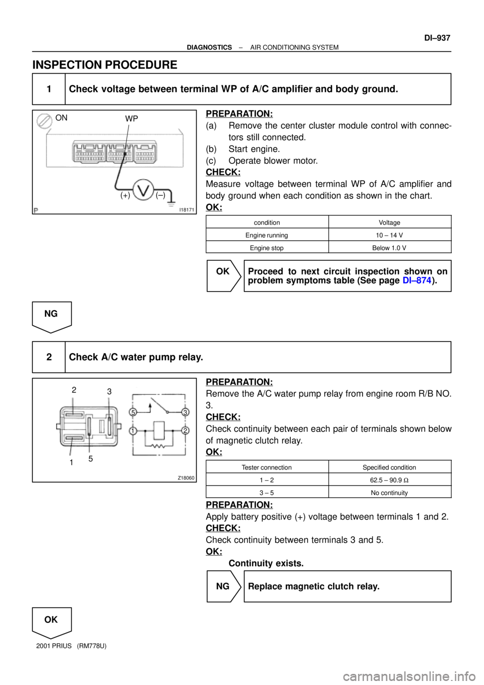
1 Check voltage between terminal WP of A/C amplifier and body ground.
PREPARATION:
(a) Remove the center cluster module control with connec-
tors still connected.
(b) Start engine.
(c) Operate blower motor.
CHECK:
Measure voltage between terminal WP of A/C amplifier and
body ground when each condition as shown in the chart.
OK:
conditionVoltage
Engine running10 ± 14 V
Engine stopBelow 1.0 V
OK Proceed to next circuit inspection shown on
problem symptoms table (See page DI±874).
NG
2 Check A/C water pump relay.
PREPARATION:
Remove the A/C water pump relay from engine room R/B NO.
3.
CHECK:
Check continuity between each pair of terminals shown below
of magnetic clutch relay.
OK:
Tester connectionSpecified condition
1 ± 262.5 ± 90.9 W
3 ± 5No continuity
PREPARATION:
Apply battery positive (+) voltage between terminals 1 and 2.
CHECK:
Check continuity between terminals 3 and 5.
OK:
Continuity exists.
NG Replace magnetic clutch relay.
OK