Page 1452 of 1943
I18396
Engine Room R/B No. 3
HTR3 Fuse
Z18060
15 2
3
123 5
± DIAGNOSTICSAIR CONDITIONING SYSTEM
DI±945
2001 PRIUS (RM778U)
3 Check HTR3 fuses.
PREPARATION:
Remove the HTR3 fuse from engine room R/B No. 3.
CHECK:
Check continuity of HTR1 and HTR2 fuses.
OK:
Continuity exists.
NG Check for short in all the harness and compo-
nents connected to the HTR1 and HTR2 fuses
(See attached wiring diagram).
OK
4 Check HTR3 relays.
PREPARATION:
Remove the HTR3 relays from engine room relay block No. 3.
CHECK:
Check continuity between each pair of terminals shown below
of magnetic clutch relay.
OK:
Tester connectionSpecified condition
1 ± 262.5 ± 90.9 W
3 ± 5No continuity
PREPARATION:
Apply battery positive (+) voltage between terminals 1 and 2.
CHECK:
Check continuity between terminals 3 and 5.
OK:
Continuity exists.
NG Replace HTR3 relay.
OK
Page 1457 of 1943
I18396
Engine Room R/B No. 3
HTR1 Fuse HTR2 Fuse
Z18060
15 2
3
123 5
DI±950
± DIAGNOSTICSAIR CONDITIONING SYSTEM
2001 PRIUS (RM778U)
3 Check HTR1 and HTR2 fuses.
PREPARATION:
Remove the HTR1 and HTR2 fuses from engine room R/B NO.
3.
CHECK:
Check continuity of HTR1 and HTR2 fuses.
OK:
Continuity exists.
NG Check for short in all the harness and compo-
nents connected to the HTR1 and HTR2 fuses
(See attached wiring diagram).
OK
4 Check HTR1 and HTR2 relays.
PREPARATION:
Remove the HTR1 and HTR2 relays from engine room relay
block NO. 3.
CHECK:
Check continuity between each pair of terminals shown below
of magnetic clutch relay.
OK:
Tester connectionSpecified condition
1 ± 262.5 ± 90.9 W
3 ± 5No continuity
PREPARATION:
Apply battery positive (+) voltage between terminals 1 and 2.
CHECK:
Check continuity between terminals 3 and 5.
OK:
Continuity exists.
NG Replace HTR1 and (or) HTR2 relay.
OK
Page 1915 of 1943
AC±10
± AIR CONDITIONINGAIR CONDITIONING SYSTEM
2001 PRIUS (RM778U)
4. INSPECT IDLE±UP SPEED
(a) Activate inspection mode (See page IN±10).
(b) Inspect idle±up speed when the these conditions are es-
tablished.
Test conditions:
�Idle speed set correctly.
�Steering wheel straight ahead
�Blower speed control dial at HI
�A/C switch ON
Magnetic clutch conditionIdle speed
Magnetic clutch not engaged1,000 ±50 rpm
Magnetic clutch engaged1,000 ±50 rpm
If idle speed is not as specified, check the engine ECU and
throttle body.
Page 1922 of 1943
AC35U±01
I11223
SST
I18010
SST
I18012
N20013
R±Shape
RotorSnap Ring
Compressor
I18011
AC±40
± AIR CONDITIONINGCOMPRESSOR AND MAGNETIC CLUTCH
2001 PRIUS (RM778U)
DISASSEMBLY
1. REMOVE PRESSURE PLATE
(a) Using SST and a socket wrench, remove the shaft bolt.
SST 07112±76050
Torque: 13.2 N´m (135 kgf´cm, 9 ft´lbf)
(b) Install SST to the pressure plate.
SST 07112±66040
(c) Using SST and a socket wrench, remove the pressure
plate.
SST 07112±76050, 07112±66040
(d) Remove the shims from the shaft.
2. REMOVE ROTOR
(a) Remove the snap ring.
NOTICE:
At the time of reassembly, please refer to the following
item.
The snap ring should be installed so that its beveled side
faces up.
(b) Using a plastic hammer, tap the rotor off the shaft.
NOTICE:
Be careful not to damage the pulley when tapping on the ro-
tor.
Page 1923 of 1943
I18013
I18014
N20012
R±Shape
Snap Ring
Startor
Compressor
N18359
± AIR CONDITIONINGCOMPRESSOR AND MAGNETIC CLUTCH
AC±41
2001 PRIUS (RM778U)
3. REMOVE STATOR
(a) Disconnect the connector from the stator.
(b) Remove the screw and stator lead wire.
(c) Remove the snap ring.
NOTICE:
At the time of reassembly, please refer to the following
item.
The snap ring should be installed so that its beveled side
faces up.
(d) Remove the stator.
Page 1928 of 1943

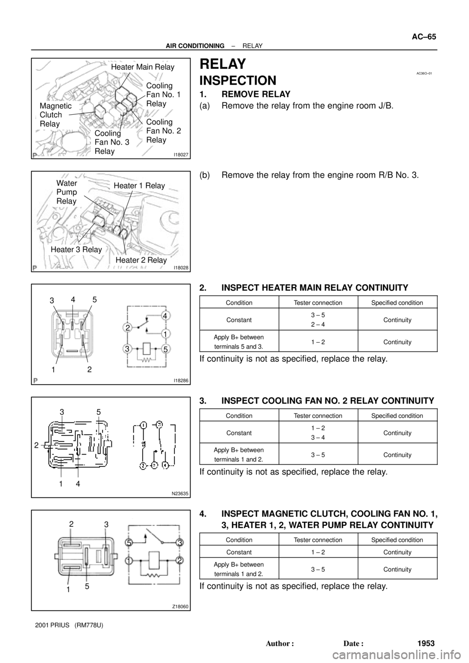
I18027
Heater Main Relay
Magnetic
Clutch
Relay
Cooling
Fan No. 3
Relay
Cooling
Fan No. 1
Relay
Cooling
Fan No. 2
Relay
AC36O±01
I18028Heater 2 Relay
Heater 1 Relay
Heater 3 Relay
Water
Pump
Relay
I18286
3
2
15 4
1 4
32
5
N23635
3
2
15
4
Z18060
13
2 5
5 2
3
1
± AIR CONDITIONINGRELAY
AC±65
1953 Author�: Date�:
2001 PRIUS (RM778U)
RELAY
INSPECTION
1. REMOVE RELAY
(a) Remove the relay from the engine room J/B.
(b) Remove the relay from the engine room R/B No. 3.
2. INSPECT HEATER MAIN RELAY CONTINUITY
ConditionTester connectionSpecified condition
Constant3 ± 5
2 ± 4Continuity
Apply B+ between
terminals 5 and 3.1 ± 2Continuity
If continuity is not as specified, replace the relay.
3. INSPECT COOLING FAN NO. 2 RELAY CONTINUITY
ConditionTester connectionSpecified condition
Constant1 ± 2
3 ± 4Continuity
Apply B+ between
terminals 1 and 2.3 ± 5Continuity
If continuity is not as specified, replace the relay.
4. INSPECT MAGNETIC CLUTCH, COOLING FAN NO. 1,
3, HEATER 1, 2, WATER PUMP RELAY CONTINUITY
ConditionTester connectionSpecified condition
Constant1 ± 2Continuity
Apply B+ between
terminals 1 and 2.3 ± 5Continuity
If continuity is not as specified, replace the relay.