Page 933 of 1943
A14079
Battery ECU
B19
Battery Fan Relay
B15
Battery
Blower
Motor
B16
Battery Blower
Motor Controller
Fusible Link Block No. 1
Fusible Link Block No. 2BATT FAN Engine Room J/B
Battery
BI BJ32
J/C L ± R L ± B LG ± R
L ± B L ± R
L ± R
MAINW ± B
W ± B B ± G
BJ J33 BJ32 C
1
F181
F131
F122
1B 8
1J7
IH13 1
5 2
L1
2
L3
1 429
B182
B188
B18
W ± B
W ± B B
13
J/CFCTL1
VM
SI
VM SI
+B E
± DIAGNOSTICSHV BATTERY CONTROL SYSTEM
DI±351
2001 PRIUS (RM778U)
DTC P3077 Battery Cooling Fan Motor Circuit Malfunc-
tion
CIRCUIT DESCRIPTION
To control rise in battery temperature during driving and charging, the battery fan operation is controlled in
3 levels depending on battery temperature.
DTC No.DTC Detecting ConditionTrouble Area
P3077
Electric error in battery cooling fan motor circuit continues for
10 sec.
(2 trip detection logic)�Battery blower motor
�Battery fan relay
�Battery blower motor controller
�Wire harness
WIRING DIAGRAM
DI82G±01
Page 934 of 1943
A14084
Engine Room J/B
FAN Fuse
DI±352
± DIAGNOSTICSHV BATTERY CONTROL SYSTEM
2001 PRIUS (RM778U)
INSPECTION PROCEDURE
1 Check FAN fuse of engine room J/B.
PREPARATION:
Remove the FAN fuse from the engine room J/B.
CHECK:
Check the continuity of the FAN fuse.
OK:
Continuity
NG Check for short in all harness and components
connected to FAN fuse. Check that the motor is
not locked. If locked, replace the motor.
OK
2 Check blower fan relay (See page HV±35).
NG Replace the blower fan relay.
OK
3 Check blower motor operation.
PREPARATION:
Remove the blower motor (See page HV±32).
CHECK:
Apply battery voltage to the power supply terminal of the motor, and check the fan rotation.
OK:
The fan rotates normally.
NG Replace the blower motor.
OK
Replace battery blower motor controller.
Page 935 of 1943
A14075
S8
SMRBattery ECU
6
7
2Y±B Y Y±R3
B18
4
B18
10
B18 V±IB V+
V±IB V+
± DIAGNOSTICSHV BATTERY CONTROL SYSTEM
DI±353
2001 PRIUS (RM778U)
DTC P3115 HV Battery Current Sensor Malfunction
CIRCUIT DESCRIPTION
The battery ECU inputs signals from a current sensor in the system main relay and controls the output cur-
rent.
DTC No.DTC Detecting ConditionTrouble Area
P3115Failure or open circuit in battery current sensor.
(2 trip detection logic)�System main relay (Battery current sensor)
�Wire harness
WIRING DIAGRAM
DI82H±01
Page 936 of 1943
DI±354
± DIAGNOSTICSHV BATTERY CONTROL SYSTEM
2001 PRIUS (RM778U)
INSPECTION PROCEDURE
1 Are there any other codes (besides DTC P3115) being output?
YES Go to relevant DTC chart.
NO
2 Check for open and short in wire harness between HV ECU terminals (V+, IB V±)
and system main relay terminals (6, 7, 2).
PREPARATION:
(a) Disconnect the connector from the battery ECU.
(b) Disconnect the connector from the system main relay.
CHECK:
Check that the wire harness between the battery ECU and the system main relay is short and open.
OK:
No short and open
NG Repair or replace the wire harness.
OK
Page 937 of 1943
A15566
72
65431
± DIAGNOSTICSHV BATTERY CONTROL SYSTEM
DI±355
2001 PRIUS (RM778U)
3 Check resistance of HV battery current sensor (In system main relay).
CHECK:
Using an ohmmeter, measure the resistance between terminals.
OK:
Standard resistance:
Terminal No. (Tester+)Terminal No. (Tester±)Resistance
6730 ± 50 kW
62More than 10 MW
7630 ± 50 kW
72More than 10 MW
26300 ± 400 kW
273 ± 5 MW
NG Replace the system main relay.
OK
Check fitting of connector S8 of system main
relay and correct if necessary.
Page 943 of 1943

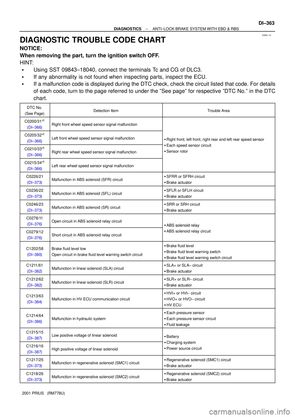
DI28U±10
± DIAGNOSTICSANTI±LOCK BRAKE SYSTEM WITH EBD & RBS
DI±363
2001 PRIUS (RM778U)
DIAGNOSTIC TROUBLE CODE CHART
NOTICE:
When removing the part, turn the ignition switch OFF.
HINT:
�Using SST 09843±18040, connect the terminals Tc and CG of DLC3.
�If any abnormality is not found when inspecting parts, inspect the ECU.
�If a malfunction code is displayed during the DTC check, check the circuit listed that code. For details
of each code, turn to the page referred to under the ºSee pageº for respective ºDTC No.º in the DTC
chart.
DTC No.
(See Page)Detection ItemTrouble Area
C0200/31*1
(DI±366)Right front wheel speed sensor signal malfunction
C0205/32*1
(DI±366)Left front wheel speed sensor signal malfunction�Right front, left front, right rear and left rear speed sensor
Eh d i itC0210/33*1
(DI±366)Right rear wheel speed sensor signal malfunction
�Each speed sensor circuit
�Sensor rotor
C0215/34*1
(DI±366)Left rear wheel speed sensor signal malfunction
C0226/21
(DI±373)Malfunction in ABS solenoid (SFR) circuit�SFRR or SFRH circuit
�Brake actuator
C0236/22
(DI±373)Malfunction in ABS solenoid (SFL) circuit�SFLR or SFLH circuit
�Brake actuator
C0246/23
(DI±373)Malfunction in ABS solenoid (SR) circuit�SRR or SRH circuit
�Brake actuator
C0278/11
(DI±376)Open circuit in ABS solenoid relay circuit�ABS solenoid relay
C0279/12
(DI±376)Short circuit in ABS solenoid relay circuit
�ABS solenoid relay
�ABS solenoid relay circuit
C1202/58
(DI±380)Brake fluid level low
Open circuit in brake fluid level warning switch circuit�Brake fluid level
�Brake fluid level warning switch
�Brake fluid level warning switch circuit
C1211/61
(DI±382)Malfunction in linear solenoid (SLA) circuit�SLA+ or SLA± circuit
�Brake actuator
C1212/62
(DI±382)Malfunction in linear solenoid (SLR) circuit�SLR+ or SLR± circuit
�Brake actuator
C1213/63
(DI±384)Malfunction in HV ECU communication circuit
�HVI+ or HVI± circuit
�HVO+ or HVO± circuit
�HV ECU
C1214/64
(DI±386)Malfunction in hydraulic system
�Each pressure sensor
�Each pressure sensor circuit
�Fluid leakage
C1215/15
(DI±387)Low positive voltage of linear solenoid�Battery
Ch i tC1216/16
(DI±387)High positive voltage of linear solenoid
�Charging system
�Power source circuit
C1217/25
(DI±373)Malfunction in regenerative solenoid (SMC1) circuit�Regenerative solenoid (SMC1) circuit
�Brake actuator
C1218/26
(DI±373)Malfunction in regenerative solenoid (SMC2) circuit�Regenerative solenoid (SMC2) circuit
�Brake actuator
Page 944 of 1943

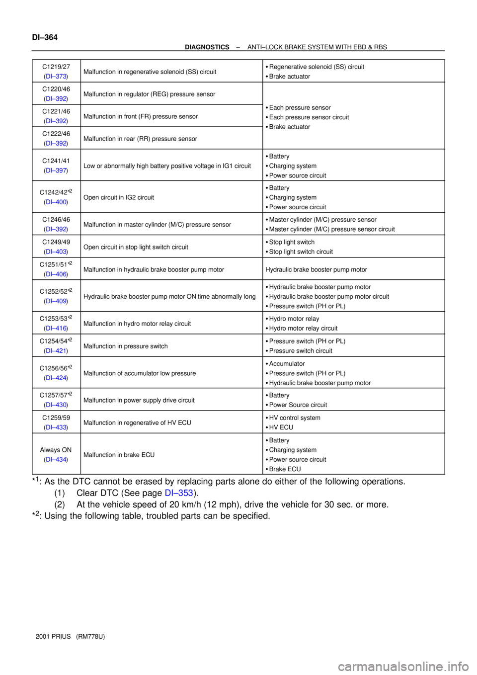
DI±364
± DIAGNOSTICSANTI±LOCK BRAKE SYSTEM WITH EBD & RBS
2001 PRIUS (RM778U)C1219/27
(DI±373)
Malfunction in regenerative solenoid (SS) circuit�Regenerative solenoid (SS) circuit
�Brake actuator
C1220/46
(DI±392)Malfunction in regulator (REG) pressure sensor
C1221/46
(DI±392)Malfunction in front (FR) pressure sensor
�Each pressure sensor
�Each pressure sensor circuit
�Brake actuatorC1222/46
(DI±392)Malfunction in rear (RR) pressure sensor
�Brake actuator
C1241/41
(DI±397)Low or abnormally high battery positive voltage in IG1 circuit
�Battery
�Charging system
�Power source circuit
C1242/42*2
(DI±400)Open circuit in IG2 circuit
�Battery
�Charging system
�Power source circuit
C1246/46
(DI±392)Malfunction in master cylinder (M/C) pressure sensor�Master cylinder (M/C) pressure sensor
�Master cylinder (M/C) pressure sensor circuit
C1249/49
(DI±403)Open circuit in stop light switch circuit�Stop light switch
�Stop light switch circuit
C1251/51*2
(DI±406)Malfunction in hydraulic brake booster pump motorHydraulic brake booster pump motor
C1252/52*2
(DI±409)Hydraulic brake booster pump motor ON time abnormally long
�Hydraulic brake booster pump motor
�Hydraulic brake booster pump motor circuit
�Pressure switch (PH or PL)
C1253/53*2
(DI±416)Malfunction in hydro motor relay circuit�Hydro motor relay
�Hydro motor relay circuit
C1254/54*2
(DI±421)Malfunction in pressure switch�Pressure switch (PH or PL)
�Pressure switch circuit
C1256/56*2
(DI±424)Malfunction of accumulator low pressure
�Accumulator
�Pressure switch (PH or PL)
�Hydraulic brake booster pump motor
C1257/57*2
(DI±430)Malfunction in power supply drive circuit�Battery
�Power Source circuit
C1259/59
(DI±433)Malfunction in regenerative of HV ECU�HV control system
�HV ECU
Always ON
(DI±434)Malfunction in brake ECU
�Battery
�Charging system
�Power source circuit
�Brake ECU
*1: As the DTC cannot be erased by replacing parts alone do either of the following operations.
(1) Clear DTC (See page DI±353).
(2) At the vehicle speed of 20 km/h (12 mph), drive the vehicle for 30 sec. or more.
*
2: Using the following table, troubled parts can be specified.
Page 957 of 1943
F12671
Brake ECU
SFRH
SFRR
SFLH
SFLR Engine Room
R/B No. 3
19
5 1121
4 W±R
2 1 4
3
7 14
IER1+
SR
8 W±B
F102
Brake Actuator 1
A
Battery10R±W
Y±B
G±W
G±O G±B
B39
32 5
12
R±Y ABS No. 1
BS
SFRR
SFLH
SFLR
SRRH
SRRR
SMC1
SS J1
J/C1
4 W
3 FL
Block
No. 1 2
1
B3 B3 B2
B3 B2 B3 B3B3B11 IA2
R±L R±G R±B SFRH
SMC2Y±B
Y±B
3
B10SRRH
SRRR
SMC1
SS SMC2 9
B10B10 B10B10 B10B10 B10B10 B10 B±L7
3
3
3
3 36
J7
J/C
W±B AA
B2 3
3Engine
Room
R/B No. 3
F131
1
B±G
1
FL
Block
No. 2ABS Solenoid Relay
R
DC/DC
MAIN
± DIAGNOSTICSANTI±LOCK BRAKE SYSTEM WITH EBD & RBS
DI±379
2001 PRIUS (RM778U)
WIRING DIAGRAM