Page 91 of 1943
2001 PRIUS (EWD414U)
A H
B FBFBFBF
2 5
105
A 5B 10
ID 2K 82D 8
B D
A EB 6B7 A H A H
4
AC
B
B
EA CCC
EA A635
A
B
A
LG LG LG LG W±L
W±L
W±L
W±L
W± B
W± L W±B W±B W±BW± L
W± L
W± LW± L
W±B
W± LLG±R
W±B
W±B W± LFROM POWER SOURCE SYSTEM (
SEE PAGE 50)
HAZARD WARNING SW H 7
CENTER CLUSTER SW C 7
LIGHT CONTROL
RHEOSTAT L 1 JUNCTION
CONNECTOR J21
JUNCTION
CONNECTOR J24
JUNCTION
CONNECTOR J11
JUNCTION
CONNECTOR J21
JUNCTION
CONNECTOR J21
RADIO AND PLAYERB R 2 A , R 3
JUNCTION
CONNECTORB J22 A , J23
JUNCTION
CONNECTORB J27 , J28A
W±LJUNCTION
CONNECTOR J21
LG LG LG
A H
A 2115A
DOME
1J 7
2G 2
2A 4
L±Y L
LG
W±L
W±L
LG
LG
LG
CE TC ILL±T
COMBINATION METERB C10 A , C11
A 14
IH 2B 62A 7
BRL
Page 94 of 1943
2001 PRIUS (EWD414U)
TURN SIGNAL AND HAZARD WARNING LIGHT
10A
TURN±HAZ FROM POWER SOURCE SYSTEM (
SEE PAGE 50)
1J 610A
GAUGE
2K 10
IA1 6
ID1 4
LH
RH
IG 4 3
A BAB
B B
2 1
2 1
IE 2K 42F32J 12
22 7 6 5C
AA
A AA A
A 133 8 1 4C
AW±B
W±B
G±Y LR E ER EL
R±LW W
R±L
G±R G±R W±B
G± B
G± B G± B W±B W±B W±BG±Y G± Y G± Y
G± YL±B
B
W± B W±BW±B
BIGHAZLL
JUNCTION
CONNECTOR J20
HAZARD SW
[HAZARD WARNING SW] H 7
TURN SIGNAL FLASHER RELAY T 5
IA1 11
G±Y
TURN SIGNAL SW
[COMB. SW] C13
JUNCTION
CONNECTOR J17
JUNCTION
CONNECTOR J 1
JUNCTION
CONNECTOR J 7
FRONT TURN SI GNAL LI GHT RH F 8
FRONT TURN SI GNAL LI GHT LH F 7 JUNCTION
CONNECTOR J18
JUNCTION CONNECTORB J12 A , J13A
AJUNCTION
CONNECTOR J 4
Page 96 of 1943

2001 PRIUS (EWD414U)
TURN SIGNAL AND HAZARD WARNING LIGHT
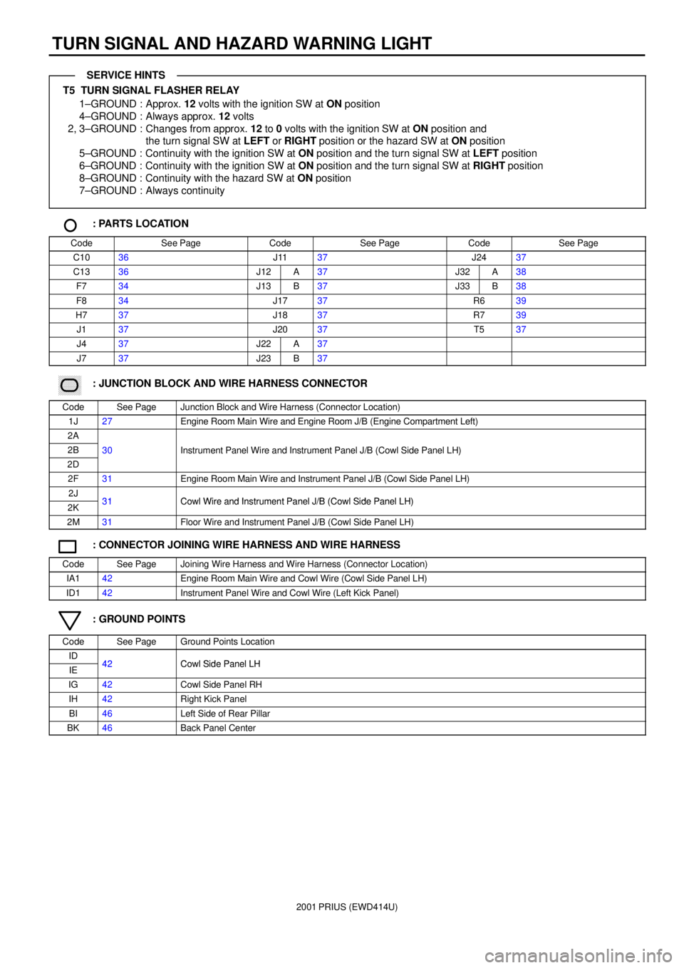
T5 TURN SIGNAL FLASHER RELAY
1±GROUND : Approx. 12 volts with the ignition SW at ON position
4±GROUND : Always approx. 12 volts
2, 3±GROUND : Changes from approx. 12 to 0 volts with the ignition SW at ON position and
the turn signal SW at LEFT or RIGHT position or the hazard SW at ON position
5±GROUND : Continuity with the ignition SW at ON position and the turn signal SW at LEFT position
6±GROUND : Continuity with the ignition SW at ON position and the turn signal SW at RIGHT position
8±GROUND : Continuity with the hazard SW at ON position
7±GROUND : Always continuity
: PARTS LOCATION
CodeSee PageCodeSee PageCodeSee Page
C1036J1137J2437
C1336J12A37J32A38
F734J13B37J33B38
F834J1737R639
H737J1837R739
J137J2037T537
J437J22A37
J737J23B37
������ ���: JUNCTION BLOCK AND WIRE HARNESS CONNECTOR
CodeSee PageJunction Block and Wire Harness (Connector Location)
1J27Engine Room Main Wire and Engine Room J/B (Engine Compartment Left)
2A
2B30Instrument Panel Wire and Instrument Panel J/B (Cowl Side Panel LH)
2D
()
2F31Engine Room Main Wire and Instrument Panel J/B (Cowl Side Panel LH)
2J31Cowl Wire and Instrument Panel J/B (Cowl Side Panel LH)2K31Cowl Wire and Instrument Panel J/B (Cowl Side Panel LH)
2M31Floor Wire and Instrument Panel J/B (Cowl Side Panel LH)
: CONNECTOR JOINING WIRE HARNESS AND WIRE HARNESS
CodeSee PageJoining Wire Harness and Wire Harness (Connector Location)
IA142Engine Room Main Wire and Cowl Wire (Cowl Side Panel LH)
ID142Instrument Panel Wire and Cowl Wire (Left Kick Panel)
: GROUND POINTS
CodeSee PageGround Points Location
ID42Cowl Side Panel LHIE42Cowl Side Panel LH
IG42Cowl Side Panel RH
IH42Right Kick Panel
BI46Left Side of Rear Pillar
BK46Back Panel Center
SERVICE HINTS
Page 102 of 1943

2001 PRIUS (EWD414U)
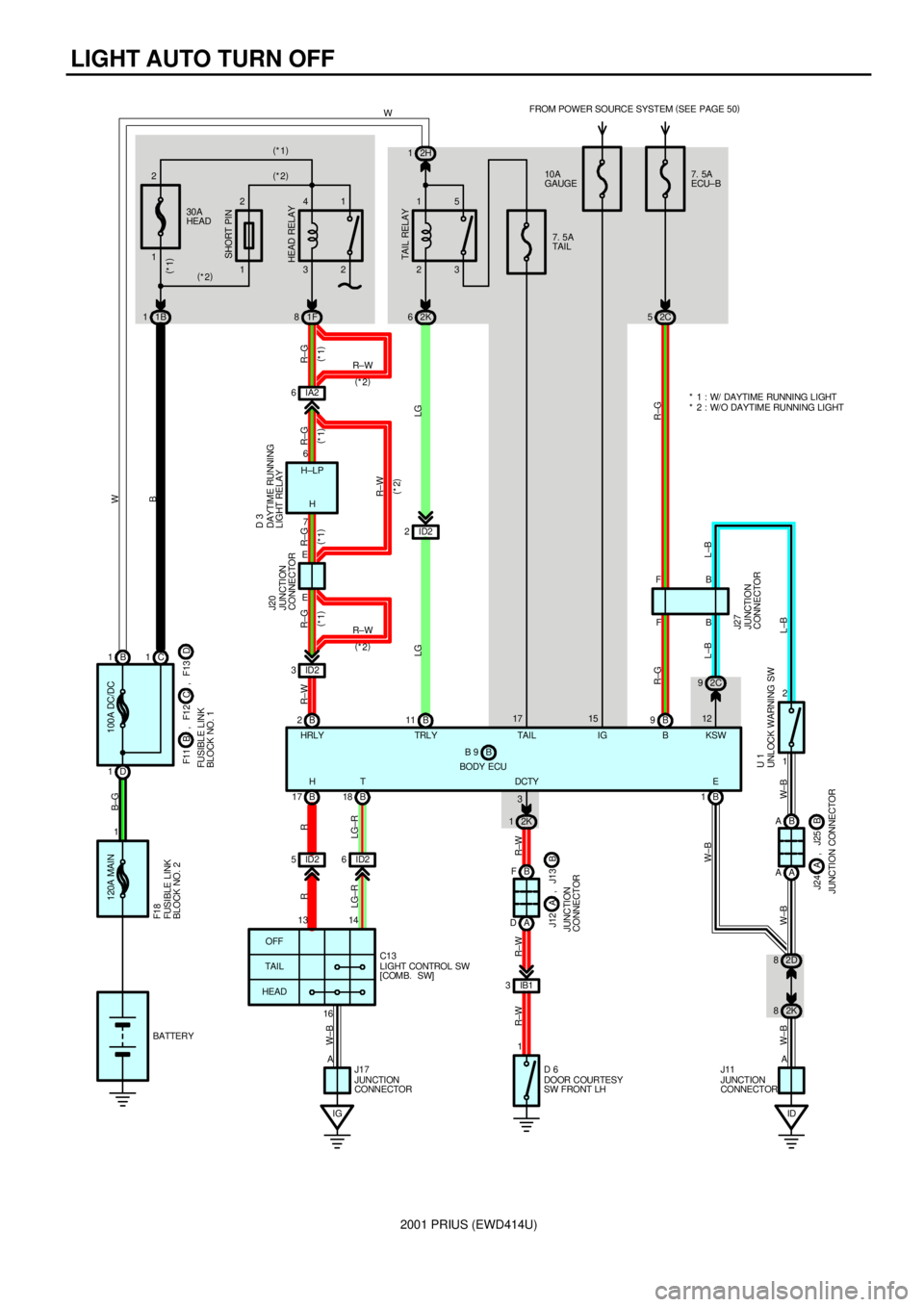
LIGHT AUTO TURN OFF
120A MAIN
1B 1C1
D 11B 1130A
HEAD
1 2
32 41
1F 823 15
7. 5A
TAI L FROM POWER SOURCE SYSTEM (
SEE PAGE 50)
2K 62H 1
B 2B11ID2 2 IA2 6
ID2 3
B 17 B18
IG ID2 5ID262K 1
B F
A D
IB1 3
1
ID 2C 9
B 11 2
B A
A A
2D 8
2K 8 B
16 7
EB 6
E
13 14
AA 17 R±W R±WW
B W B±G
LG LGR±G R±G R±G R±G R±W R
LG±R R
LG±R W±B
R±W R±W R±W
W±B
W± B W±B W±BL±B L±B
L±B
2
(
*1) (
*1) (
*1)
R±W
(
*2)
(
*2)
(
*2) (
*1)H H±LP
TAI L REL AY HEAD RELAYSHORT PIN
JUNCTION
CONNECTOR J20DAYTIME RUNNING
LIGHT RELAY D 3
JUNCTION
CONNECTOR J27
UNLOCK WARNING SW U 1
OFF
TAI L
HEAD
100A DC/DC
FUSIBLE LINK
BLOCK NO. 2 F1 8
FUSIBLE LINK
BLOCK NO. 1C F11 B , F1 2
JUNCTION
CONNECTORB J12 A , J13
JUNCTION CONNECTORB J24 A , J25
DOOR COURTESY
SW FRONT LH D 6
JUNCTION
CONNECTOR J17LIGHT CONTROL SW
[COMB. SW] C13
JUNCTION
CONNECTOR J11
D , F13
BATTERY12
3* 1 : W/ DAYTIME RUNNING LIGHT
* 2 : W/O DAYTIME RUNNING LIGHT (
*1)
(
*2)
(
*2)
(
*1)
7. 5A
ECU±B
2C 5
F
F
B 9
BODY ECUB 9 B
R±G R±G
10A
GAUGE
15
H T DCTY E HRLY TRLY TAIL IG B KSW
Page 113 of 1943
2001 PRIUS (EWD414U)
ID 2C 9
B 11 2
B A
A A
2D 8
2K 8 B B
A E
W±B
W± B W±B W±BL±B L±B
L±BJUNCTION
CONNECTOR J27
UNLOCK WARNING SW U 1
JUNCTION CONNECTORB J24 A , J25
JUNCTION
CONNECTOR J11 12* 1 : W/ DAYTIME RUNNING LIGHT
* 2 : W/O DAYTIME RUNNING LIGHT
BODY ECUB B 8 , B 9A L
A 16
MPX±A 15
MPX+
GR
MPX2 MPX1 14
13
GR±L
MPD2 MPD14
11
B 2
BUZZERB 3A22 A21
GR
L
L GR ±B
MPX+MP2+4
1115A
DOME FROM POWER SOURCE SYSTEM (
SEE PAGE 50)
1J 7
2G 2
2A 4
L±Y GR ±B GR ±B
GR± B
ENGINE CONTROL
MODULE E10
GATEWAY ECU G 1
A/C AMPLIFIER A 7
COMBINATION METERB C10 , C11A
2A 7
2B 6A 14
IH
L BR
KSW
Page 117 of 1943

2001 PRIUS (EWD414U)
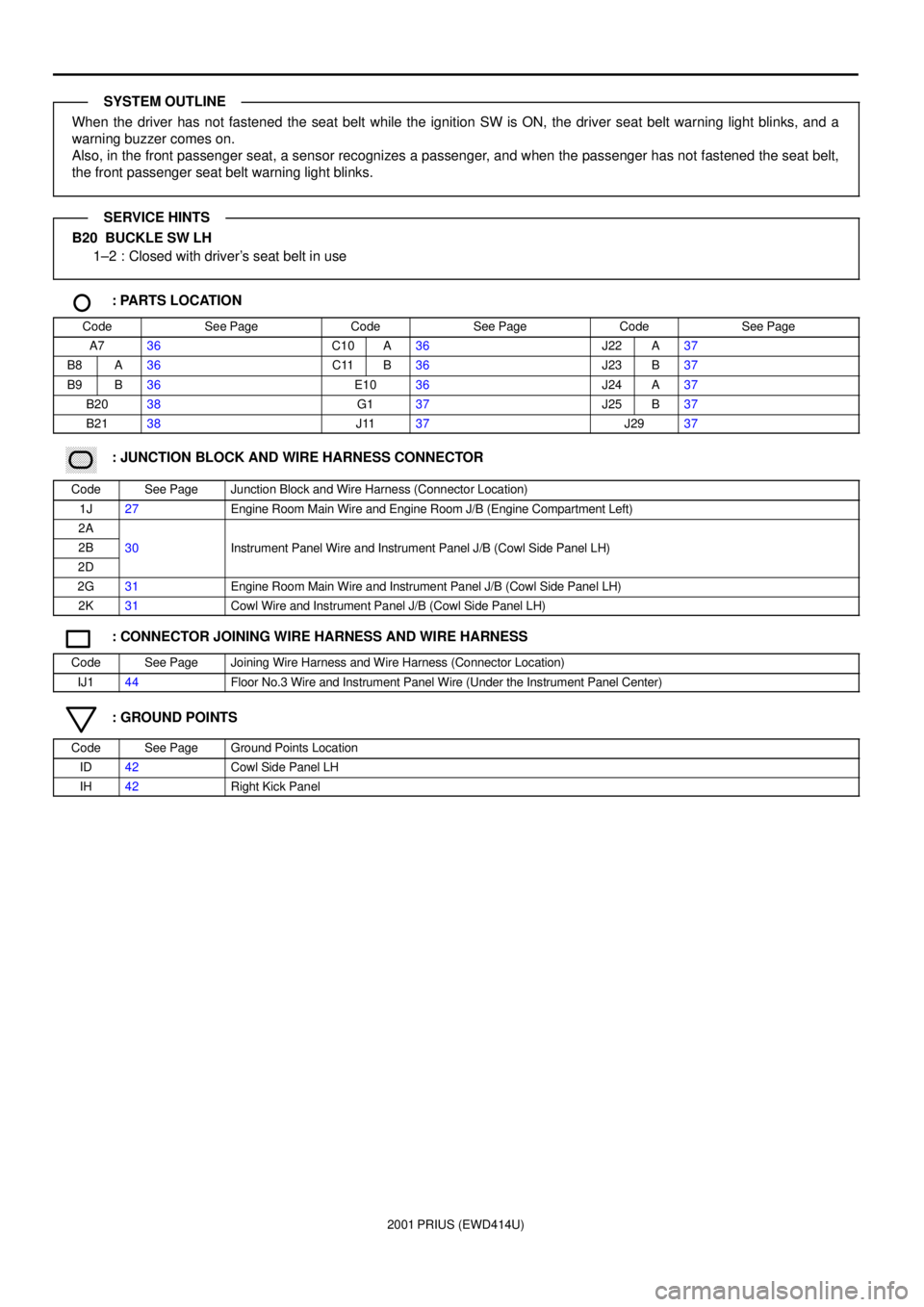
When the driver has not fastened the seat belt while the ignition SW is ON, the driver seat belt warning light blinks, and a
warning buzzer comes on.
Also, in the front passenger seat, a sensor recognizes a passenger, and when the passenger has not fastened the seat belt,
the front passenger seat belt warning light blinks.
B20 BUCKLE SW LH
1±2 : Closed with driver's seat belt in use
: PARTS LOCATION
CodeSee PageCodeSee PageCodeSee Page
A736C10A36J22A37
B8A36C11B36J23B37
B9B36E1036J24A37
B2038G137J25B37
B2138J1137J2937
������ ���: JUNCTION BLOCK AND WIRE HARNESS CONNECTOR
CodeSee PageJunction Block and Wire Harness (Connector Location)
1J27Engine Room Main Wire and Engine Room J/B (Engine Compartment Left)
2A
2B30Instrument Panel Wire and Instrument Panel J/B (Cowl Side Panel LH)
2D
()
2G31Engine Room Main Wire and Instrument Panel J/B (Cowl Side Panel LH)
2K31Cowl Wire and Instrument Panel J/B (Cowl Side Panel LH)
: CONNECTOR JOINING WIRE HARNESS AND WIRE HARNESS
CodeSee PageJoining Wire Harness and Wire Harness (Connector Location)
IJ144Floor No.3 Wire and Instrument Panel Wire (Under the Instrument Panel Center)
: GROUND POINTS
CodeSee PageGround Points Location
ID42Cowl Side Panel LH
IH42Right Kick Panel
SYSTEM OUTLINE
SERVICE HINTS
Page 130 of 1943
2001 PRIUS (EWD414U)
SHIFT LOCK
15A
STOP
2K 95A
ECU±IG
2I 2 10A
ACC FROM POWER SOURCE SYSTEM (
SEE PAGE 50)
2D 2
2 1
A E
B D
ID2 1
3 4
E E
B D
A E A AAAB A
2D 8
2K 8
ID AB B
D DID1 5 A C
B CA D
A D
4 JUNCTION
CONNECTOR J26
JUNCTION
CONNE CTOR J21 STOP
LIGHT
SW S 3
KEY INTERLOCK
SOLENOID
[UNLOCK
WARNING SW] U 1
JUNCTION
CONNECTOR J21
JUNCTION
CONNECTOR J11613
5
R±B G±W G± W G±W
GR±R
B±Y B±YGR±R GR±R
B±Y B±Y L W± B
W±B W±BW±B W±B W±B
SHIFT LOCK ECU S 2 STP ACC IG
W± BKLS+ E JUNCTION
CONNECTORB J14 , J15AJUNCTION
CONNECTORB J27 , J28AJUNCTION
CONNE CTORJ14 A
JUNCTION
CONNECTORB J22 , J23A JUNCTION
CONNECTORB J24 , J25ASHIFT LOCK CONTROL SW
SHIFT LOCK SOLENOID P1
P
P2
SLS+
SLS±3
2
1
12 R
B
Y
L±R
BLOCK
FREE
Page 142 of 1943

2001 PRIUS (EWD414U)
WIRELESS DOOR LOCK CONTROL
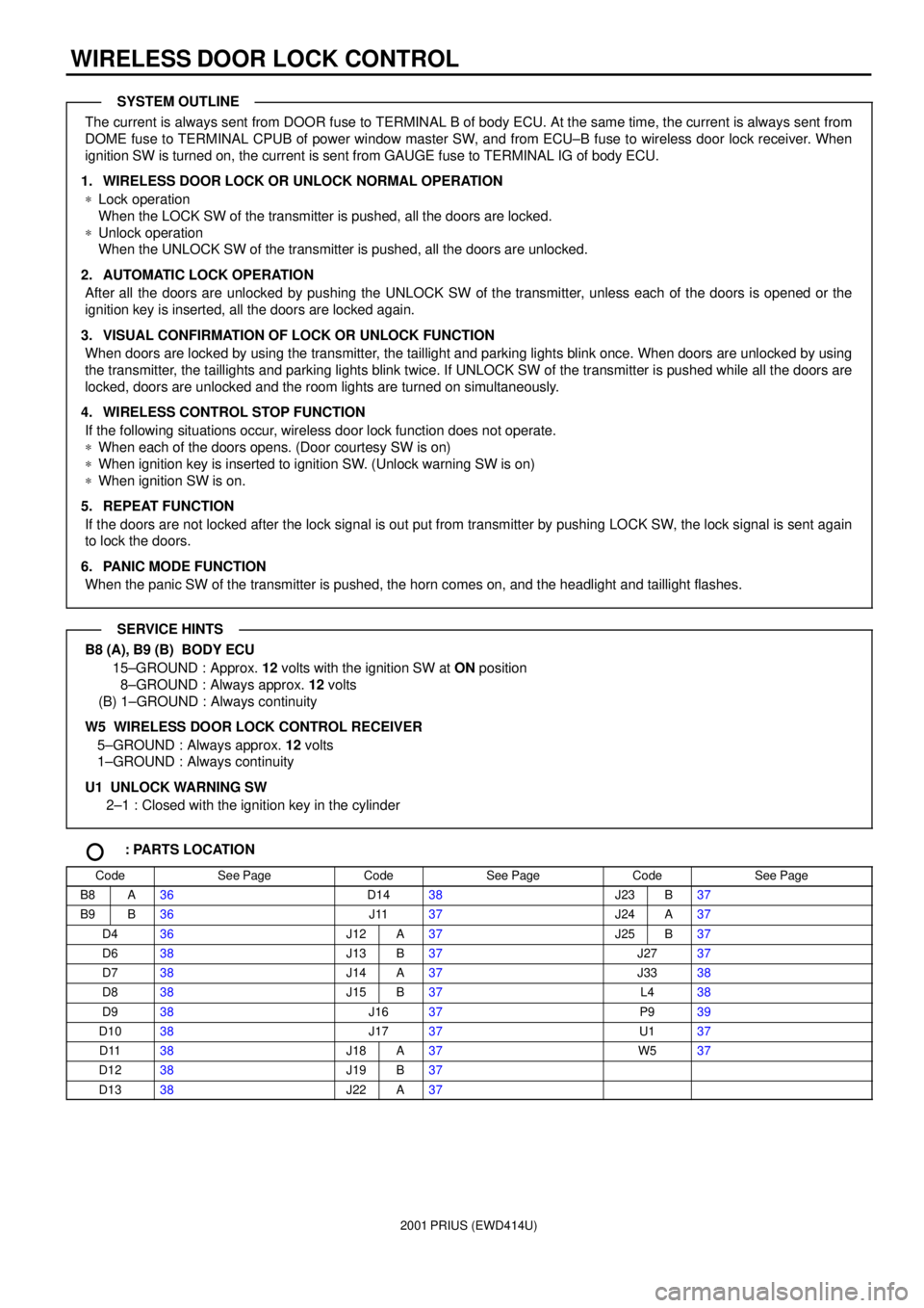
The current is always sent from DOOR fuse to TERMINAL B of body ECU. At the same time, the current is always sent from
DOME fuse to TERMINAL CPUB of power window master SW, and from ECU±B fuse to wireless door lock receiver. When
ignition SW is turned on, the current is sent from GAUGE fuse to TERMINAL IG of body ECU.
1. WIRELESS DOOR LOCK OR UNLOCK NORMAL OPERATION
*Lock operation
When the LOCK SW of the transmitter is pushed, all the doors are locked.
*Unlock operation
When the UNLOCK SW of the transmitter is pushed, all the doors are unlocked.
2. AUTOMATIC LOCK OPERATION
After all the doors are unlocked by pushing the UNLOCK SW of the transmitter, unless each of the doors is opened or the
ignition key is inserted, all the doors are locked again.
3. VISUAL CONFIRMATION OF LOCK OR UNLOCK FUNCTION
When doors are locked by using the transmitter, the taillight and parking lights blink once. When doors are unlocked by using
the transmitter, the taillights and parking lights blink twice. If UNLOCK SW of the transmitter is pushed while all the doors are
locked, doors are unlocked and the room lights are turned on simultaneously.
4. WIRELESS CONTROL STOP FUNCTION
If the following situations occur, wireless door lock function does not operate.
*When each of the doors opens. (Door courtesy SW is on)
*When ignition key is inserted to ignition SW. (Unlock warning SW is on)
*When ignition SW is on.
5. REPEAT FUNCTION
If the doors are not locked after the lock signal is out put from transmitter by pushing LOCK SW, the lock signal is sent again
to lock the doors.
6. PANIC MODE FUNCTION
When the panic SW of the transmitter is pushed, the horn comes on, and the headlight and taillight flashes.
B8 (A), B9 (B) BODY ECU
15±GROUND : Approx. 12 volts with the ignition SW at ON position
8±GROUND : Always approx. 12 volts
(B) 1±GROUND : Always continuity
W5 WIRELESS DOOR LOCK CONTROL RECEIVER
5±GROUND : Always approx. 12 volts
1±GROUND : Always continuity
U1 UNLOCK WARNING SW
2±1 : Closed with the ignition key in the cylinder
: PARTS LOCATION
CodeSee PageCodeSee PageCodeSee Page
B8A36D1438J23B37
B9B36J1137J24A37
D436J12A37J25B37
D638J13B37J2737
D738J14A37J3338
D838J15B37L438
D938J1637P939
D1038J1737U137
D1138J18A37W537
D1238J19B37
D1338J22A37
SYSTEM OUTLINE
SERVICE HINTS