Page 1789 of 1943

I17865
Fuel Sender Gauge Connector
I17865
Fuel Sender Gauge Connector
I01277
BatteryWarning Light Ignition
Switch
Wire Harness Side
1
I01278
BE±44
± BODY ELECTRICALCOMBINATION METER
2001 PRIUS (RM778U)
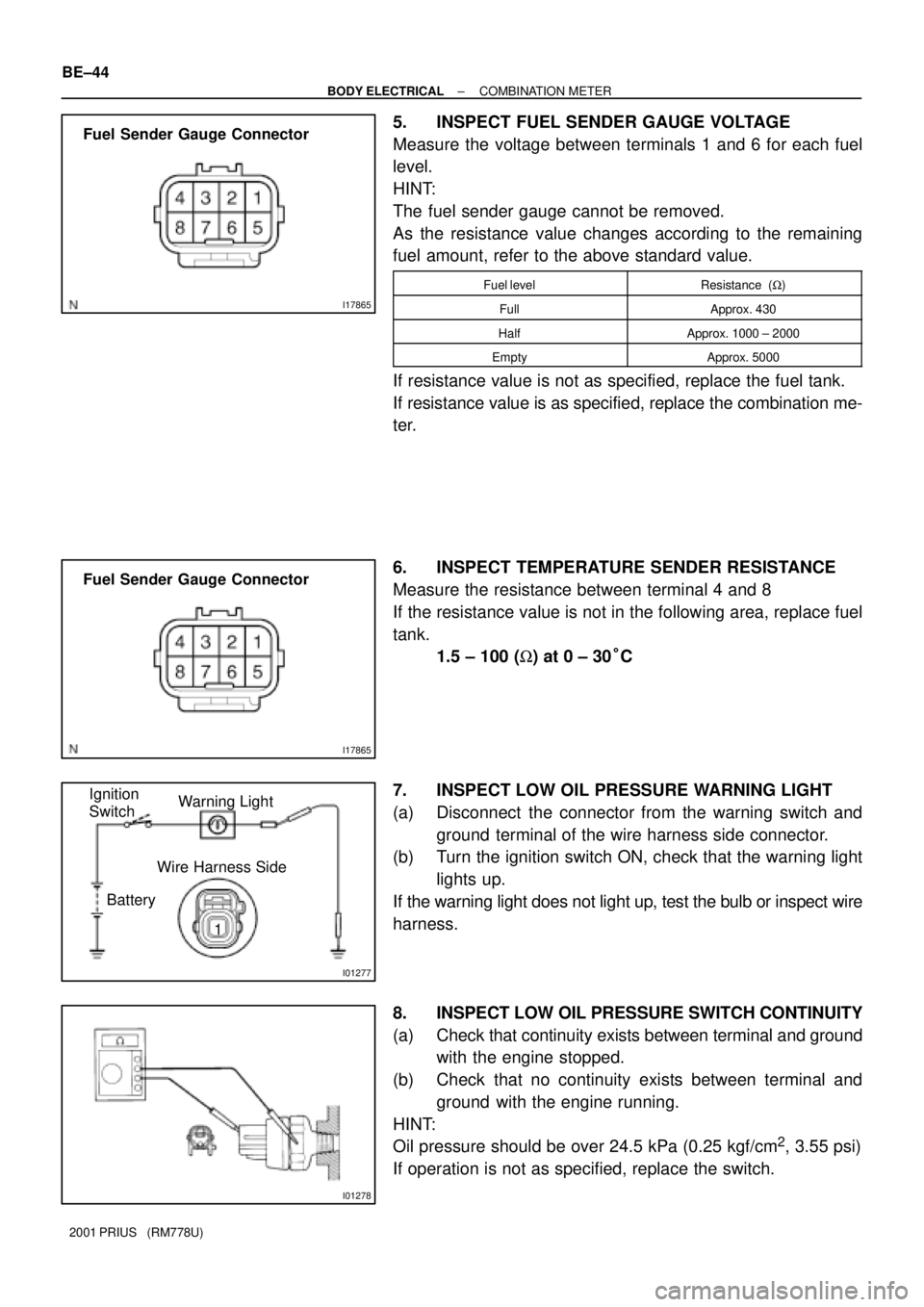
5. INSPECT FUEL SENDER GAUGE VOLTAGE
Measure the voltage between terminals 1 and 6 for each fuel
level.
HINT:
The fuel sender gauge cannot be removed.
As the resistance value changes according to the remaining
fuel amount, refer to the above standard value.
Fuel levelResistance (W)
FullApprox. 430
HalfApprox. 1000 ± 2000
EmptyApprox. 5000
If resistance value is not as specified, replace the fuel tank.
If resistance value is as specified, replace the combination me-
ter.
6. INSPECT TEMPERATURE SENDER RESISTANCE
Measure the resistance between terminal 4 and 8
If the resistance value is not in the following area, replace fuel
tank.
1.5 ± 100 (W) at 0 ± 30°C
7. INSPECT LOW OIL PRESSURE WARNING LIGHT
(a) Disconnect the connector from the warning switch and
ground terminal of the wire harness side connector.
(b) Turn the ignition switch ON, check that the warning light
lights up.
If the warning light does not light up, test the bulb or inspect wire
harness.
8. INSPECT LOW OIL PRESSURE SWITCH CONTINUITY
(a) Check that continuity exists between terminal and ground
with the engine stopped.
(b) Check that no continuity exists between terminal and
ground with the engine running.
HINT:
Oil pressure should be over 24.5 kPa (0.25 kgf/cm
2, 3.55 psi)
If operation is not as specified, replace the switch.
Page 1790 of 1943

BE1217
BatteryWarning Light
Ignition
Switch
I11650
BE0044
BatteryWarning Light
Ignition
Switch
Z11183
± BODY ELECTRICALCOMBINATION METER
BE±45
2001 PRIUS (RM778U)
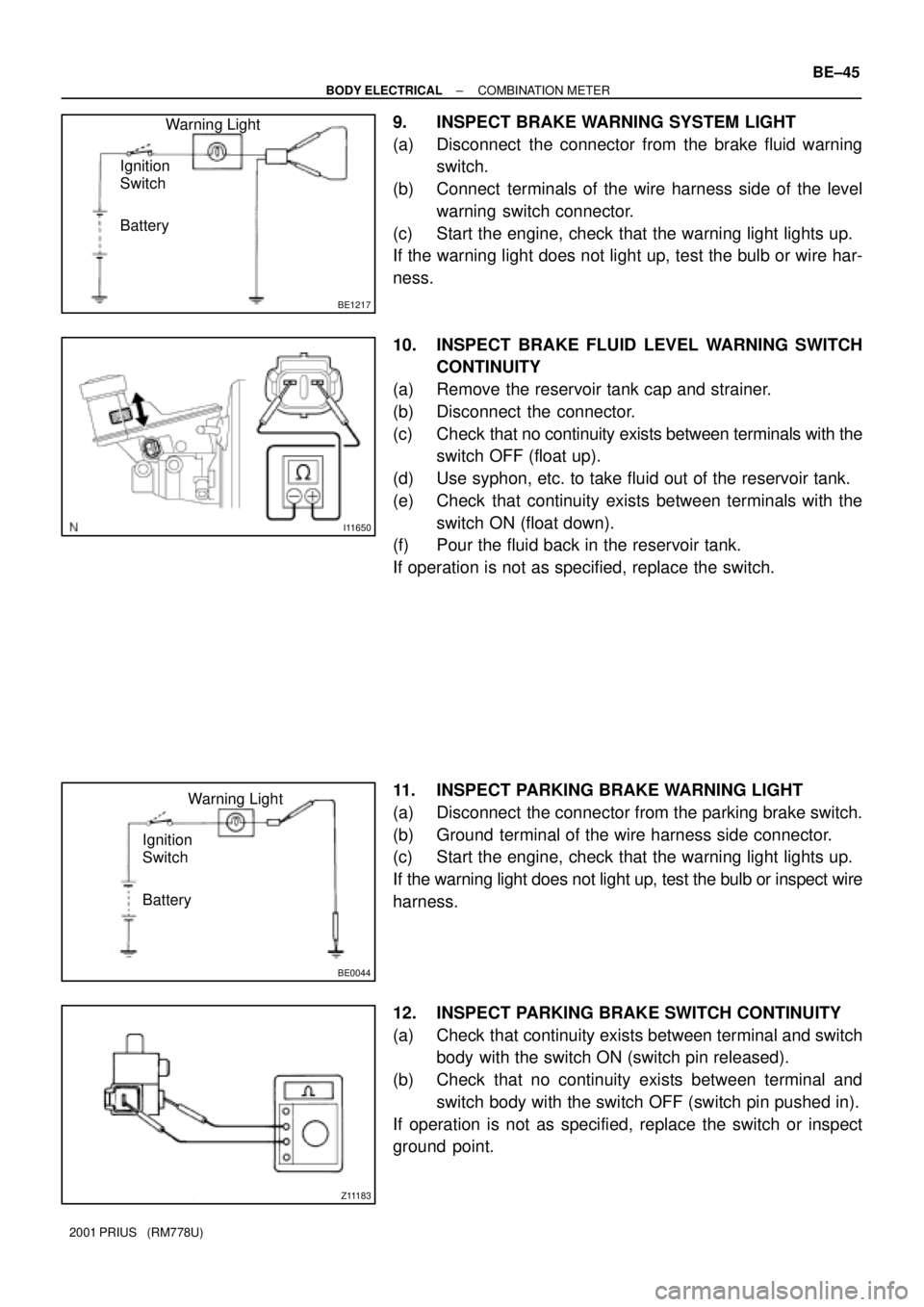
9. INSPECT BRAKE WARNING SYSTEM LIGHT
(a) Disconnect the connector from the brake fluid warning
switch.
(b) Connect terminals of the wire harness side of the level
warning switch connector.
(c) Start the engine, check that the warning light lights up.
If the warning light does not light up, test the bulb or wire har-
ness.
10. INSPECT BRAKE FLUID LEVEL WARNING SWITCH
CONTINUITY
(a) Remove the reservoir tank cap and strainer.
(b) Disconnect the connector.
(c) Check that no continuity exists between terminals with the
switch OFF (float up).
(d) Use syphon, etc. to take fluid out of the reservoir tank.
(e) Check that continuity exists between terminals with the
switch ON (float down).
(f) Pour the fluid back in the reservoir tank.
If operation is not as specified, replace the switch.
11. INSPECT PARKING BRAKE WARNING LIGHT
(a) Disconnect the connector from the parking brake switch.
(b) Ground terminal of the wire harness side connector.
(c) Start the engine, check that the warning light lights up.
If the warning light does not light up, test the bulb or inspect wire
harness.
12. INSPECT PARKING BRAKE SWITCH CONTINUITY
(a) Check that continuity exists between terminal and switch
body with the switch ON (switch pin released).
(b) Check that no continuity exists between terminal and
switch body with the switch OFF (switch pin pushed in).
If operation is not as specified, replace the switch or inspect
ground point.
Page 1791 of 1943
BE0044
BatteryWarning Light
Ignition
Switch BE±46
± BODY ELECTRICALCOMBINATION METER
2001 PRIUS (RM778U)
13. INSPECT OPEN DOOR WARNING LIGHT
Disconnect the connector from the door courtesy switch, and
ground terminal 1 of the wire harness side connector and check
that the warning light lights up.
If the warning light does not light up, inspect the bulb or wire har-
ness.
Page 1815 of 1943

BE0IM±13
Make the vehicle in the initialized condition:
The initialized condition is the condition when the following conditions are satisfied.
(1) Key plate has not been inserted in the ignition key cylinder.
(2) All the doors are closed. (Door warning light is off.)
(3) All the doors are locked.
Under the standard operation, when repeating the operation of UNLOCK and LOCK switch
3 times or more alternately, check the UNLOCK±LOCK operation from 3rd time onward.
� Following procedures are standard operation.
(1) Keep about 1 M away to the right direction from the outside handle of a driver's seat.
(2) Face the transmitter toward the vehicle and press one of transmitter switches for about 1 sec.
Normal
� Operative distance may differ according to
an operator, the way of holding the transmitter
or position.
� Because weak electric wave is used, when
there is strong wave or noise in the used
frequency ,operation distance might be
shortened.
NoYe s
Only wireless function (Remote control) will not operate.
(If a new transmitter or a transmitter of the same type that works properly with the vehicle is not available.)
Basic function check: BE±78
± BODY ELECTRICALWIRELESS DOOR LOCK CONTROL SYSTEM
2001 PRIUS (RM778U)
PRE±CHECK