Page 721 of 1943

A09060
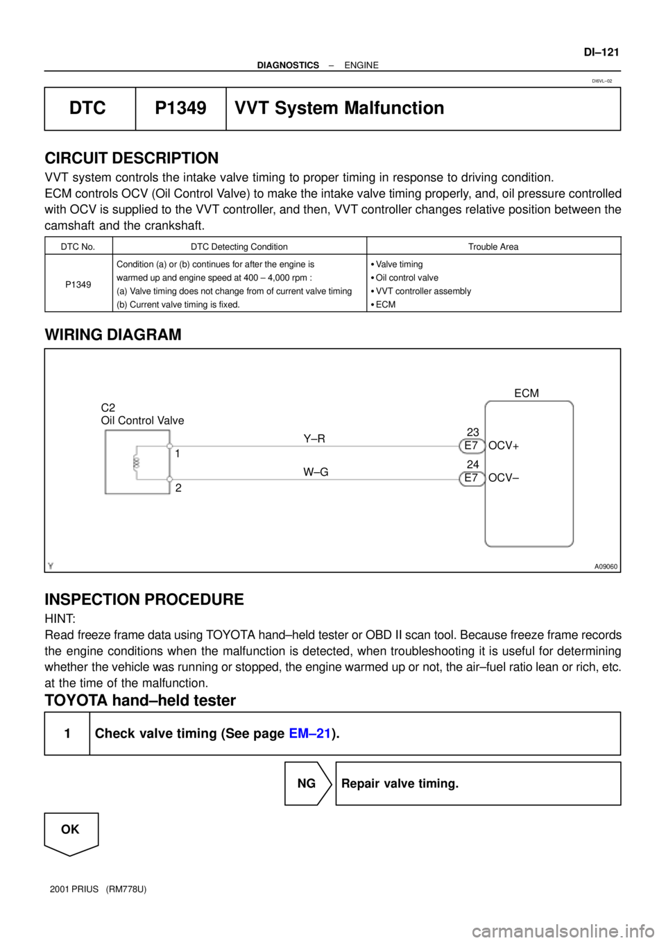
C2
Oil Control Valve
2 1Y±R
W±GECM
OCV+
OCV± 23
24
E7 E7
± DIAGNOSTICSENGINE
DI±121
2001 PRIUS (RM778U)
DTC P1349 VVT System Malfunction
CIRCUIT DESCRIPTION
VVT system controls the intake valve timing to proper timing in response to driving condition.
ECM controls OCV (Oil Control Valve) to make the intake valve timing properly, and, oil pressure controlled
with OCV is supplied to the VVT controller, and then, VVT controller changes relative position between the
camshaft and the crankshaft.
DTC No.DTC Detecting ConditionTrouble Area
P1349
Condition (a) or (b) continues for after the engine is
warmed up and engine speed at 400 ± 4,000 rpm :
(a) Valve timing does not change from of current valve timing
(b) Current valve timing is fixed.�Valve timing
�Oil control valve
�VVT controller assembly
�ECM
WIRING DIAGRAM
INSPECTION PROCEDURE
HINT:
Read freeze frame data using TOYOTA hand±held tester or OBD II scan tool. Because freeze frame records
the engine conditions when the malfunction is detected, when troubleshooting it is useful for determining
whether the vehicle was running or stopped, the engine warmed up or not, the air±fuel ratio lean or rich, etc.
at the time of the malfunction.
TOYOTA hand±held tester
1 Check valve timing (See page EM±21).
NG Repair valve timing.
OK
DI6VL±02
Page 727 of 1943

A14056
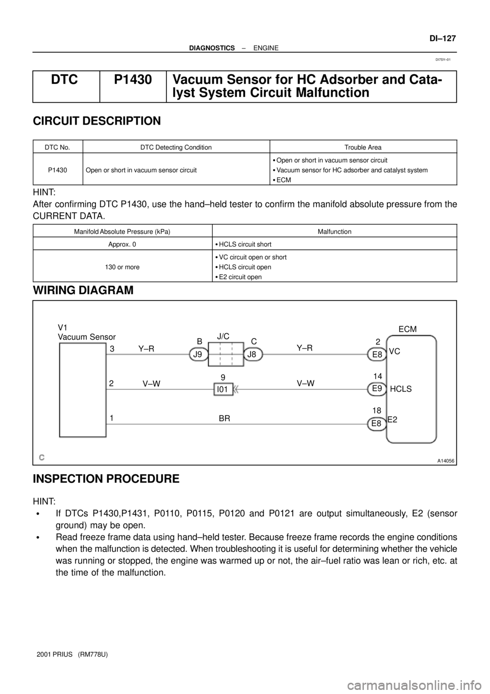
V1
Vacuum SensorECM
3
BR 2
1V±W Y±R
E9
E82
14
18VC
HCLS
E2 E8 Y±RJ/C
C
J8 B
J9
V±W9
I01
± DIAGNOSTICSENGINE
DI±127
2001 PRIUS (RM778U)
DTC P1430 Vacuum Sensor for HC Adsorber and Cata-
lyst System Circuit Malfunction
CIRCUIT DESCRIPTION
DTC No.DTC Detecting ConditionTrouble Area
P1430Open or short in vacuum sensor circuit
�Open or short in vacuum sensor circuit
�Vacuum sensor for HC adsorber and catalyst system
�ECM
HINT:
After confirming DTC P1430, use the hand±held tester to confirm the manifold absolute pressure from the
CURRENT DATA.
Manifold Absolute Pressure (kPa)Malfunction
Approx. 0�HCLS circuit short
130 or more
�VC circuit open or short
�HCLS circuit open
�E2 circuit open
WIRING DIAGRAM
INSPECTION PROCEDURE
HINT:
�If DTCs P1430,P1431, P0110, P0115, P0120 and P0121 are output simultaneously, E2 (sensor
ground) may be open.
�Read freeze frame data using hand±held tester. Because freeze frame records the engine conditions
when the malfunction is detected. When troubleshooting it is useful for determining whether the vehicle
was running or stopped, the engine was warmed up or not, the air±fuel ratio was lean or rich, etc. at
the time of the malfunction.
DI7SY±01
Page 731 of 1943

± DIAGNOSTICSENGINE
DI±131
2001 PRIUS (RM778U)
DTC P1431Vacuum Sensor for HC Adsorber and Catalyst Sys-
tem Circuit Range/Performance Problem
CIRCUIT DESCRIPTION
Refer to DTC P1430 on page DI±127.
DTC No.DTC Detecting ConditionTrouble Area
P1431
Conditions (a), (b), (c) and (d) continue with more than 10
seconds: (2 trip detection logic)
(b) PIM > 3.96 V
(c) VSV for HC Adsorber and Catalyst System is ON
(d) Engine speed is 1,000 rpm or more
(e) THW � 0°C (32°F)
�Vacuum sensor for HC adsorber and catalyst systemP1431Conditions (a), (b) and (c) continue with more than 10 se-
cond: (2 trip detection logic)
(a) PIM < 1.2 V
(b) Engine stopped
(c) VSV for HC Adsorber and Catalyst System is OFF
(d) THW � 0°C (32°F)
�Vacuum sensor for HC adsorber and catalyst system
�Vacuum line
INSPECTION PROCEDURE
HINT:
�If DTCs P1430, P1431, P0110, P0115, P0116, P0120, P0121 are output simultaneously, E2 (sensor
ground) may be open.
�Read freeze frame data using hand±held tester. Because freeze frame records the engine conditions
when the malfunction is detected. When troubleshooting it is useful for determining whether the vehicle
was running or stopped, the engine was warmed up or not, the air±fuel ratio was lean or rich, etc. at
the time of the malfunction.
�When a bypass valve has a trouble, it is possible that DTC P1341 will be detected ahead of DTC
P1436, and P1437, so in case that P1431 even if they are not memorized.
1 Are there any other codes (besides DTC P1431) being output?
YES Go to relevant DTC chart.
NO
DI7SZ±01
Page 733 of 1943

± DIAGNOSTICSENGINE
DI±133
2001 PRIUS (RM778U)
DTC P1436 Bypass Valve Malfunction
CIRCUIT DESCRIPTION
Before the engine is started, the bypass valve remains open. When the engine is cold started, the ECM out-
puts a signal to the VSV (for HC adsorber and catalyst system), which open the passage between the intake
manifold and the actuator, thus applying a vacuum to the actuator. As a result, the bypass valve closes.
Immediately after the engine has started, the exhaust gases pass through the adsorber material in with HC
becomes adsorbed and stored for a certain length of time (until the temperature of the front TWC rises).
Thus, the release of HC into the atmosphere is prevented when the temperature of the TWC is low.
After the TWC has warmed up, the VSV closes the passage between the intake manifold and the actuator,
causing the bypass valve to open. Then, as the temperature of the rear TWC rises, the temperature of the
adsorber material that surrounds it also rises, and the HC starts to desorb, and becomes cleaned by the
TWC.
Furthermore, this system activates the VSV when decelerating and the HC adsorber has become the speci-
fied temperature, allowing the vacuum from the intake manifold to close the bypass valve in order to scav-
enge the HC that remains in the adsorber material.
DTC No.DTC Detecting ConditionTrouble Area
P1436
With cold start when the water temperature and intake air
temperature were ±10 °C (14 °F)to 40 °C (104 °F), and
when the water temperature has reached 45 °C (113 °F) or
more and the engine load factor has become more than 30
%, the valve operation is not preformed normally.
�Vacuum line
�Actuator
�Front exhaust pipe
INSPECTION PROCEDURE
1 Check vacuum hose and tube between VSV and actuator for HC adsorber and
catalyst system.
CHECK:
Check that the vacuum hose and tube for clog and deformation.
NG Repair or replace.
OK
2 Check actuator operation (See page EC±13).
OK Recheck after assembly.
NG
DI7T0±01
Page 735 of 1943

± DIAGNOSTICSENGINE
DI±135
2001 PRIUS (RM778U)
DTC P1437 Vacuum Line Malfunction
CIRCUIT DESCRIPTION
Refer to DTC P1436 on page DI±133.
DTC No.DTC Detecting ConditionTrouble Area
P1437
With cold start when the water temperature and intake air
temperature were ± 10 °C (14 °F) to 40 °C (104 °F), and
when the water temperature has reached 45 °C (113 °F) or
more and the engine load factor has become more than 30
%, the negative pressure has abnormality.�Vacuum line
�VSV for HC adsober and catalyst system
�Vacuum sensor for HC adsober and catalyst system
�Check valve
INSPECTION PROCEDURE
TOYOTA hand±held tester:
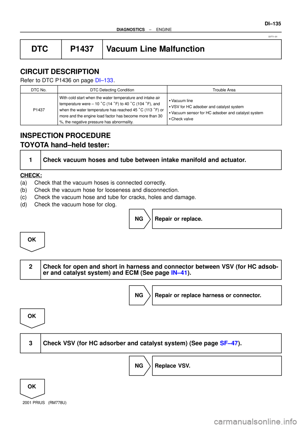
1 Check vacuum hoses and tube between intake manifold and actuator.
CHECK:
(a) Check that the vacuum hoses is connected correctly.
(b) Check the vacuum hose for looseness and disconnection.
(c) Check the vacuum hose and tube for cracks, holes and damage.
(d) Check the vacuum hose for clog.
NG Repair or replace.
OK
2 Check for open and short in harness and connector between VSV (for HC adsob-
er and catalyst system) and ECM (See page IN±41).
NG Repair or replace harness or connector.
OK
3 Check VSV (for HC adsorber and catalyst system) (See page SF±47).
NG Replace VSV.
OK
DI7T1±01
Page 742 of 1943
A14034
Battery
MAIN
FL Block No. 1
F131
B±GEngine Room J/B
1B43
E8BATT ECM
12
1A F12R±W EFI
FL Block No. 2B
1
± DIAGNOSTICSENGINE
DI±143
2001 PRIUS (RM778U)
DTC P1600 ECM BATT Malfunction
CIRCUIT DESCRIPTION
Battery positive voltage is supplied to terminal BATT of the ECM even when the ignition switch is OFF for
use by the DTC memory and air±fuel ratio adaptive control value memory, etc.
DTC No.DTC Detecting ConditionTrouble Area
P1600Open in back up power source circuit�Open in back up power source circuit
�ECM
HINT:
If DTC P1600 appear, the ECM does not store another DTC.
WIRING DIAGRAM
INSPECTION PROCEDURE
HINT:
Read freeze frame data using TOYOTA hand±held tester or OBD II scan tool. Because freeze frame records
the engine conditions when the malfunction is detected, when troubleshooting it is useful for determining
whether the vehicle was running or stopped, the engine warmed up or not, the air±fuel ratio lean or rich, etc.
at the time of the malfunction.
DI6VN±02
Page 748 of 1943

DI±150
± DIAGNOSTICSENGINE
2001 PRIUS (RM778U)
DTC P1656 OCV Circuit Malfunction
CIRCUIT DESCRIPTION
Refer to DTC P1349 on page DI±121.
DTC No.DTC Detecting ConditionTrouble Area
P1656
P1663Open or short in oil control valve circuit
�Open or short in oil control valve circuit
�Oil control valve
�ECM
WIRING DIAGRAM
Refer to DTC P1349 on page DI±121.
INSPECTION PROCEDURE
HINT:
Read freeze frame data using TOYOTA hand±held tester or OBD II scan tool. Because freeze frame records
the engine conditions when the malfunction is detected, when troubleshooting it is useful for determining
whether the vehicle was running or stopped, the engine warmed up or not, the air±fuel ratio lean or rich, etc.
at the time of the malfunction.
TOYOTA hand±held tester
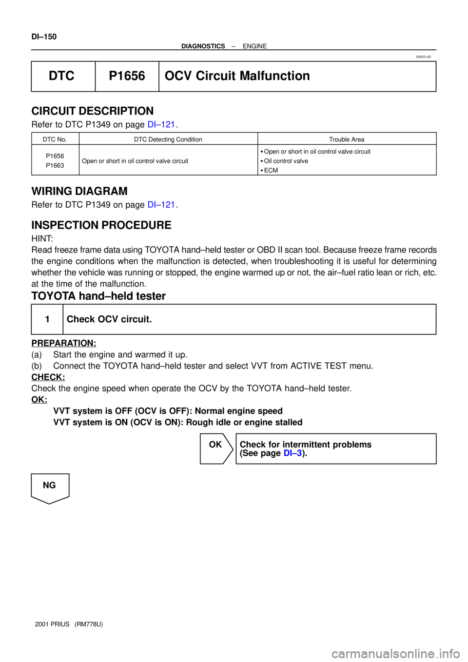
1 Check OCV circuit.
PREPARATION:
(a) Start the engine and warmed it up.
(b) Connect the TOYOTA hand±held tester and select VVT from ACTIVE TEST menu.
CHECK:
Check the engine speed when operate the OCV by the TOYOTA hand±held tester.
OK:
VVT system is OFF (OCV is OFF): Normal engine speed
VVT system is ON (OCV is ON): Rough idle or engine stalled
OK Check for intermittent problems
(See page DI±3).
NG
DI6VO±02
Page 751 of 1943

± DIAGNOSTICSENGINE
DI±153
2001 PRIUS (RM778U)
DTC P3190 Poor Engine Power
DTC P3191 Engine dose not Start
CIRCUIT DESCRIPTION
From the HV ECU, the ECM receives data such as power output required for the engine (required output),
estimated torque produced by the engine (estimated torque), engine RPM of control target (target RPM),
whether the engine is in start mode or not. Then, based on the required output and target RPM, the ECM
calculates a target torque that is to be produced by the engine and compares it with the estimated torque.
If the estimated torque is very low compared with the target torque, or the engine start mode continues at
the engine RPM or for the duration calculated by water temperature, an abnormal condition is detected.
DTC No.DTC Detecting ConditionTrouble Area
P3190
Following condition (a) to (e) continues at a fixed engine RPM
or a fixed length of time:
(a) Communication with HV ECU is normal.
(b) Engine RPM is a fixed value or more.
(c) Engine star mode is not active.
(d) Target torque is a fixed value or more.
(e) Ratio of estimated torque against target torque is less than
20 %.
�Air induction system
�Throttle body
�Fuel pressure
�Engine
�Air flow meter
�Out of fuel
Wt t
P3191
Following condition (a) to (c) continues at a fixed engine RPM
or for a fixed length of time:
(a) Vommunication with HV ECU is normal.
(b) Engine RPM is a fixed value or more.
(c) Engine start mode is active.�Water temp. sensor
�Crankshaft position sensor
�Camshaft position sensor
�ECM
WIRING DIAGRAM
Refer to DTC P1636 on page DI±146.
INSPECTION PROCEDURE
1 Are there any other codes begin output?
YES Go to relevant DTC chart.
NO
DI7T6±01