2001 TOYOTA PRIUS air condition
[x] Cancel search: air conditionPage 769 of 1943

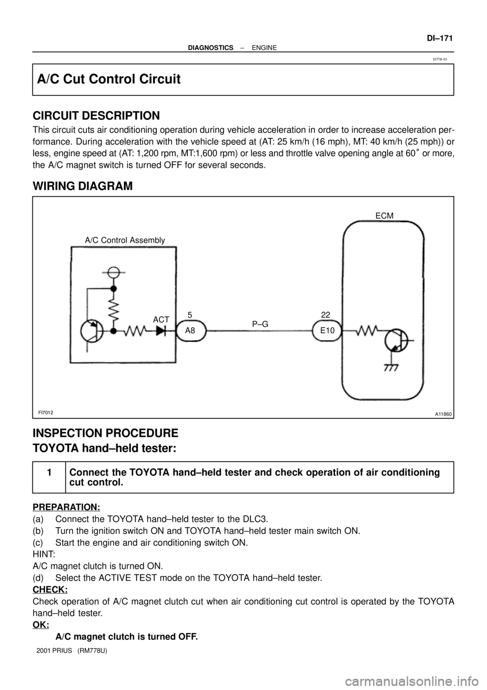
FI7012A11860
P±G A/C Control Assembly
A8 E10522
ACTECM
± DIAGNOSTICSENGINE
DI±171
2001 PRIUS (RM778U)
A/C Cut Control Circuit
CIRCUIT DESCRIPTION
This circuit cuts air conditioning operation during vehicle acceleration in order to increase acceleration per-
formance. During acceleration with the vehicle speed at (AT: 25 km/h (16 mph), MT: 40 km/h (25 mph)) or
less, engine speed at (AT: 1,200 rpm, MT:1,600 rpm) or less and throttle valve opening angle at 60° or more,
the A/C magnet switch is turned OFF for several seconds.
WIRING DIAGRAM
INSPECTION PROCEDURE
TOYOTA hand±held tester:
1 Connect the TOYOTA hand±held tester and check operation of air conditioning
cut control.
PREPARATION:
(a) Connect the TOYOTA hand±held tester to the DLC3.
(b) Turn the ignition switch ON and TOYOTA hand±held tester main switch ON.
(c) Start the engine and air conditioning switch ON.
HINT:
A/C magnet clutch is turned ON.
(d) Select the ACTIVE TEST mode on the TOYOTA hand±held tester.
CHECK:
Check operation of A/C magnet clutch cut when air conditioning cut control is operated by the TOYOTA
hand±held tester.
OK:
A/C magnet clutch is turned OFF.
DI7T8±01
Page 770 of 1943

A14008
START
(±)
(+)ACT
DI±172
± DIAGNOSTICSENGINE
2001 PRIUS (RM778U)
OK Proceed to next circuit inspection shown on
problem symptom table. (See page DI±22)
NG
2 Check for open and short in harness and connector between ECM and A/C am-
plifier. (See page IN±41)
NG Repair or replace harness or connector.
OK
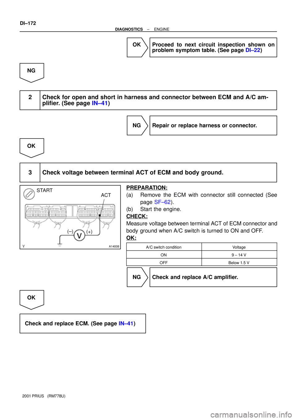
3 Check voltage between terminal ACT of ECM and body ground.
PREPARATION:
(a) Remove the ECM with connector still connected (See
page SF±62).
(b) Start the engine.
CHECK:
Measure voltage between terminal ACT of ECM connector and
body ground when A/C switch is turned to ON and OFF.
OK:
A/C switch conditionVoltage
ON9 ± 14 V
OFFBelow 1.5 V
NG Check and replace A/C amplifier.
OK
Check and replace ECM. (See page IN±41)
Page 771 of 1943

A14008
START
(±)
(+)ACT
± DIAGNOSTICSENGINE
DI±173
2001 PRIUS (RM778U)
OBDII scan tool (excluding TOYOTA hand±held tester):
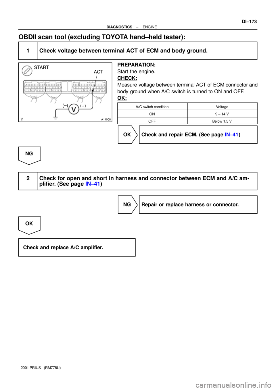
1 Check voltage between terminal ACT of ECM and body ground.
PREPARATION:
Start the engine.
CHECK:
Measure voltage between terminal ACT of ECM connector and
body ground when A/C switch is turned to ON and OFF.
OK:
A/C switch conditionVoltage
ON9 ± 14 V
OFFBelow 1.5 V
OK Check and repair ECM. (See page IN±41)
NG
2 Check for open and short in harness and connector between ECM and A/C am-
plifier. (See page IN±41)
NG Repair or replace harness or connector.
OK
Check and replace A/C amplifier.
Page 784 of 1943

F12396
TOYOTA hand±held tester
DLC3
± DIAGNOSTICSHYBRID VEHICLE CONTROL SYSTEM
DI±187
2001 PRIUS (RM778U)
(d) Clear the DTC after completion of repair.
(1) Connect the TOYOTA hand±held tester to the
DLC3.
Before clearing, check that DTCs and freeze frame
data of the HV ECU and the ECU related to the op-
eration history data are reccorded.
(2) Operate the TOYOTA hand±held tester to erase the
DTC (See the hand±held tester operator's manu-
al.).
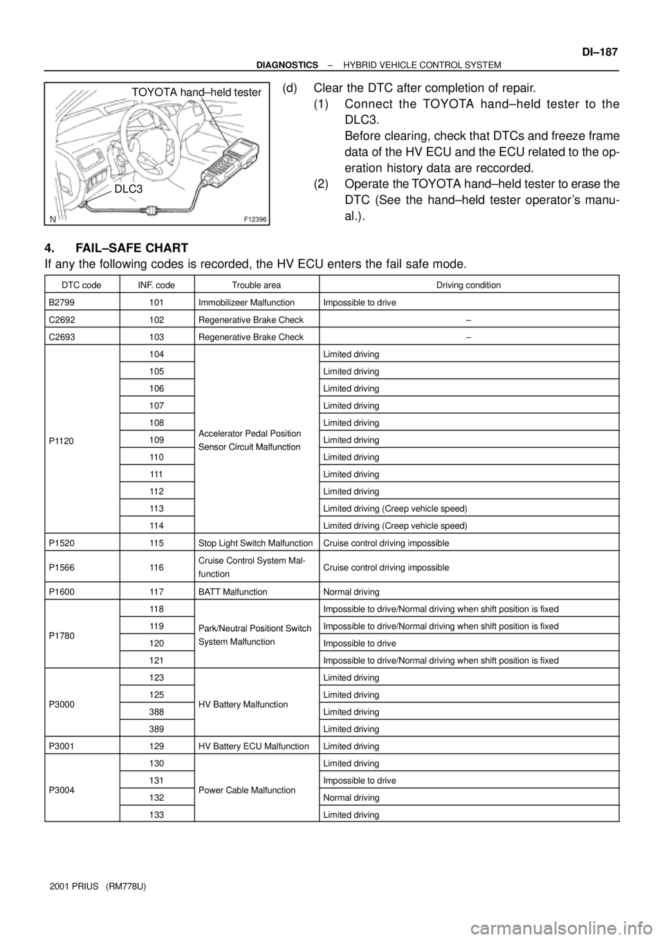
4. FAIL±SAFE CHART
If any the following codes is recorded, the HV ECU enters the fail safe mode.
DTC codeINF. codeTrouble areaDriving condition
B2799101Immobilizeer MalfunctionImpossible to drive
C2692102Regenerative Brake Check±
C2693103Regenerative Brake Check±
104Limited driving
105Limited driving
106Limited driving
107Limited driving
108Limited driving
P1120109Accelerator Pedal Position
Sensor Circuit MalfunctionLimited drivingP1120
11 0Sensor Circuit MalfunctionLimited driving
111Limited driving
11 2Limited driving
11 3Limited driving (Creep vehicle speed)
11 4Limited driving (Creep vehicle speed)
P152011 5Stop Light Switch MalfunctionCruise control driving impossible
P156611 6Cruise Control System Mal-
functionCruise control driving impossible
P160011 7BATT MalfunctionNormal driving
11 8Impossible to drive/Normal driving when shift position is fixed
P178011 9Park/Neutral Positiont SwitchImpossible to drive/Normal driving when shift position is fixedP1780120
Park/Neutral Positiont Switch
System MalfunctionImpossible to drive
121
y
Impossible to drive/Normal driving when shift position is fixed
123Limited driving
P3000125HV B tt M lf tiLimited drivingP3000388HV Battery MalfunctionLimited driving
389Limited driving
P3001129HV Battery ECU MalfunctionLimited driving
130Limited driving
P3004131PCblMlftiImpossible to driveP3004132Power Cable MalfunctionNormal driving
133Limited driving
Page 790 of 1943

± DIAGNOSTICSHYBRID VEHICLE CONTROL SYSTEM
DI±193
2001 PRIUS (RM778U)
5. CHECK FOR INTERMITTENT PROBLEMS
(a) Perform a simulation test (See page IN±41).
In the simulation test, reproduce the driving condition at the trouble occurrence according to the cus-
tomer 's comments and freeze frame data recorded with DTC, such as an opening angle of the acceler-
ator pedal, SOC, engine coolant temperature, engine rpm, and MG/1MG2 rpm and torque.
(b) Check the connector and terminal (See page IN±41).
(c) Handle the connector (See page IN±41).
6. TOYOTA HAND±HELD TESTER DISPLAY ITEMS
TOYOTA Hand±held tester displayMeasurement Item
1 BEF LATST ORNumber of operation of 1 trip before last
1 BEF LATST TRPNumber of trips before last
2 BEF LATST ORNumber of operation 2 trips before last
2 BEF LATST TRPNumber of trips 2 before last
ABNML CON BR±HVCommunication malfunction between HV ECU and brake
ACC SENSOR MAINMain accelerator sensor
ACC SENSOR SUBSub accelerator sensor
ACC TENT TRBLETentative trouble of accelerator
ACC THROTTLEAccelerator throttle
ACCEL MODEHistory of acceleration and reduction
AIR CON REQUESTAir conditioner request
AUX. BATT LOWAuxiliary battery becomes week
AUX. BATT VVoltage of auxiliary battery
BATT HIGH TEMPTemperature of the battery is too high
BATT HIGH VOLTVoltage of the battery is too high
BATT LOW BOLTVoltage of the battery is low
BATT OVER LOADBattery is overloaded
BATT SAVE RQSTRequest to save the main battery
BATTERY FULLBattery full
BRAKE TORQBrake torque
CELL TEMP±MAXHighest temperature of all battery cells
CELL TEMP±MINLowest temperature of all battery cells
CHG RESTRICTIONCharge restriction
COOLANT TEMPWater temperature
CRUISE CONTROLCondition of the cruise control
DC/DC CONV STOPDC/DC converter stop signal
DC/DC CONV STOPFactors causing DC/DC converter to stop
DC/DC STOP FACTDC/DC converter has stopped at least once
DC/DC V UNSETDC/DC voltage is unsettled
DCHG RQST SOCDischarge request to adjust SOC
DISCHAG INHIBITBattery is inhibited to discharge
Page 791 of 1943

DI±194
± DIAGNOSTICSHYBRID VEHICLE CONTROL SYSTEM
2001 PRIUS (RM778U)
0: When engine is stopped
1: When stopping engine
2: When starting engine
DRIVE CONDITION3: When cranking engine or engine is operatingDRIVE CONDITION
4: While generating power or load driving
5: ±
6: While racing engine in P position
DRIVING PATTEN1History of driving pattern 1
DRIVING PATTEN2History of driving pattern 2
DRIVING PATTEN3History of driving pattern 3
DRIVING PATTERNHIstory of driving
ECU TYPEECU type
ENG INDPDET RQFactors causing engine to run independently
ENG STOP RQSTEngine stop request
ENG STP INHIBITEngine stop inhibition
ENG WARM UP RQTEngine warming up request
ENGINE FUEL CUTEngine fuel cut
ENGINE SPDEngine speed
EXCLUSIVE INFO1Exclusive information 1
EXCLUSIVE INFO2Exclusive information 2
EXCLUSIVE INFO3Exclusive information 3
EXCLUSIVE INFO4Exclusive information 4
EXCLUSIVE INFO5Exclusive information 5
EXCLUSIVE INFO6Exclusive information 6
FUEL SHORTAGELow fuel
HCAC ABSRT RQSTHCAC OBD request
HV BATT CH RQSTRequest from HV ECU to charge the battery
HV ECU INTERMITTENTHV ECU intermittent problems
IDLING REQUESTEngine idling request
IG OFF IN DRVINTurning IG OFF while driving the car
IG OFF TIMEIG OFF time
ILK OPERATIONInterlock operation
INFORMATION 1±5Information code
INPUT V LOWInput voltage is too low
INPUT V OVERInput voltage is too high
INTAKE AIRIntake air temperature
INVERT TEMP±MG1Temperature of inverter MG1
INVERT TEMP±MG2Temperature of inverter MG2
LATEST OPERLatest number of operation
LATEST TRIPLatest number of trips (IG ON±OFF)
LOAD CONDITIONIndicating which of MG1 or MG2 the vehicle uses more
MAIN BATT LOWSOC of main battery becomes low
MCYL CTRL POWERTorque for controlling oil pressure of master cylinder
MG1 TEMP HIGHTemperature MG1 is too high
MG2 TEMP HIGHTemperature MG2 is too high
MG1 CURRENT VElectric current of MG1 V phase
Page 799 of 1943

DI±202
± DIAGNOSTICSHYBRID VEHICLE CONTROL SYSTEM
2001 PRIUS (RM778U)DTC NO.
INF. CodeDetection ItemDetecting Condition
209
210When communication between ECM and HV ECU is abnormal 1 sec. after
ignition is turned ON
P3106211ECM Communication Circuit
Malfunction
ignition is turned ON
P3106
212MalfunctionInput of abnormal signal from ECM
394When ECM does not operate
213
P3107214Airbag ECU Communication
Circuit Malfunction
When communication between airbag ECU and HV ECU is abnormal 10
sec after ignition is turned ONP3107
215Circuit Malfunctionsec. after ignition is turned ON
P3108216A/C Amplifier CommunicationWh i ti f A/C lifi t HV ECU i b lP3108217
A/C Am lifier Communication
Circuit MalfunctionWhen communication from A/C amplifier to HV ECU is abnormal
218
219When communication between brake ECU and HV ECU is abnormal 1.5
P3109220Brake ECU Communication
Circuit Malfunction
When communication between brake ECU and HV ECU is abnormal 1.5
sec. after ignition is turned ONP3109
221Circuit Malfunctiong
222When abnormal data is received from brake ECU
P3110223IGCT RelayWhen IGCT relay is always closed
224SMR C t1 M lf tiOpen or +B short in system main relay No. 1 circuit
225SMR Cont1 MalfunctionShort in system main relay No. 1 circuit
226SMR C t2 M lf tiOpen or +B short in system main relay No. 2 circuit
227SMR Cont2 MalfunctionShort in system main relay No. 2 circuit
P3115228SMR C t3 M lf tiOpen or +B short in system main relay No. 3 circuitP3115
229SMR Cont3 MalfunctionShort in system main relay No. 3 circuit
231System main relay + terminal deposited
232Deposit of SMRSystem main relay ± terminal deposited
233
De osit of SMR
System main relay + & ± terminal deposited
234Small reduction of motor magnetism
235E B l M lf tiLarge reduction of motor magnetism
236Energy Balance MalfunctionSmall reduction of generator magnetism
237Large reduction of generator magnetism
239Shaft damaged
240HV T l M lf tiGenerator locked
P3120241HV Transaxle MalfunctionTorque limiter slidingP3120242Planetary gear locked
243Motor resolver inter±phase short
244
Mt R l Mlf ti
Motor resolver inter±phase short (When there is a history that the state of
malfunction continued during inverter fail safe mode)
245Motor Resolver MalfunctionOpen or short in motor resolver circuit
246Open or short in motor resolver circuit (When there is a history that the
state of malfunction continued during inverter fail safe mode)
Page 801 of 1943

DI±204
± DIAGNOSTICSHYBRID VEHICLE CONTROL SYSTEM
2001 PRIUS (RM778U)DTC NO.
INF. CodeDetection ItemDetecting Condition
288Motor inverter current sensor malfunction (V phase sub sensor)
289Open in motor inverter current sensor (V phase sub sensor)
290Motor inverter current sensor malfunction (V phase main sensor)
291(when there is a history that the state of malfunction continued during in-
verter fail safe mode)
292Open in motor inverter current sensor (V phase main sensor)
293(when there is a history that the state of malfunction continued during in-
verter fail safe mode)
294Mt I t C tSMotor inverter current sensor V phase performance problem
295
Motor Inverter Current Sen-
sor Malfunction(when there is a history that the state of malfunction continued during in-
verter fail safe mode)
296Motor inverter current sensor malfunction (W phase sub sensor)
297Open in motor inverter current sensor (W phase sub sensor)
298Motor inverter current sensor malfunction (W phase main sensor)
299(when there is a history that the state of malfunction continued during in-
verter fail safe mode)
300Open in motor inverter current sensor (W phase main sensor)
301(when there is a history that the state of malfunction continued during in-
verter fail safe mode)
302Mt I t C tSMotor inverter current sensor W phase performance problem
303
Motor Inverter Current Sen-
sor Malfunction(when there is a history that the state of malfunction continued during in-
verter fail safe mode)
304Motor Gate Shutdown Signal+B short in motor gate shutdown signal circuit
P3125305
Motor Gate Shutdown Signal
Line Connection MalfunctionOpen or GND short in motor gate shutdown signal circuitP3125
306Failure in Monitoring Motor
Torque PerformanceFailure in monitoring motor torque performance
307Abnormal Current Value of
MotorAbnormal current value of motor
308Detection of Collision SignalInput of collision signal from airbag or inverter
309Motor PWM Line Connection
MalfunctionOpen or short in generator inverter switching wiring (GUU, GVU, GWU)
311Generator Inverter Malfunc-
tionGenerator inverter malfunction
312Open or +B short in generator inverter temperature sensor
313Generator Inverter Tempera-GND short in generator inverter temperature sensor
314
Generator Inverter Tem era
ture Sensor MalfunctionGenerator inverter temperature sensor malfunction
315Generator inverter temperature sensor performance problem
316+B short in generator inverter stop signal circuit
317Over voltage of inverter
318Generator Inverter SinvOpen or GND short in generation inverter stop signal circuit
319
Generator Inverter Sinv
Voltage drop of inverter power source
320Inverter circuit broken
321+B short in generator inverter fail signal circuit
322Inverter overheating
323Generator Inverter FinvOpen or GND short in generator inverter fail signal circuit
324
Generator Inverter Finv
Inverter circuit broken
325Inverter internal short