Page 1767 of 1943

BE±10
± BODY ELECTRICALTROUBLESHOOTING
1677 Author�: Date�:
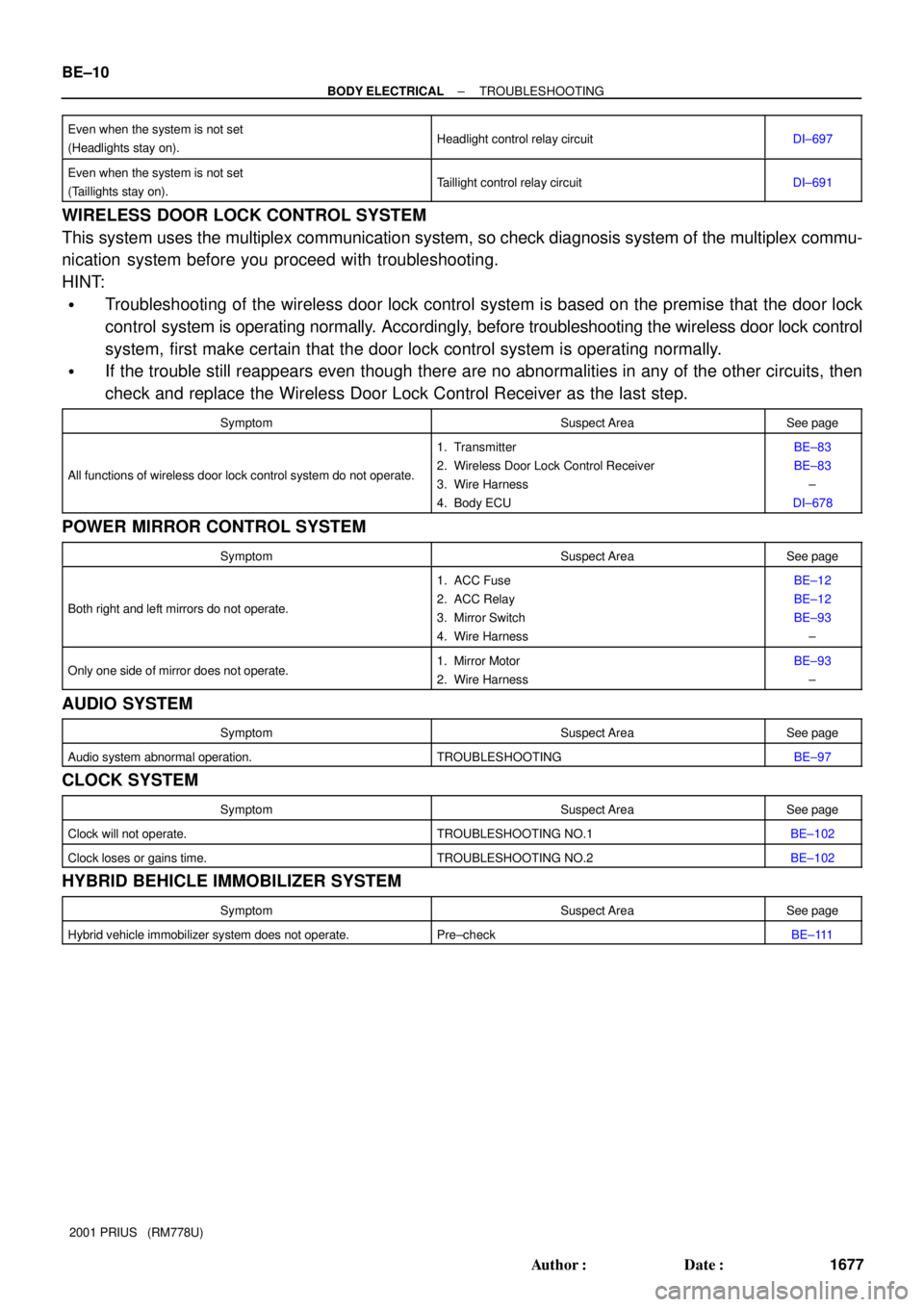
2001 PRIUS (RM778U) Even when the system is not set
(Headlights stay on).
Headlight control relay circuitDI±697
Even when the system is not set
(Taillights stay on).Taillight control relay circuitDI±691
WIRELESS DOOR LOCK CONTROL SYSTEM
This system uses the multiplex communication system, so check diagnosis system of the multiplex commu-
nication system before you proceed with troubleshooting.
HINT:
�Troubleshooting of the wireless door lock control system is based on the premise that the door lock
control system is operating normally. Accordingly, before troubleshooting the wireless door lock control
system, first make certain that the door lock control system is operating normally.
�If the trouble still reappears even though there are no abnormalities in any of the other circuits, then
check and replace the Wireless Door Lock Control Receiver as the last step.
SymptomSuspect AreaSee page
All functions of wireless door lock control system do not operate.
1. Transmitter
2. Wireless Door Lock Control Receiver
3. Wire Harness
4. Body ECUBE±83
BE±83
±
DI±678
POWER MIRROR CONTROL SYSTEM
SymptomSuspect AreaSee page
Both right and left mirrors do not operate.
1. ACC Fuse
2. ACC Relay
3. Mirror Switch
4. Wire HarnessBE±12
BE±12
BE±93
±
Only one side of mirror does not operate.1. Mirror Motor
2. Wire HarnessBE±93
±
AUDIO SYSTEM
SymptomSuspect AreaSee page
Audio system abnormal operation.TROUBLESHOOTINGBE±97
CLOCK SYSTEM
SymptomSuspect AreaSee page
Clock will not operate.TROUBLESHOOTING NO.1BE±102
Clock loses or gains time.TROUBLESHOOTING NO.2BE±102
HYBRID BEHICLE IMMOBILIZER SYSTEM
SymptomSuspect AreaSee page
Hybrid vehicle immobilizer system does not operate.Pre±checkBE±111
Page 1799 of 1943

Z05930
1
2
3
5 1
5
2 3
I1535121
I1535221
I15353
2
1
I153542
1
± BODY ELECTRICALPOWER WINDOW CONTROL SYSTEM
BE±57
2001 PRIUS (RM778U)
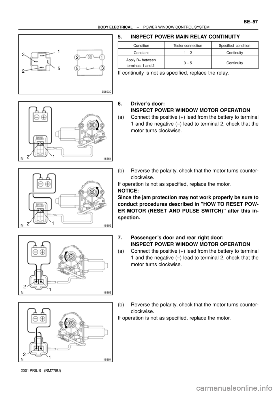
5. INSPECT POWER MAIN RELAY CONTINUITY
ConditionTester connectionSpecified condition
Constant1 ± 2Continuity
Apply B+ between
terminals 1 and 2.3 ± 5Continuity
If continuity is not as specified, replace the relay.
6. Driver 's door:
INSPECT POWER WINDOW MOTOR OPERATION
(a) Connect the positive (+) lead from the battery to terminal
1 and the negative (±) lead to terminal 2, check that the
motor turns clockwise.
(b) Reverse the polarity, check that the motor turns counter-
clockwise.
If operation is not as specified, replace the motor.
NOTICE:
Since the jam protection may not work properly be sure to
conduct procedures described in ºHOW TO RESET POW-
ER MOTOR (RESET AND PULSE SWITCH)º after this in-
spection.
7. Passenger 's door and rear right door:
INSPECT POWER WINDOW MOTOR OPERATION
(a) Connect the positive (+) lead from the battery to terminal
1 and the negative (±) lead to terminal 2, check that the
motor turns clockwise.
(b) Reverse the polarity, check that the motor turns counter-
clockwise.
If operation is not as specified, replace the motor.
Page 1800 of 1943

I15357
2
1
I15358
2
1
I14317
21
I1431821
I14319
21
BE±58
± BODY ELECTRICALPOWER WINDOW CONTROL SYSTEM
2001 PRIUS (RM778U)
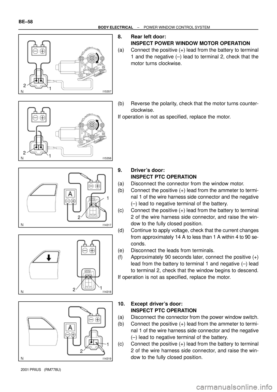
8. Rear left door:
INSPECT POWER WINDOW MOTOR OPERATION
(a) Connect the positive (+) lead from the battery to terminal
1 and the negative (±) lead to terminal 2, check that the
motor turns clockwise.
(b) Reverse the polarity, check that the motor turns counter-
clockwise.
If operation is not as specified, replace the motor.
9. Driver 's door:
INSPECT PTC OPERATION
(a) Disconnect the connector from the window motor.
(b) Connect the positive (+) lead from the ammeter to termi-
nal 1 of the wire harness side connector and the negative
(±) lead to negative terminal of the battery.
(c) Connect the positive (+) lead from the battery to terminal
2 of the wire harness side connector, and raise the win-
dow to the fully closed position.
(d) Continue to apply voltage, check that the current changes
from approximately 14 A to less than 1 A within 4 to 90 se-
conds.
(e) Disconnect the leads from terminals.
(f) Approximately 90 seconds later, connect the positive (+)
lead from the battery to terminal 1 and negative (±) lead
to terminal 2, check that the window begins to descend.
If operation is not as specified, replace the motor.
10. Except driver's door:
INSPECT PTC OPERATION
(a) Disconnect the connector from the power window switch.
(b) Connect the positive (+) lead from the ammeter to termi-
nal 1 of the wire harness side connector and the negative
(±) lead to negative terminal of the battery.
(c) Connect the positive (+) lead from the battery to terminal
2 of the wire harness side connector, and raise the win-
dow to the fully closed position.
Page 1802 of 1943

BE1W7±01
I03147
I11689
LOCK
UNLOCK
I11690
LOCK
UNLOCK
I11689UNLOCKLOCK
I11690UNLOCK LOCK BE±62
± BODY ELECTRICALPOWER DOOR LOCK CONTROL SYSTEM
2001 PRIUS (RM778U)
INSPECTION
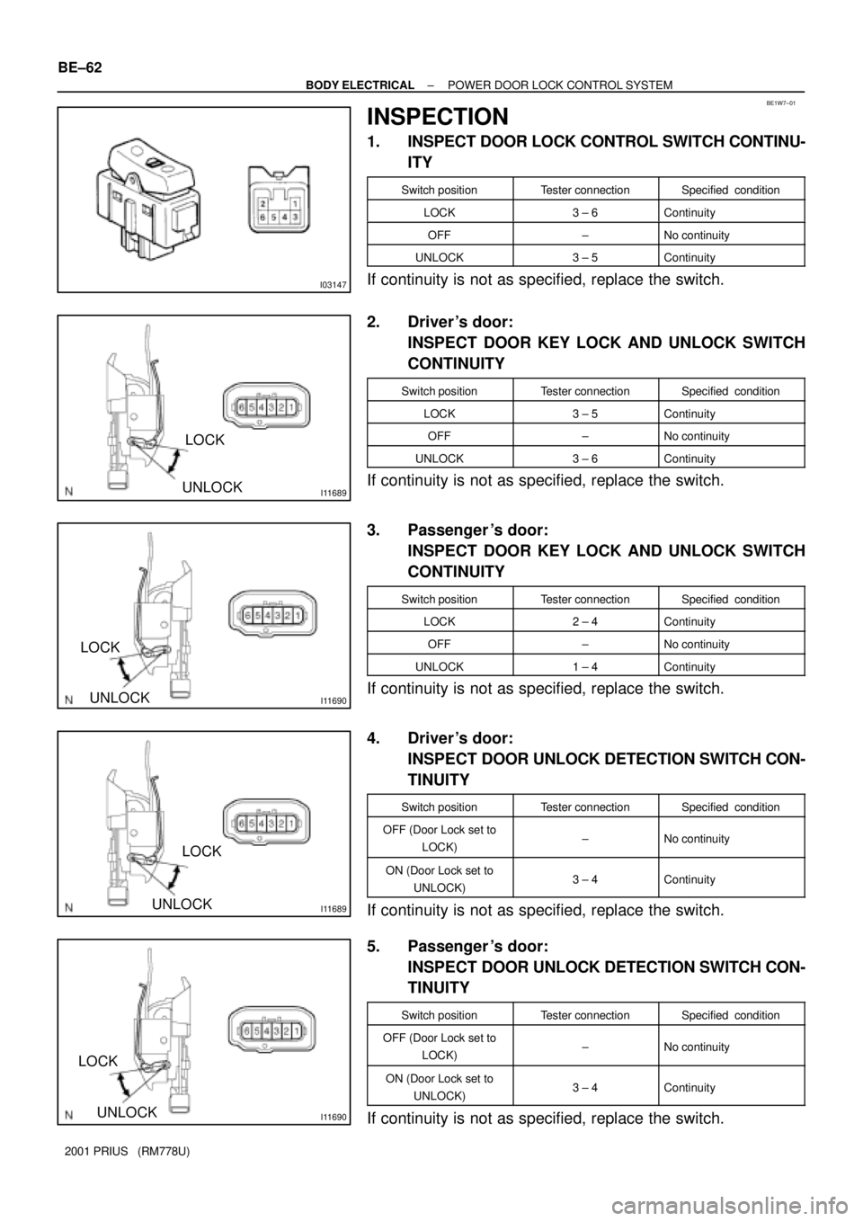
1. INSPECT DOOR LOCK CONTROL SWITCH CONTINU-
ITY
Switch positionTester connectionSpecified condition
LOCK3 ± 6Continuity
OFF±No continuity
UNLOCK3 ± 5Continuity
If continuity is not as specified, replace the switch.
2. Driver 's door:
INSPECT DOOR KEY LOCK AND UNLOCK SWITCH
CONTINUITY
Switch positionTester connectionSpecified condition
LOCK3 ± 5Continuity
OFF±No continuity
UNLOCK3 ± 6Continuity
If continuity is not as specified, replace the switch.
3. Passenger 's door:
INSPECT DOOR KEY LOCK AND UNLOCK SWITCH
CONTINUITY
Switch positionTester connectionSpecified condition
LOCK2 ± 4Continuity
OFF±No continuity
UNLOCK1 ± 4Continuity
If continuity is not as specified, replace the switch.
4. Driver 's door:
INSPECT DOOR UNLOCK DETECTION SWITCH CON-
TINUITY
Switch positionTester connectionSpecified condition
OFF (Door Lock set to
LOCK)±No continuity
ON (Door Lock set to
UNLOCK)3 ± 4Continuity
If continuity is not as specified, replace the switch.
5. Passenger 's door:
INSPECT DOOR UNLOCK DETECTION SWITCH CON-
TINUITY
Switch positionTester connectionSpecified condition
OFF (Door Lock set to
LOCK)±No continuity
ON (Door Lock set to
UNLOCK)3 ± 4Continuity
If continuity is not as specified, replace the switch.
Page 1803 of 1943
I07301
LOCK
I07302
LOCK
I14313
UNLOCKLOCK
UNLOCK LOCK
22
11
± BODY ELECTRICALPOWER DOOR LOCK CONTROL SYSTEM
BE±63
2001 PRIUS (RM778U)
6. Rear left door:
INSPECT DOOR UNLOCK DETECTION SWITCH CON-
TINUITY
Switch positionTester connectionSpecified condition
OFF±No continuity
ON1 ± 2Continuity
If continuity is not as specified, replace the switch.
7. Rear right door:
INSPECT DOOR UNLOCK DETECTION SWITCH CON-
TINUITY
Switch positionTester connectionSpecified condition
OFF±No continuity
ON3 ± 4Continuity
If continuity is not as specified, replace the switch.
8. Driver 's door:
INSPECT DOOR LOCK MOTOR OPERATION
(a) Connect the positive (+) lead from the battery to terminal
1 and the negative (±) lead to terminal 2, and check that
the door lock link moves to UNLOCK position.
(b) Reverse the polarity and check that the door lock link
moves to LOCK position.
If operation is not as specified, replace the door lock assembly.
Page 1804 of 1943
I14314
UNLOCKLOCK
UNLOCK LOCK
6565
I07299
LOCK
UNLOCK
UNLOCKLOCK
2
11
2 BE±64
± BODY ELECTRICALPOWER DOOR LOCK CONTROL SYSTEM
2001 PRIUS (RM778U)
9. Passenger 's door:
INSPECT DOOR LOCK MOTOR OPERATION
(a) Connect the positive (+) lead from the battery to terminal
5 and the negative (±) lead to terminal 6, and check that
the door lock link moves to UNLOCK position.
(b) Reverse the polarity and check that the door lock link
moves to LOCK position.
If operation is not as specified, replace the door lock assembly.
10. Rear left door:
INSPECT DOOR LOCK MOTOR OPERATION
(a) Connect the positive (+) lead from the battery to terminal
1 and the negative (±) lead to terminal 2, and check that
the door lock link moves to UNLOCK position.
(b) Reverse the polarity and check that the door lock link
moves to LOCK position.
If operation is not as specified, replace the door lock assembly.
Page 1805 of 1943
I07300
LOCK
UNLOCK
UNLOCKLOCK
4
343
± BODY ELECTRICALPOWER DOOR LOCK CONTROL SYSTEM
BE±65
2001 PRIUS (RM778U)
11. Rear right door:
INSPECT DOOR LOCK MOTOR OPERATION
(a) Connect the positive (+) lead from the battery to terminal
3 and the negative (±) lead to terminal 4, and check that
the door lock link moves to UNLOCK position.
(b) Reverse the polarity and check that the door lock link
moves to LOCK position.
If operation is not as specified, replace the door lock assembly.
Page 1806 of 1943

DI7T9±01
± BODY ELECTRICALTHEFT DETERRENT SYSTEM
BE±67
2001 PRIUS (RM778U)
PRE±CHECK
1. OUT LINE OF THEFT DETERRENT SYSTEM
When the theft deterrent system detects any theft, it informs
people around with flashing lights and sound.
This system is designed to be upgraded by featuring an option-
al glass break sensor.
All initial setting are performed in active mode. It can be
switched to passive mode by specified operation. (See step 3.
CHANGING METHOD OF PASSIVE MODE)
HINT:
There are 4 conditions in this system which are disarmed state,
arming preparation, armed state and alarm sounding.
(1) Disarmed state
�When the alarming function does not oper-
ate.
�When theft deterrent function is not per-
formed.
(2) Arming preparation
�Time until transferring to armed state.
�Theft deterrent function is not performed.
(3) Armed state
When theft deterrent function is possible.
(4) Alarm sounding:
In this condition, once theft is detected, it is in-
formed using light and sound to people around the
vehicle.
Refer to the table for alarming method or time.
Horn
Security horn
Al i th dHeadlightAlarming methodTaillight
Hazard
Interior light
Alarming time60 seconds
Alarming outputContinuous 0.4 secs. (ON)
0.4 secs. (OFF)
HINT:
Alarming output for hazard is same as the one for the hazard
on the vehicle.
In the arming condition when either of doors is unlocked with
key not in the key cylinder, force lock signal is output.