Page 1700 of 2572

316 Author�: Date�:
2005 HIGHLANDER REPAIR MANUAL (RM1144U)
1 CHECK OTHER DTC OUTPUT
(a) Read the DTC using the hand-held tester")
A81695
E8
ECM
O1B-
OX1B
HT1B
05-126
- DIAGNOSTICSSFI SYSTEM (2AZ-FE)
316 Author�: Date�:
2005 HIGHLANDER REPAIR MANUAL (RM1144U)
1 CHECK OTHER DTC OUTPUT
(a) Read the DTC using the hand-held tester or the OBD II scan tool.
Result:
Display (DTC Output)Proceed to
P0138 is outputA
P0137 is outputB
P0136 is outputC
HINT:
If any other codes besides P0136, P0137 and/or P138 are output, perform the troubleshooting for those
codes first.
B Go to step 9
C Go to step 6
A
2 READ VALUE OF HAND-HELD TESTER OR OBD II SCAN TOOL (OUTPUT
VOLTAGE OF HEATED OXYGEN SENSOR)
(a) Connect the hand-held tester or the OBD II scan tool to the DLC3.
(b) Turn ON the ignition switch. Push the hand-held tester or the OBD II scan tool main switch ON.
(c) Enter the following menus: DIAGNOSIS / ENHANCED OBD II / DATA LIST / ALL / O2S B1S2.
(d) Run the engine at idle.
(e) Read the output voltage of the heated oxygen sensor during idling.
Heated oxygen sensor output voltageProceed to
More than 1.2 VA
Less than 1.0 VB
B READ OUTPUT DTC
A
3 CHECK WIRE HARNESS (CHECK FOR SHORT)
(a) Turn the ignition switch OFF and wait for 5 minutes.
(b) Disconnect the E8 ECM connector.
(c) Measure the resistance of the wire harness side connec-
tors.
Standard:
Tester ConnectionSpecified Condition
E8-21 (HT1B) - E8-29 (OX1B)10 kW or higher
E8-21 (HT1B) - E8-2 (O1B-)10 kW or higher
OK REPLACE ECM (See page 10-9)
NG
Page 1701 of 2572

05-127
317 Author�: Date�:
2005 HIGHLANDER REPAIR MANUAL (RM1144U)
4 INSPECT HEATED OXYGEN SENSOR (CHECK FOR SHORT)
(a) Dis")
A80018
H10
Heated Oxygen Sensor
E1 OX
+B
- DIAGNOSTICSSFI SYSTEM (2AZ-FE)
05-127
317 Author�: Date�:
2005 HIGHLANDER REPAIR MANUAL (RM1144U)
4 INSPECT HEATED OXYGEN SENSOR (CHECK FOR SHORT)
(a) Disconnect the H10 heated oxygen sensor connector.
(b) Measure the resistance of the sensor side connectors.
Standard:
Tester ConnectionSpecified Condition
H10-1 (+B) - H10-3 (E1)10 kW or higher
H10-1 (+B) - H10-4 (OX)10 kW or higher
OK REPAIR OR REPLACE HARNESS AND
CONNECTOR
NG
REPLACE HEATED OXYGEN SENSOR
5 READ OUTPUT DTC (CHECK MODE)
(a) Change the ECM to check mode with the hand-held tester.
Enter the following menus: DIAGNOSIS / ENHANCED OBD II / CHECK MODE.
(b) Warm up the engine and drive the vehicle at over 25 mph (40 km/h) for an accumulated total of 10
minutes.
HINT:
The 10 minutes of driving should be driven in one instance, but it is not necessary to maintain a speed of
25 mph (40 km/h) for 10 minutes consecutively.
(c) Read the DTC.
Result:
Display (DTC output)Proceed to
P0136 is outputA
No DTCB
B CHECK FOR INTERMITTENT PROBLEMS
(See page 05-9)
A
REPLACE HEATED OXYGEN SENSOR
6 READ VALUE OF HAND-HELD TESTER OR OBD II SCAN TOOL (OUTPUT
VOLTAGE OF HEATED OXYGEN SENSOR)
(a) After warming up the engine, run the engine at 2,500 rpm for 3 minutes.
(b) Read the output voltage of the heated oxygen sensor when the engine rpm is suddenly increased.
HINT:
Quickly accelerate the engine to 4,000 rpm 3 times by using the accelerator pedal.
Heated oxygen sensor output voltage: Alternates 0.4 V or less and 0.5 V or more.
OK Go to step 10
NG
Page 1702 of 2572
A80018
H10
Heated Oxygen Sensor
+B HT
E1 OX
B60778
5
12 312
5
3
05-128
- DIAGNOSTICSSFI SYSTEM (2AZ-FE)
318 Author�: Date�:
2005 HIGHLANDER REPAIR MANUAL (RM1144U)
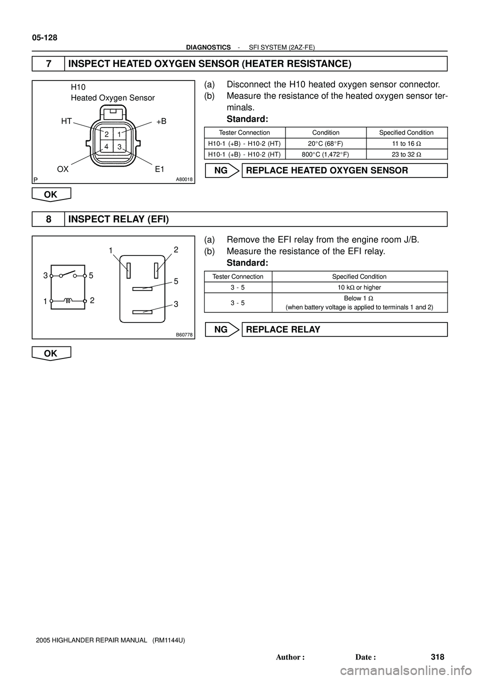
7 INSPECT HEATED OXYGEN SENSOR (HEATER RESISTANCE)
(a) Disconnect the H10 heated oxygen sensor connector.
(b) Measure the resistance of the heated oxygen sensor ter-
minals.
Standard:
Tester ConnectionConditionSpecified Condition
H10-1 (+B) - H10-2 (HT)20�C (68�F)11 to 16 W
H10-1 (+B) - H10-2 (HT)800�C (1,472�F)23 to 32 W
NG REPLACE HEATED OXYGEN SENSOR
OK
8 INSPECT RELAY (EFI)
(a) Remove the EFI relay from the engine room J/B.
(b) Measure the resistance of the EFI relay.
Standard:
Tester ConnectionSpecified Condition
3 - 510 kW or higher
3 - 5Below 1 W
(when battery voltage is applied to terminals 1 and 2)
NG REPLACE RELAY
OK
Page 1703 of 2572
A80019
A81695A92146
Wire Harness Side
HT
+B
OX
E1
HT1B
OX1B
E8
ECM H10
Heated Oxygen Sensor
A90346
Reference (Bank 1 Sensor 2 System Drawing)
Heater
Sensor
Duty
Control ECM
From
Battery
EFI NO. 1
FuseEFI Relay
+B HT
EFI NO. 2
Fuse
MREL OX1B HT1B Heated Oxygen Sensor
OB1- OX E1
- DIAGNOSTICSSFI SYSTEM (2AZ-FE)
05-129
319 Author�: Date�:
2005 HIGHLANDER REPAIR MANUAL (RM1144U)
9 CHECK WIRE HARNESS
(a) Check the wire harness between the ECM and heated ox-
ygen sensor.
(1) Disconnect the H10 heated oxygen sensor connec-
tor.
(2) Disconnect the E8 ECM connector.
(3) Measure the resistance of the wire harness side
connectors.
Standard:
Tester ConnectionSpecified Condition
H10-2 (HT) - E8-21 (HT1B)
H10-4 (OX) - E8-29 (OX1B)Below 1 W
H10-2 (HT) or E8-21 (HT1B) - Body ground
H10-4 (OX) or E8-29 (OX1B) -Body ground10 kW or higher
NG REPAIR OR REPLACE HARNESS AND
CONNECTOR
OK
Page 1704 of 2572
05-130
- DIAGNOSTICSSFI SYSTEM (2AZ-FE)
320 Author�: Date�:
2005 HIGHLANDER REPAIR MANUAL (RM1144U)
REPLACE HEATED OXYGEN SENSOR
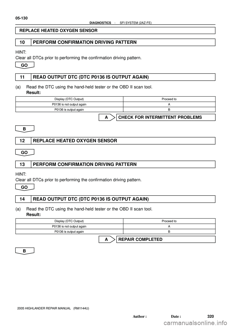
10 PERFORM CONFIRMATION DRIVING PATTERN
HINT:
Clear all DTCs prior to performing the confirmation driving pattern.
GO
11 READ OUTPUT DTC (DTC P0136 IS OUTPUT AGAIN)
(a) Read the DTC using the hand-held tester or the OBD II scan tool.
Result:
Display (DTC Output)Proceed to
P0136 is not output againA
P0136 is output againB
A CHECK FOR INTERMITTENT PROBLEMS
B
12 REPLACE HEATED OXYGEN SENSOR
GO
13 PERFORM CONFIRMATION DRIVING PATTERN
HINT:
Clear all DTCs prior to performing the confirmation driving pattern.
GO
14 READ OUTPUT DTC (DTC P0136 IS OUTPUT AGAIN)
(a) Read the DTC using the hand-held tester or the OBD II scan tool.
Result:
Display (DTC Output)Proceed to
P0136 is not output againA
P0136 is output againB
A REPAIR COMPLETED
B
Page 1705 of 2572

05-131
321 Author�: Date�:
2005 HIGHLANDE")
A87979
+12.5 %
Normal Malfunction-12.5 %
0 3.3 V
1 VA/F Sensor Output
Heated Oxygen Sensor OutputInjection Volume
Malfunction
- DIAGNOSTICSSFI SYSTEM (2AZ-FE)
05-131
321 Author�: Date�:
2005 HIGHLANDER REPAIR MANUAL (RM1144U)
15 PERFORM ACTIVE TEST USING HAND-HELD TESTER
(a) Start the engine and warm it up.
(b) Connect the hand-held tester to the DLC3.
(c) Turn ON the ignition switch and the hand-held tester main switch.
(d) Enter the following menus: DIAGNOSIS / ENHANCED OBD II / ACTIVE TEST / INJ VOL.
(e) Using the hand-held tester, change the injection volume to check the A/F sensor output and heated
oxygen sensor output values below.
HINT:
Change the injection volume from -12.5 % to +12.5 %.
Result:
A/F sensor output remains more than 3.3 V or A/F sensor output remains less than 3.3 V
(Heated oxygen sensor reacts in accordance with increase and decrease of injection volume)
OK REPLACE AIR FUEL RATIO SENSOR
NG
CHECK AND REPLACE EXTREMLY RICH OR LEAN ACTUAL AIR FUEL RATIO (INJECTOR, FUEL
PRESSURE, GAS LEAKAGE IN EXHAUST SYSTEM, ETC.)
Page 1706 of 2572

322 Author�: Date�:
2005 HIGHLANDER REPAIR MANUAL (RM1144U)
DTC P0171 SYSTEM TOO LEAN (BANK 1)
DTC P0172 SYSTEM TOO RICH (BANK 1)
CIRCUIT DESCRIPTION
The fue")
05-132
- DIAGNOSTICSSFI SYSTEM (2AZ-FE)
322 Author�: Date�:
2005 HIGHLANDER REPAIR MANUAL (RM1144U)
DTC P0171 SYSTEM TOO LEAN (BANK 1)
DTC P0172 SYSTEM TOO RICH (BANK 1)
CIRCUIT DESCRIPTION
The fuel trim is related to the feedback compensation value, not to the basic injection time. The fuel trim in-
cludes the short-term fuel trim and the long-term fuel trim.
The short-term fuel trim is the short-term fuel compensation used to maintain the ideal stoichiometric air-
fuel ratio. The signal from the A/F sensor indicates whether the air-fuel ratio is RICH or LEAN compared
to the stoichiometric air-fuel ratio. This variance triggers a reduction in the fuel volume if the air-fuel ratio
is RICH, and an increase in the fuel volume if it is LEAN.
The short-term fuel trim varies from the central value due to individual engine differences, wear over time
and changes in the operating environment. The long-term fuel trim, which controls overall fuel compensa-
tion, steadies long-term deviations of the short-term fuel trim from the central value.
If both the short-term fuel trim and the long-term fuel trim are LEAN or RICH beyond a certain value, it is
detected as a malfunction, the MIL is illuminated and a DTC is set.
DTC No.DTC Detection ConditionTrouble Area
P0171
When air-fuel ratio feedback is stable after warming up engine,
fuel trim is considerably in error on LEAN side
(2 trip detection logic)
�Air induction system
�Injector blockage
�MAF meter
�ECT sensor
�Fuel pressure
�Gas leakage in exhaust system
�Open or short in A/F sensor (bank 1 sensor 1) circuit
�A/F sensor (bank 1 sensor 1)
�A/F sensor heater (bank 1 sensor 1)
�EFI relay
�Open or short in A/F sensor heater and EFI relay circuits
�PCV hose connection
�PCV hose
P0172
When air-fuel ratio feedback is stable after warming up engine,
fuel trim is considerably in error on RICH side
(2 trip detection logic)
�Injector leak, blockage
�MAF meter
�ECT sensor
�Ignition system
�Fuel pressure
�Gas leakage in exhaust system
�Open or short in A/F sensor (bank 1 sensor 1) circuit
�A/F sensor (bank 1 sensor 1)
�A/F sensor heater
�Open or short in A/F sensor heater and EFI relay circuits
�EFI relay
HINT:
�When DTC P0171 is recorded, the actual air-fuel ratio is on the LEAN side. When DTC P0172 is re-
corded, the actual air-fuel ratio is on the RICH side.
�If the vehicle runs out of fuel, the air-fuel ratio is LEAN and DTC P0171 is recorded. The MIL then illumi-
nates.
05ETQ-06
Page 1707 of 2572
: Threshold at LEAN
-34 (%): Threshold at RICH
- DIAGNOSTICSSFI SYSTEM (2AZ-FE)
05-133
323 Author�: Date�:
2005 HIGHLANDER REPAIR MANUAL (RM1144U)")
A82386
Fuel Compensation
Amount1.35
1.0
0.65+34 (%): Threshold at LEAN
-34 (%): Threshold at RICH
- DIAGNOSTICSSFI SYSTEM (2AZ-FE)
05-133
323 Author�: Date�:
2005 HIGHLANDER REPAIR MANUAL (RM1144U)
MONITOR DESCRIPTION
Under closed-loop fuel control, fuel injection amounts that deviate from the ECM's estimated fuel amount
will cause a change in the long-term fuel trim compensation value. This long-term fuel trim is adjusted when
there are persistent deviations in the short-term fuel trim values. And, the deviation from the simulated fuel
injection amount by the ECM affects the smoothed fuel trim learning value. The smoothed fuel trim learning
value is the combination of smoothed short-term fuel trim (fuel feedback compensation value) and
smoothed long-term fuel trim (learning value of the air-fuel ratio). When the smoothed fuel trim learning val-
ue exceeds the DTC threshold, the ECM interprets this as a fault in the fuel system and sets a DTC.
Example:
The smoothed fuel trim learning value is more than +34 % or less than -34 %. The ECM interprets this as
a failure in the fuel system.
MONITOR STRATEGY
Related DTCsP0171: Fuel System Lean
P0172: Fuel System Rich
Required sensors/ components (Main)Fuel system
Required sensors / components (Related)A/F sensor, MAF meter, CKP sensor
Frequency of operationContinuous
Duration10 sec.
MIL operation2 driving cycles
Sequence of operationNone

Heater
Sensor
Duty
Control ECM
From
Battery
EFI NO. 1
F")