Page 1721 of 2572
ECM
Camshaft Position Sensor
- DIAGNOSTICSSFI SYSTEM (2AZ-FE)
05-147
337 Author�: Date�:
2005 HIGHLANDER REPAIR MANUAL (RM1144U)DTC No.
DTC")
A90871
Crankshaft Position Sensor
(36-2 teeth or 12 teeth)ECM
Camshaft Position Sensor
- DIAGNOSTICSSFI SYSTEM (2AZ-FE)
05-147
337 Author�: Date�:
2005 HIGHLANDER REPAIR MANUAL (RM1144U)DTC No.
DTC Detection ConditionTrouble Area
P0300Misfiring of random cylinders is detected
�Open or short in engine wire
�Connector connection
�Vacuum hose connection
�Ignition system
�Injector
�Fuel pressure
�MAF meter
�ECT sensor
�Compression pressure
�Valve clearance
�Valve timing
�PCV hose connection
�PCV hose
�ECM
P0301
P0302
Misfiring of each cylinder is detected�Same as DTC No P0300P0302
P0303
P0304Misfiring of each cylinder is detected�Same as DTC No. P0300
HINT:
When several codes for a misfiring cylinder are recorded repeatedly but no random misfire code is recorded,
the misfires have been detected and recorded at different times.
MONITOR DESCRIPTION
The ECM illuminates the MIL (2 trip detection logic) if:
�The misfiring rate exceeds a threshold value and could cause emission deterioration.
�During the first 1,000 engine revolutions after the engine starts, an excessive misfire rate (approxi-
mately 20 to 50 misfires per 1,000 engine revolutions) occurs 1 time.
�After the first 1,000 engine revolutions after the engine starts, an excessive misfire rate (approximately
20 to 50 misfires per 1,000 engine revolutions) occurs 4 times.
The ECM blinks the MIL (MIL blinks immediately) if:
�Within 200 engine revolutions at a high rpm, the threshold for ºpercentage of misfire causing catalyst
damageº is reached 1 time.
�Within 200 engine revolutions at a normal rpm, the threshold for ºpercentage of misfire causing catalyst
damageº is reached 3 times. (for the 2nd trip, reaching the threshold once will cause the MIL to flash)
Page 1722 of 2572

338 Author�: Date�:
2005 HIGHLANDER REPAIR MANUAL (RM1144U)
MONITOR STRATEGY
Related DTCs
P0300: Multiple cylinder misfire
P0301: cylinder 1 misfire
P0302: cy")
05-148
- DIAGNOSTICSSFI SYSTEM (2AZ-FE)
338 Author�: Date�:
2005 HIGHLANDER REPAIR MANUAL (RM1144U)
MONITOR STRATEGY
Related DTCs
P0300: Multiple cylinder misfire
P0301: cylinder 1 misfire
P0302: cylinder 2 misfire
P0303: cylinder 3 misfire
P0304: cylinder 4 misfire
Required sensors / components (Main)Injector, ignition coil, spark plug
Required sensors / components (Related)CKP, CMP, ECT, IAT and MAF meter
Frequency of operationContinuous
Duration1,000 revolutions: Emission-related-misfire
200 revolutions: Catalyst-damaged-misfire
MIL operation2 driving cycles (MIL flashes immediately when Catalyst-damaged-misfire occurs)
Sequence of operationNone
TYPICAL ENABLING CONDITIONS
All:
The monitor will run whenever these DTCs are not presentSee page 05-16
Battery voltage8 V or more
Throttle position learningCompleted
VVT systemNot operated by scan tool
Engine RPM400 to 6,200 rpm
All of the following conditions are met:Condition 1 and 2
1. Engine Coolant Temperature (ECT)-10�C (14�F) or more
2. Either of the following conditions is met:Condition (a) or (b)
(a) ECT at engine startMore than -7�C (19.4�F)
(b) ECTMore than 20�C (68�F)
Fuel-cutOFF
Monitor Period of Emission-related-misfire:
First 1,000 revolutions after engine start, or check modeCrankshaft 1,000 revolutions
Except aboveCrankshaft 1,000 revolutions y 4
Monitor Period of Catalyst-damage-misfire (MIL blinks):
All of the following conditions 1, 2 and 3 met:Crankshaft 200 revolutions
1. Driving cycles1st
2. Check ModeOFF
3. Engine RPMLess than 3,800 rpm
Except aboveCrankshaft 200 revolutions x 3
TYPICAL MALFUNCTION THRESHOLDS
Monitor Period of Emission-related-misfire:
Misfire rate4.0 % or more
Monitor Period of Catalyst-damage-misfire (MIL blinks):
Number of misfire per 200 revolutions129 or more (varies with intake air amount and engine RPM)
Page 1733 of 2572
 (104) (140) (176)(32) (68) (212)
A81700
Ohmmeter
Acceptable
Temperature �C (�F)
Resistance kW
- DIAGNOSTICSSFI SYSTEM (2AZ-FE)
05-1")
S01196S01699
30
20
10
5
3
02040 0.11
0.3
0.2 0.52
60 80 100 -20
(-4) (104) (140) (176)(32) (68) (212)
A81700
Ohmmeter
Acceptable
Temperature �C (�F)
Resistance kW
- DIAGNOSTICSSFI SYSTEM (2AZ-FE)
05-159
349 Author�: Date�:
2005 HIGHLANDER REPAIR MANUAL (RM1144U)
17 READ VALUE OF HAND-HELD TESTER OR OBD II SCAN TOOL (INTAKE AIR
TEMPERATURE AND MASS AIR FLOW RATE)
(a) Connect the hand-held tester or the OBD II scan tool to the DLC3.
(b) Turn the ignition switch ON.
(c) Check the intake air temperature.
(1) On the hand-held tester or the OBD II scan tool, enter the following menus: DIAGNOSIS / EN-
HANCED OBD II / DATA LIST / ALL / INTAKE AIR. Read the values.
Temperature: Equivalent to ambient temperature
(d) Check the air flow rate.
(1) On the hand-held tester or the OBD II scan tool, enter the following menus: DIAGNOSIS / EN-
HANCED OBD II / DATA LIST / ALL / MAF. Read the values.
Standard:
ConditionAir Flow Rate (gm/s)
Ignition switch ON (do not start engine)0
Idling0.5 to 5
Running without load (2,500 rpm)3 to 10
Idling to quickly acceleratingAir flow rate fluctuates
NG REPLACE MASS AIR FLOW METER
OK
18 INSPECT ENGINE COOLANT TEMPERATURE SENSOR (RESISTANCE)
(a) Remove the ECT sensor.
(b) Measure the resistance between the terminals.
Standard:
Tester ConnectionConditionSpecified Condition
1 - 220�C (68�F)2.32 to 2.59 kW
1 - 280�C (176�F)0.310 to 0.326 kW
NOTICE:
If checking the ECT sensor in water, be careful not to allow
water to contact the terminals. After the check, dry the sen-
sor.
HINT:
Alternate procedure: Connect an ohmmeter to the installed
ECT sensor and read the resistance. Use an infrared thermom-
eter to measure the engine temperature in the immediate vicin-
ity of the sensor. Compare these values to the resistance/tem-
perature graph. Change the engine temperature (warm up or
allow to cool down) and repeat the test.
NG REPLACE ENGINE COOLANT TEMPERATURE
SENSOR
OK
Page 1735 of 2572

05-161
351 Author�: Date�:
2005 HIGHLANDER REPAIR MANUAL (RM1144U)
DTC P0325 KNOCK SENSOR 1 CIRCUIT (BANK 1 OR
SINGLE SENSOR)
DTC P0327 KNOCK SENSOR 1 CIRCUIT LOW IN")
- DIAGNOSTICSSFI SYSTEM (2AZ-FE)
05-161
351 Author�: Date�:
2005 HIGHLANDER REPAIR MANUAL (RM1144U)
DTC P0325 KNOCK SENSOR 1 CIRCUIT (BANK 1 OR
SINGLE SENSOR)
DTC P0327 KNOCK SENSOR 1 CIRCUIT LOW INPUT
(BANK 1 OR SINGLE SENSOR)
DTC P0328 KNOCK SENSOR 1 CIRCUIT HIGH INPUT
(BANK 1 OR SINGLE SENSOR)
CIRCUIT DESCRIPTION
A flat type knock sensor (non-resonant type) can detect vibrations in a wide band of frequency (about 6 kHz
to 15 kHz) and has the following features:
�Knock sensors is fitted on the cylinder block to detect the engine knocking.
�The sensor contains a piezoelectric element which generates a voltage when the cylinder block vi-
brates. If engine knocking occurs, the ignition timing is retarded to suppress it.
DTC No.DTC Detection ConditionTrouble Area
P0325Open or short in knock sensor circuit
(1 trip detection logic)�Open or short in knock sensor circuit
�Knock sensor
�ECM
P0327Output voltage of the knock sensor is 0.5 V or less
(1 trip detection logic)�Short in knock sensor circuit
�Knock sensor
�ECM
P0328Output voltage of the knock sensor is 4.5 V or more
(1 trip detection logic)�Open in knock sensor circuit
�Knock sensor
�ECM
HINT:
If the ECM detects the DTC P0325, it enters the fail-safe mode in which the corrective retarded angle value
is set to the maximum value.
MONITOR DESCRIPTION
The knock sensor, located on the cylinder block, detects spark knock. When a spark knock occurs, the sen-
sor vibrates in a specific frequency range. When the ECM detects the voltage in this frequency range, it re-
tards the ignition timing to suppress the spark knock.
The ECM also senses background engine noise with the knock sensor and uses this noise to check for faults
in the sensor. If the knock sensor signal level is too low for more than 10 seconds, and if the knock sensor
output voltage is out of normal range, the ECM interprets this as a fault in the knock sensor and sets a DTC.
05ESX-04
Page 1736 of 2572

352 Author�: Date�:
2005 HIGHLANDER REPAIR MANUAL (RM1144U)")
A90298
K1
Knock Sensor
1Shielded
J7
J/C
A A1
E8ECM
KNK1
EE 2
E8
E9 28
1
BRFKNK1
E1 BR
BR B
W
A5 V 05-162
- DIAGNOSTICSSFI SYSTEM (2AZ-FE)
352 Author�: Date�:
2005 HIGHLANDER REPAIR MANUAL (RM1144U)
MONITOR STRATEGY
Related DTCs
P0325: Knock sensor range check (chattering)
P0327: Knock sensor range check (low voltage)
P0328: Knock sensor range check (high voltage)
Required sensors / components (Main)Knock sensor
Required sensors / components (Related)MAF meter, CKP sensor, ECT sensor
Frequency of operationContinuous
Duration1 sec.
MIL operationImmediate
Sequence of operationNone
TYPICAL ENABLING CONDITIONS
The monitor will run whenever these DTCs are not presentSee page 05-16
Battery voltage10.5 V or more
Time after engine start5 sec. or more
TYPICAL MALFUNCTION THRESHOLDS
Knock Sensor Range Check (Chattering) P0325:
Knock sensor voltageLess than 0.5 V, or more than 4.5 V
Knock Sensor Range Check (Low voltage) P0327:
Knock sensor voltageLess than 0.5 V
Knock Sensor Range Check (High voltage) P0328:
Knock sensor voltageMore than 4.5 V
WIRING DIAGRAM
Page 1737 of 2572

05-163
353 Author�: Date�:
2005 HIGHLANDER REPAIR MANUAL (RM1144U)
INSPECTION PROCEDURE
HINT:
Read freeze frame data using the hand-held tester or the OBD II")
A85381
- DIAGNOSTICSSFI SYSTEM (2AZ-FE)
05-163
353 Author�: Date�:
2005 HIGHLANDER REPAIR MANUAL (RM1144U)
INSPECTION PROCEDURE
HINT:
Read freeze frame data using the hand-held tester or the OBD II scan tool. Freeze frame data records the
engine conditions when a malfunction is detected. When troubleshooting, freeze frame data can help deter-
mine if the vehicle was running or stopped, if the engine was warmed up or not, if the air-fuel ratio was lean
or rich, and other data from the time the malfunction occurred.
1 READ OUTPUT DTC
(a) Clear the DTC (see page 05-38).
(b) Warm up the engine.
(c) Run the engine at 3,000 rpm for 10 seconds or more.
(d) Connect the hand-held tester or the OBD II scan tool to the DLC3.
(e) Turn ON the ignition switch. Push the hand-held tester or the OBD II scan tool main switch ON.
(f) Enter the following menus: DIAGNOSIS / ENHANCED OBD II / DTC INFO / CURRENT CODES.
(g) Read the DTC.
Result:
Display (DTC output)Proceed to
Only P0325 is output againA
P0325, P0327 and/or P0328 are output againB
P0325, P0327 and/or P0328 are not output againC
B Go to step 3
C CHECK FOR INTERMITTENT PROBLEMS
(See page 05-9)
A
2 INSPECT KNOCK SENSOR
(a) Check the knock sensor installation.
OK: Torque is 20 NVm (204 kgfVcm, 15 ftVlbf)
NG TIGHTEN SENSOR
OK
REPLACE KNOCK SENSOR
Page 1738 of 2572

354 Author�: Date�:
2005 HIGHLANDER REPAIR MANUAL")
A81695
KNK1
E8
ECMFKNK1
A81695
KNK1
E8
ECMFKNK1
A85286
GND 1 V / DIV KNK1 Signal Waveform
1 msec./ Division
05-164
- DIAGNOSTICSSFI SYSTEM (2AZ-FE)
354 Author�: Date�:
2005 HIGHLANDER REPAIR MANUAL (RM1144U)
3 CHECK WIRE HARNESS (ECM - KNOCK SENSOR)
(a) Disconnect the E8 ECM connector.
(b) Measure the resistance of the wire harness side connec-
tor.
Standard:
Tester ConnectionConditionSpecified Condition
E8-1 (KNK1) - E8-28 (FKNK1)20�C (68�F)120 to 280 kW
NG Go to step 5
OK
4 INSPECT ECM (KNK1 VOLTAGE)
(a) Disconnect the E8 ECM connector.
(b) Turn the ignition switch ON.
(c) Measure the voltage of the ECM terminals.
Voltage:
Tester ConnectionSpecified Condition
E8-1 (KNK1) - E8-28 (FKNK1)4.5 to 5.5 V
HINT:
Reference: Inspection using an oscilloscope.
After warming up, run the engine at 4,000 rpm. Check the wave-
form between terminal KNK1 and FKNK1 of the ECM connec-
tor.
Standard:
Tester ConnectionSpecified Condition
E8-1 (KNK1) - E8-28 (FKNK1)Correct waveform is as shown
NG REPLACE ECM (See Page 10-9)
OK
CHECK FOR INTERMITTENT PROBLEMS
NOTICE:
Fault may be intermittent. Check the harness and connectors carefully.
Page 1739 of 2572
A65174
Ohmmeter
- DIAGNOSTICSSFI SYSTEM (2AZ-FE)
05-165
355 Author�: Date�:
2005 HIGHLANDER REPAIR MANUAL (RM1144U)
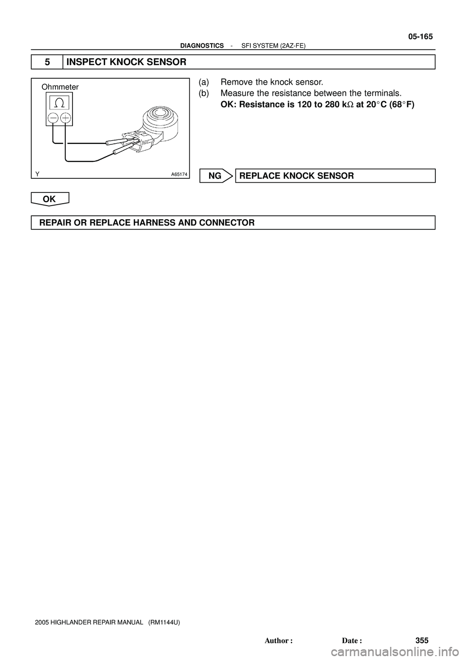
5 INSPECT KNOCK SENSOR
(a) Remove the knock sensor.
(b) Measure the resistance between the terminals.
OK: Resistance is 120 to 280 kW at 20�C (68�F)
NG REPLACE KNOCK SENSOR
OK
REPAIR OR REPLACE HARNESS AND CONNECTOR