Page 1817 of 1897
SR0EH-06
F08837
Floor shift:
8.8 (90, 78 in.´lbf)
50 (510, 37)
Torx ScrewSteering Wheel Pad
Steering Wheel Lower
No. 2 Cover
Combination Switch
(w/ Spiral cable)
Column Upper Cover
Column Lower CoverSteering Wheel Lower
No. 2 CoverSteering Wheel
Steering Column
Assembly
Clamp
Intermediate Shaft
Sub-assembly
25 (260, 19)
N´m (kgf´cm, ft´lbf): Specified torqueTorx Screw
Lower Instrument Finish
Panel Assembly
Return Spring
No. 2 Column Hole
Cover Sub-assemblyUniversal Joint Assembly No. 2 Column Lower CoverSteering Angle
Sensor
Lower No. 1 Instrument
Panel Sub-assembly
Lower LH Instrument Panel
Insert Sub-assembly
No. 2 Heater to Register Duct
Air Cleaner Assembly
with Air Cleaner Hose
Steering Angle
Sensor Adapter Speed Control Main
Switch Assemblyw/ VSC:
w/ VSC:
8.8 (90, 78 in.´lbf)
35 (360, 26)
35 (360, 26)
35 (360, 26)
Hood Lock Release Lever
- STEERINGTILT STEERING COLUMN
SR-9
1472
2001 AVALON (RM808U)
TILT STEERING COLUMN
COMPONENTS
Page 1818 of 1897
F08849
Column shift:
50 (510, 37)
8.8 (90, 78 in.´lbf)
Torx ScrewSteering Wheel Pad
Steering Wheel Lower
No. 2 Cover
Combination Switch
(w/ Spiral cable)
Column Upper Cover
Column Lower CoverSteering Wheel Lower
No. 2 Cover Steering Wheel
Steering Column
Assembly
Clamp
Intermediate Shaft
Sub-assembly
25 (260, 19)
35 (360, 26)
N´m (kgf´cm, ft´lbf) : Specified torqueTorx Screw
Lower Instrument Finish
Panel Assembly
Return Spring
No. 2 Column Hole
Cover Sub-assembly
Universal Joint Assembly No. 2 Column Lower CoverSteering
Angle Sensor
Lower No. 1 Instrument
Panel Sub-assembly
Lower LH Instrument Panel
Insert Sub-assembly
No. 2 Heater to Register Duct
Air Cleaner Assembly
with Air Cleaner Hose
Steering Angle
Sensor Adapter Speed Control Main
Switch Assembly
Transmission Control
Cable
w/ VSC:
w/ VSC:
Hood Lock Release Lever
35 (360, 26)
35 (360, 26)
8.8 (90, 78 in.´lbf)
SR-10
- STEERINGTILT STEERING COLUMN
1473 Author�: Date�:
2001 AVALON (RM808U)
Page 1824 of 1897

INSTALLATION
1. INSTALL SPEED CONTROL MAIN SWITCH AS-
SEMBLY")
SR0Z8-02
F08848
Guide
Projection
F08831
Matchmarks
F08834
SR-22
- STEERINGTILT STEERING COLUMN
1485 Author�: Date�:
2001 AVALON (RM808U)
INSTALLATION
1. INSTALL SPEED CONTROL MAIN SWITCH AS-
SEMBLY TO STEERING WHEEL
Install the speed control main switch assembly with the 2
screws to the steering wheel.
2. w/ VSC:
INSTALL STEERING ANGLE SENSOR ADAPTER AND
STEERING ANGLE SENSOR
(a) Fit a projection of the steering angle sensor adapter into
a hole in the steering column shaft.
(b) Set a projection of the steering angle sensor in the guide
of the steering column and fix the steering angle sensor.
3. INSTALL UNIVERSAL JOINT ASSEMBLY
(a) Align the matchmarks on the universal joint assembly and
main shaft assembly.
(b) Install the bolt.
Torque: 35 N´m (360 kgf´cm, 26 ft´lbf)
4. INSTALL NO. 2 COLUMN HOLE COVER SUB- AS-
SEMBLY AND INTERMEDIATE SHAFT SUB- AS-
SEMBLY
(a) Install the No. 2 column hole cover sub-assembly.
(b) Temporarily install the intermediate shaft sub-assembly
with the bolt A.
5. INSTALL STEERING COLUMN ASSEMBLY
(a) Install the steering column assembly with the 4 nuts.
Torque: 25 N´m (260 kgf´cm, 19 ft´lbf)
(b) Connect the connectors.
(c) Install the nut and return spring.
6. Column shift:
CONNECT TRANSMISSION CONTROL CABLE
(a) Connect the transmission control cable to the cable
bracket of the column tube.
(b) Connect the transmission control cable to the shift lever
housing.
Page 1826 of 1897

15. INSTALL LOWER NO. 1 INSTRUMENT PANEL SUB-
ASSEMBLY
(a) Connect the connec")
F03856Marks
F08828
Torx ScrewScrew Case
SR-24
- STEERINGTILT STEERING COLUMN
1487 Author�: Date�:
2001 AVALON (RM808U)
15. INSTALL LOWER NO. 1 INSTRUMENT PANEL SUB-
ASSEMBLY
(a) Connect the connectors and install the lower No. 1 instru-
ment panel sub-assembly.
(b) Install the 2 screws.
(c) Connect the hood lock release lever with the 2 screws.
16. CENTER SPIRAL CABLE
(a) Check that the front wheels are facing straight ahead.
(b) Turn the spiral cable counterclockwise by hand until it be-
comes harder to turn.
(c) Then rotate the spiral cable clockwise about 2.5 turns to
align the marks.
HINT:
The spiral cable will rotate about 2.5 turns to either left or right
of the center.
17. INSTALL STEERING WHEEL
(a) Align the matchmarks on the steering wheel and main
shaft assembly.
(b) Install the steering wheel set nut.
Torque: 50 N´m (510 kgf´cm, 37 ft´lbf)
(c) Connect the connector.
18. INSTALL STEERING WHEEL PAD
NOTICE:
�Never use airbag parts from another vehicle. When
replacing parts, replace with new ones.
�Make sure the wheel pad is installed to the specified
torque.
�If the wheel pad has been dropped, or there are
cracks, dents or other defects on the case or connec-
tor, replace the wheel pad with a new one.
�When installing the wheel pad, take care that the wir-
ings do not interfere with other parts and are not
pinched between other parts.
(a) Connect the airbag connector.
(b) Install the steering wheel pad after confirming that the cir-
cumference groove of the torx screws is caught on the
screw case.
(c) Using a torx socket wrench, install the 2 screws.
Torque: 8.8 N´m (90 kgf´cm, 78 in.´lbf)
(d) Install the 2 steering wheel lower No. 2 covers.
19. CHECK STEERING WHEEL CENTER POINT
20. w/ VSC:
PERFORM STEERING ANGLE SENSOR ZERO POINT
CALIBRATION (See page DI-252)
Page 1837 of 1897

REMOVAL
1. REMOVE FRONT WHEEL
Torque: 103 N´m (1,050 kgf´cm, 76 ft´lbf)
2. CHECK")
SA0VS-02
W03084
W03093
W03139
- SUSPENSION AND AXLEFRONT AXLE HUB
SA-9
1343 Author�: Date�:
2001 AVALON (RM808U)
REMOVAL
1. REMOVE FRONT WHEEL
Torque: 103 N´m (1,050 kgf´cm, 76 ft´lbf)
2. CHECK BEARING BACKLASH AND AXLE HUB DEVI-
ATION
(a) Remove the 2 bolts, brake caliper and disc.
(b) Support the brake caliper securely.
(c) Using a dial indicator, check the backlash near the center
of the axle hub.
Maximum: 0.05 mm (0.0020 in.)
If the backlash exceeds the maximum, replace the bearing.
(d) Using a dial indicator, check the deviation at the surface
of the axle hub outside the hub bolt.
Maximum: 0.05 mm (0.0020 in.)
If the deviation exceeds the maximum, replace the axle hub.
(e) Install the disc, brake caliper and 2 bolts.
Torque: 107 N´m (1,090 kgf´cm, 79 ft´lbf)
3. REMOVE DRIVE SHAFT LOCK NUT
(a) Remove the cotter pin and lock cap.
(b) While applying the brakes, remove the nut.
Torque: 294 N´m (3,000 kgf´cm, 217 ft´lbf)
(c) Remove the 2 bolts, brake caliper and disc.
(d) Support the brake caliper securely.
4. DISCONNECT ABS SPEED SENSOR AND WIRE HAR-
NESS CLAMP
Remove the bolt and disconnect the ABS speed sensor and
wire harness clamp.
Torque: 8.0 N´m (82 kgf´cm, 71 in.´lbf)
5. LOOSEN 2 NUTS ON LOWER SIDE OF SHOCK AB-
SORBER
HINT:
Do not remove the bolts.
Torque: 211 N´m (2,150 kgf´cm, 156 ft´lbf)
HINT:
At the this time of installation, coat the nut's thread with engine
oil.
Page 1847 of 1897

REMOVAL
NOTICE:
�The hub bearing could be damaged if it is subjected
t")
SA0VY-02
FA1535
SST
W03093
W03142
F07389
SA-16
- SUSPENSION AND AXLEFRONT DRIVE SHAFT
1350 Author�: Date�:
2001 AVALON (RM808U)
REMOVAL
NOTICE:
�The hub bearing could be damaged if it is subjected
to the vehicle weight, such as when moving the ve-
hicle with the drive shaft removed.
Therefore, if it is absolutely necessary to place the ve-
hicle weight on the hub bearing, first support it with
SST.
SST 09608-16042 (09608-02021, 09608-02041)
�After disconnecting the drive shaft from the axle hub,
work carefully so as not to damage the ABS speed
sensor rotor serration on the drive shaft.
1. REMOVE FRONT WHEEL
Torque: 103 N´m (1,050 kgf´cm, 76 ft´lbf)
2. REMOVE FRONT FENDER APRON SEAL
3. DRAIN ATF
4. REMOVE DRIVE SHAFT LOCK NUT
(a) Remove the cotter pin and lock cap.
(b) While applying brakes, remove the nut.
Torque: 294 N´m (3,000 kgf´cm, 217 ft´lbf)
5. DISCONNECT TIE ROD END FROM STEERING
KNUCKLE (See page SA-9)
6. DISCONNECT LOWER SUSPENSION ARM FROM
LOWER BALL JOINT (See page SA-9)
7. DISCONNECT DRIVE SHAFT FROM AXLE HUB
Using a plastic hammer, disconnect the drive shaft from the axle
hub.
NOTICE:
Be careful not to damage the boot and ABS speed sensor
rotor.
8. LH drive shaft:
REMOVE DRIVE SHAFT
(a) Using a hub nut wrench and hammer handle or an equiva-
lent, remove the drive shaft.
NOTICE:
Be careful not to damage the dust cover and oil seal.
Page 1851 of 1897
SA0VD-03
R08850
R08861SSTSST
- SUSPENSION AND AXLEFRONT LOWER BALL JOINT
SA-39
1373 Author�: Date�:
2001 AVALON (RM808U)
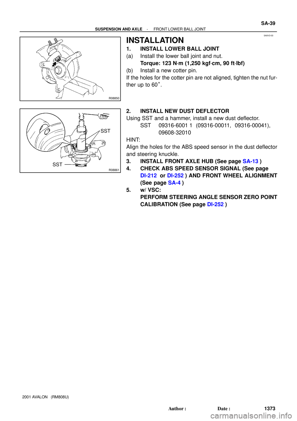
INSTALLATION
1. INSTALL LOWER BALL JOINT
(a) Install the lower ball joint and nut.
Torque: 123 N´m (1,250 kgf´cm, 90 ft´lbf)
(b) Install a new cotter pin.
If the holes for the cotter pin are not aligned, tighten the nut fur-
ther up to 60°.
2. INSTALL NEW DUST DEFLECTOR
Using SST and a hammer, install a new dust deflector.
SST 09316-6001 1 (09316-00011, 09316-00041),
09608-32010
HINT:
Align the holes for the ABS speed sensor in the dust deflector
and steering knuckle.
3. INSTALL FRONT AXLE HUB (See page SA-13)
4. CHECK ABS SPEED SENSOR SIGNAL (See page
DI-212 or DI-252) AND FRONT WHEEL ALIGNMENT
(See page SA-4)
5. w/ VSC:
PERFORM STEERING ANGLE SENSOR ZERO POINT
CALIBRATION (See page DI-252)
Page 1855 of 1897
SA0V7-02
F02225
F02226
F02227
- SUSPENSION AND AXLEFRONT LOWER SUSPENSION ARM
SA-33
1367 Author�: Date�:
2001 AVALON (RM808U)
REMOVAL
1. REMOVE FRONT WHEEL
Torque: 103 N´m (1,050 kgf´cm, 76 ft´lbf)
2. DISCONNECT LOWER SUSPENSION ARM FROM
LOWER BALL JOINT
Remove the 2 nuts and bolt, and disconnect the lower suspen-
sion arm from the lower ball joint.
Torque: 127 N´m (1,300 kgf´cm, 94 ft´lbf)
3. REMOVE LOWER SUSPENSION ARM
(a) Remove the 2 bolts on the front side of the lower suspen-
sion arm.
Torque: 206 N´m (2,100 kgf´cm, 152 ft´lbf)
(b) Remove the bolt and nut on the rear side of the lower sus-
pension arm.
Torque: 206 N´m (2,100 kgf´cm, 152 ft´lbf)
(c) Remove the lower suspension arm.
(d) Remove the lower suspension arm bushing stopper from
the lower suspension arm.

50 (510, 37)
Torx ScrewSteering Wheel Pad
Steering Wheel Lower
No. 2 Cover
Combination Switch
(w/ Spiral cable)
Column Upper Cover
Column Lower Cover")

8.8 (90, 78 in.´lbf)
Torx ScrewSteering Wheel Pad
Steering Wheel Lower
No. 2 Cover
Combination Switch
(w/ Spiral cable)
Column Upper Cover
Column Lower CoverSteering")