Page 1046 of 1897
DI-12
- DIAGNOSTICSENGINE
168 Author�: Date�:
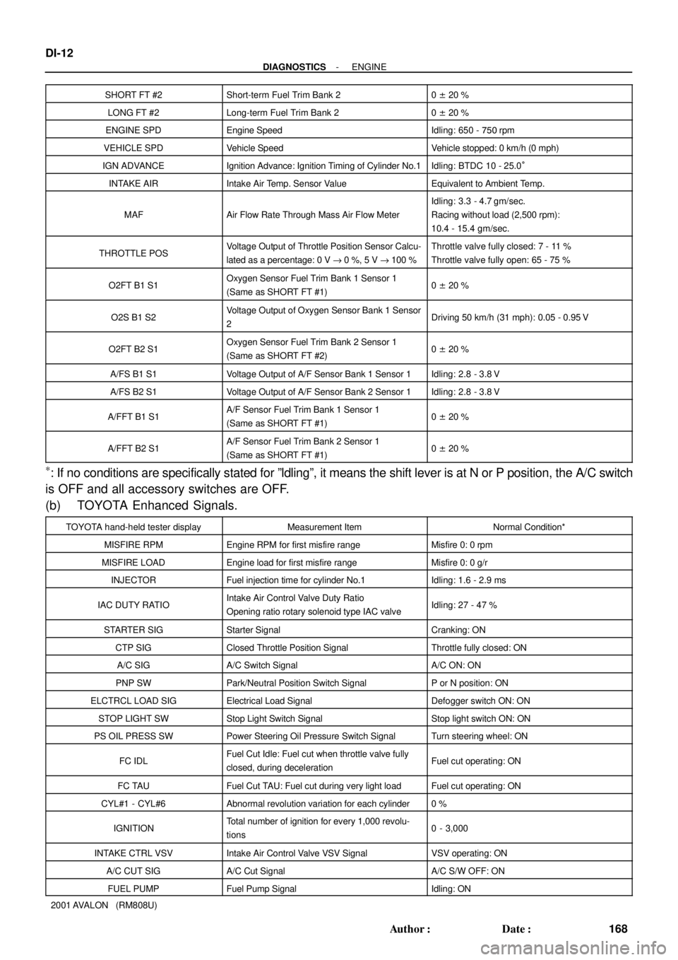
2001 AVALON (RM808U)SHORT FT #2
Short-term Fuel Trim Bank 20 ± 20 %
LONG FT #2Long-term Fuel Trim Bank 20 ± 20 %
ENGINE SPDEngine SpeedIdling: 650 - 750 rpm
VEHICLE SPDVehicle SpeedVehicle stopped: 0 km/h (0 mph)
IGN ADVANCEIgnition Advance: Ignition Timing of Cylinder No.1Idling: BTDC 10 - 25.0°
INTAKE AIRIntake Air Temp. Sensor ValueEquivalent to Ambient Temp.
MAFAir Flow Rate Through Mass Air Flow Meter
Idling: 3.3 - 4.7 gm/sec.
Racing without load (2,500 rpm):
10.4 - 15.4 gm/sec.
THROTTLE POSVoltage Output of Throttle Position Sensor Calcu-
lated as a percentage: 0 V "0 %, 5 V "100 %Throttle valve fully closed: 7 - 11 %
Throttle valve fully open: 65 - 75 %
O2FT B1 S1Oxygen Sensor Fuel Trim Bank 1 Sensor 1
(Same as SHORT FT #1)0 ± 20 %
O2S B1 S2Voltage Output of Oxygen Sensor Bank 1 Sensor
2Driving 50 km/h (31 mph): 0.05 - 0.95 V
O2FT B2 S1Oxygen Sensor Fuel Trim Bank 2 Sensor 1
(Same as SHORT FT #2)0 ± 20 %
A/FS B1 S1Voltage Output of A/F Sensor Bank 1 Sensor 1Idling: 2.8 - 3.8 V
A/FS B2 S1Voltage Output of A/F Sensor Bank 2 Sensor 1Idling: 2.8 - 3.8 V
A/FFT B1 S1A/F Sensor Fuel Trim Bank 1 Sensor 1
(Same as SHORT FT #1)0 ± 20 %
A/FFT B2 S1A/F Sensor Fuel Trim Bank 2 Sensor 1
(Same as SHORT FT #1)0 ± 20 %
*: If no conditions are specifically stated for ºldlingº, it means the shift lever is at N or P position, the A/C switch
is OFF and all accessory switches are OFF.
(b) TOYOTA Enhanced Signals.
TOYOTA hand-held tester displayMeasurement ItemNormal Condition*
MISFIRE RPMEngine RPM for first misfire rangeMisfire 0: 0 rpm
MISFIRE LOADEngine load for first misfire rangeMisfire 0: 0 g/r
INJECTORFuel injection time for cylinder No.1Idling: 1.6 - 2.9 ms
IAC DUTY RATIOIntake Air Control Valve Duty Ratio
Opening ratio rotary solenoid type IAC valveIdling: 27 - 47 %
STARTER SIGStarter SignalCranking: ON
CTP SIGClosed Throttle Position SignalThrottle fully closed: ON
A/C SIGA/C Switch SignalA/C ON: ON
PNP SWPark/Neutral Position Switch SignalP or N position: ON
ELCTRCL LOAD SIGElectrical Load SignalDefogger switch ON: ON
STOP LIGHT SWStop Light Switch SignalStop light switch ON: ON
PS OIL PRESS SWPower Steering Oil Pressure Switch SignalTurn steering wheel: ON
FC IDLFuel Cut Idle: Fuel cut when throttle valve fully
closed, during decelerationFuel cut operating: ON
FC TAUFuel Cut TAU: Fuel cut during very light loadFuel cut operating: ON
CYL#1 - CYL#6Abnormal revolution variation for each cylinder0 %
IGNITIONTotal number of ignition for every 1,000 revolu-
tions0 - 3,000
INTAKE CTRL VSVIntake Air Control Valve VSV SignalVSV operating: ON
A/C CUT SIGA/C Cut SignalA/C S/W OFF: ON
FUEL PUMPFuel Pump SignalIdling: ON
Page 1276 of 1897
B08625AirDisconnect
Air Inlet
Line Hose
B01253
Pinch
Push
AA
Pinch
B08620
B08621
Purge Port
Vent Port
Cap EVAP Port
Air Drain Port
Air
- EMISSION CONTROLEVAPORATIVE EMISSION (EVAP) CONTROL SYSTEM
EC-9
1103 Author�: Date�:
2001 AVALON (RM808U)
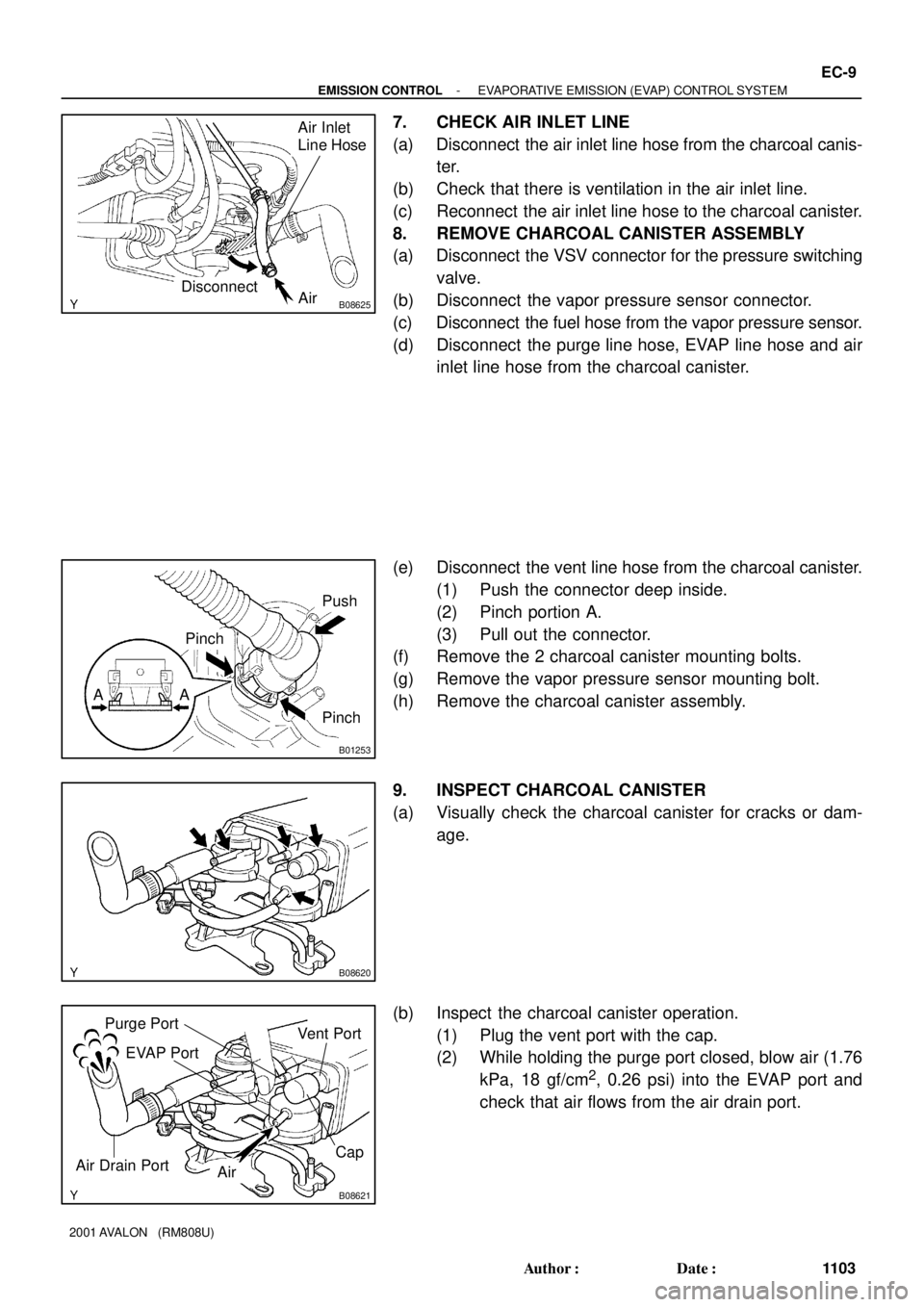
7. CHECK AIR INLET LINE
(a) Disconnect the air inlet line hose from the charcoal canis-
ter.
(b) Check that there is ventilation in the air inlet line.
(c) Reconnect the air inlet line hose to the charcoal canister.
8. REMOVE CHARCOAL CANISTER ASSEMBLY
(a) Disconnect the VSV connector for the pressure switching
valve.
(b) Disconnect the vapor pressure sensor connector.
(c) Disconnect the fuel hose from the vapor pressure sensor.
(d) Disconnect the purge line hose, EVAP line hose and air
inlet line hose from the charcoal canister.
(e) Disconnect the vent line hose from the charcoal canister.
(1) Push the connector deep inside.
(2) Pinch portion A.
(3) Pull out the connector.
(f) Remove the 2 charcoal canister mounting bolts.
(g) Remove the vapor pressure sensor mounting bolt.
(h) Remove the charcoal canister assembly.
9. INSPECT CHARCOAL CANISTER
(a) Visually check the charcoal canister for cracks or dam-
age.
(b) Inspect the charcoal canister operation.
(1) Plug the vent port with the cap.
(2) While holding the purge port closed, blow air (1.76
kPa, 18 gf/cm
2, 0.26 psi) into the EVAP port and
check that air flows from the air drain port.
Page 1440 of 1897
IN04Q-08
- INTRODUCTIONTERMS
IN-35
35 Author�: Date�:
2001 AVALON (RM808U)
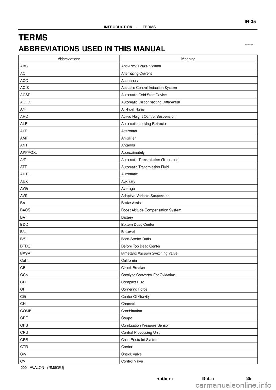
TERMS
ABBREVIATIONS USED IN THIS MANUAL
AbbreviationsMeaning
ABSAnti-Lock Brake System
ACAlternating Current
ACCAccessory
ACISAcoustic Control Induction System
ACSDAutomatic Cold Start Device
A.D.D.Automatic Disconnecting Differential
A/FAir-Fuel Ratio
AHCActive Height Control Suspension
ALRAutomatic Locking Retractor
ALTAlternator
AMPAmplifier
ANTAntenna
APPROX.Approximately
A/TAutomatic Transmission (Transaxle)
AT FAutomatic Transmission Fluid
AUTOAutomatic
AUXAuxiliary
AV GAverage
AV SAdaptive Variable Suspension
BABrake Assist
BACSBoost Altitude Compensation System
BATBattery
BDCBottom Dead Center
B/LBi-Level
B/SBore-Stroke Ratio
BTDCBefore Top Dead Center
BVSVBimetallic Vacuum Switching Valve
Calif.California
CBCircuit Breaker
CCoCatalytic Converter For Oxidation
CDCompact Disc
CFCornering Force
CGCenter Of Gravity
CHChannel
COMB.Combination
CPECoupe
CPSCombustion Pressure Sensor
CPUCentral Processing Unit
CRSChild Restraint System
CTRCenter
C/VCheck Valve
CVControl Valve
Page 1595 of 1897
SF103-01
B06683
A/F Sensor Connector A/F Sensor
N´m (kgf´cm, ft´lbf) : Specified torque Bank 1 Sensor 1
44 (450, 32)
B06681
A/F Sensor Connector
A/F Sensor
N´m (kgf´cm, ft´lbf) : Specified torque Bank 2 Sensor 1
44 (450, 32)
LH Exhaust Manifold
Heat Insulator
SF-78
- SFIAIR-FUEL RATIO (A/F) SENSOR
1187 Author�: Date�:
2001 AVALON (RM808U)
AIR-FUEL RATIO (A/F) SENSOR
COMPONENTS
Page 1596 of 1897
B06682
Bank 1 Sensor 1
Bank 2 Sensor 1
Ohmmeter +B
HT
+BHT Ohmmeter
SF104-01
- SFIAIR-FUEL RATIO (A/F) SENSOR
SF-79
1188 Author�: Date�:
2001 AVALON (RM808U)
INSPECTION
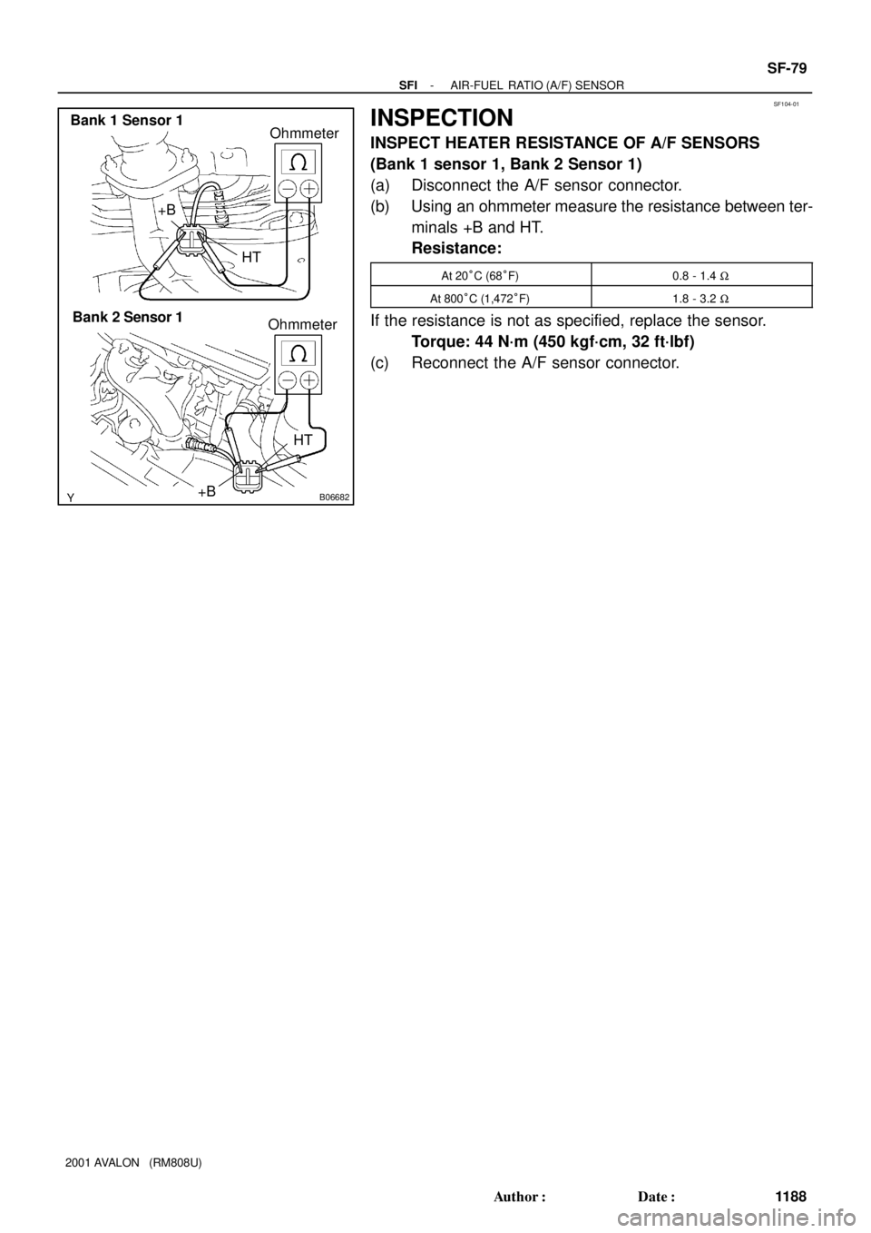
INSPECT HEATER RESISTANCE OF A/F SENSORS
(Bank 1 sensor 1, Bank 2 Sensor 1)
(a) Disconnect the A/F sensor connector.
(b) Using an ohmmeter measure the resistance between ter-
minals +B and HT.
Resistance:
At 20°C (68°F)0.8 - 1.4 W
At 800°C (1,472°F)1.8 - 3.2 W
If the resistance is not as specified, replace the sensor.
Torque: 44 N´m (450 kgf´cm, 32 ft´lbf)
(c) Reconnect the A/F sensor connector.
Page 1646 of 1897
SF0LC-03
- SFISFI SYSTEM
SF-1
111 0 Author�: Date�:
2001 AVALON (RM808U)
SFI SYSTEM
PRECAUTION
1. BEFORE WORKING ON FUEL SYSTEM, DISCON-
NECT NEGATIVE (-) TERMINAL CABLE FROM BAT-
TERY
HINT:
Any diagnostic trouble code retained by the computer will be
erased when the negative (-) terminal cable is removed from
the battery.
Therefore, if necessary, read the diagnosis before removing the
negative (-) terminal cable from the battery.
2. DO NOT SMOKE OR WORK NEAR AN OPEN FLAME
WHEN WORKING ON FUEL SYSTEM
3. KEEP GASOLINE AWAY FROM RUBBER OR LEATH-
ER PARTS
4. MAINTENANCE PRECAUTIONS
(a) In event of engine misfire, these precautions should be
taken.
(1) Check proper connection to battery terminals, etc.
(2) After repair work, check that the ignition coil termi-
nals and all other ignition system lines are recon-
nected securely.
(3) When cleaning the engine compartment, be espe-
cially careful to protect the electrical system from
water.
(b) Precautions when handling the oxygen sensor.
(1) Do not allow oxygen sensor to drop or hit against an
object.
(2) Do not allow the sensor to come into contact with
water.
5. IF VEHICLE IS EQUIPPED WITH A MOBILE RADIO
SYSTEM (HAM, CB, ETC.)
If the vehicle is equipped with a mobile communication system,
refer to the precaution in the IN section.
6. AIR INDUCTION SYSTEM
(a) Separation of the engine oil dipstick, oil filler cap, PCV
hose, etc. may cause the engine to run out of tune.
(b) Disconnection, looseness or cracks in the parts of the air
induction system between the throttle body and cylinder
head will allow air suction and cause the engine to run out
of tune.
7. ELECTRONIC CONTROL SYSTEM
(a) Before removing SFI wiring connectors, terminals, etc.,
first disconnect the power by either turning the ignition
switch to LOCK or disconnecting the negative (-) terminal
cable from the battery.
HINT:
Always check the diagnostic trouble code before disconnecting
the negative (-) terminal cable from the battery.