Page 1079 of 1897
I13625
RCL-
RCL+
SLD-
SLD+
LFT+
LFT- FRV-
FRV+ W-BGND
2 17Power Seat ECU
12
21
2
1 21
W-B
W-BCCJ14
J/C
11
A
J11
J/CP20
P20
P20
P20
P20
P20
P20
P20
P20 BK BC1P24 Power Seat Motor
Reclining Control
P22 Power Seat Motor
Front Vertical Control
P25 Power Seat Motor
Slide Control
P23 Power Seat Motor
Rear Vertial ControlR-B
R-W
L-W
L-R
L-B
L
L-Y
R9
10
3
4
6
5 DI-500
- DIAGNOSTICSPOWER SEAT CONTROL SYSTEM (w/ Driving Position
Memory)
656 Author�: Date�:
2001 AVALON (RM808U)
Motor Circuit
CIRCUIT DESCRIPTION
The Seat Position Control ECU controls the 4 motors for slide, front vertical, rear vertical and reclining.
WIRING DIAGRAM
DI0G4-08
Page 1080 of 1897
N21468
Slide Motor
21
21
- DIAGNOSTICSPOWER SEAT CONTROL SYSTEM (w/ Driving Position
Memory)DI-501
657 Author�: Date�:
2001 AVALON (RM808U)
INSPECTION PROCEDURE
1 Check motor.
PREPARATION:
(a) Remove seat.
(b) Disconnect each motor connector.
CHECK:
Check seat movement when battery positive voltage is applied
to each motor.
Slide Motor
CHECK:
Connect battery � to terminal 2 and battery � to terminal 1 of
the slide motor connector.
OK:
The seat moves forward.
CHECK:
Connect battery � to terminal 2 and battery � to terminal 1 of
the slide motor connector.
OK:
The seat moves backward.
Page 1081 of 1897

658 Author�: Date�:
20")
N21467
N21465
N21466
I00528
Front Vertical Motor
Reclining Motor Rear Vertical Motor21
21
21
21
21
21
DI-502- DIAGNOSTICSPOWER SEAT CONTROL SYSTEM (w/ Driving Position
Memory)
658 Author�: Date�:
2001 AVALON (RM808U)
Front Vertical Motor
CHECK:
Connect battery � to terminal 2 and battery � to terminal 1 of
the front vertical motor connector.
OK:
The front of the seat cushion rises.
CHECK:
Connect battery � to terminal 2 and battery � to terminal 1 of
the front vertical motor connector.
OK:
The front of the seat cushion lowers.
Rear Vertical Motor
CHECK:
Connect battery � to terminal 2 and battery � to terminal 1 of
the rear vertical motor connector.
OK:
The front of the seat cushion rises.
CHECK:
Connect battery � to terminal 2 and battery � to terminal 1 of
the rear vertical motor connector.
OK:
The front of the seat cushion lowers.
Reclining Motor
CHECK:
Connect battery � to terminal 2 and battery � to terminal 1 of
the reclining motor connector.
OK:
The seat back returns to up right.
CHECK:
Connect battery � to terminal 2 and battery � to terminal 1 of
the reclining motor connector.
OK:
The seat back is reclining.
NG Replace motor.
OK
Page 1082 of 1897
- DIAGNOSTICSPOWER SEAT CONTROL SYSTEM (w/ Driving Position
Memory)DI-503
659 Author�: Date�:
2001 AVALON (RM808U)
2 Check harness and connector between Seat Position Control ECU and motor
(See page DI-489).
NG Repair or replace harness or connector.
OK
Proceed to next circuit inspection shown on
problem symptom table (See page DI-493).
Page 1083 of 1897
8 V
0 V
ECU
N14754
Example: Slide Motor
Motor Sensor
(+)
2
(+) (-)
(-)1 31 2
DI-506- DIAGNOSTICSPOWER SEAT CONTROL SYSTEM (w/ Driv")
BE3991
1 pulse output per one
turn of motor
Position Sensor
(in Motor)8 V
0 V
ECU
N14754
Example: Slide Motor
Motor Sensor
(+)
2
(+) (-)
(-)1 31 2
DI-506- DIAGNOSTICSPOWER SEAT CONTROL SYSTEM (w/ Driving Position
Memory)
662 Author�: Date�:
2001 AVALON (RM808U)
Position Sensor Circuit
CIRCUIT DESCRIPTION
The position sensor senses movement of the seat and send
pulse signals to the ECU. The position sensor sends pulse to
the ECU in proportion to the amount of seat movement, as
shown in the diagram on the left.
The ECU uses the number of pulses to constantly calculate the
position relative to the memory position and returns the seat to
the memorized position.
If a malfunction occurs in a position sensor and a sensor signal
is not input to the ECU even when the motor operates, the ECU
prohibits return operation.
WIRING DIAGRAM
See page DI-504.
INSPECTION PROCEDURE
1 Check position sensor.
PREPARATION:
Disconnect the connector of the sensor and the connector of
the motor leading to the sensor.
CHECK:
(a) Connect positive � lead to terminal 3 of sensor and nega-
tive � lead to terminal 2.
(b) Measure voltage between terminal 1 of sensor and body
ground when battery positive voltage is applied between
terminals 1 and 2 of motor connector.
HINT:
When the battery positive voltage is applied to the motor con-
nector terminals, � and � are interchangeable.
OK:
ConditionVoltage
Motor stopped
(Check several times with the motor in a
different position each time.)0 V or battery positive voltage according
to stop position.
with motor turninghalf of battery positive voltage
NG Replace position sensor.
OK
DI0G9-08
Page 1084 of 1897
- DIAGNOSTICSPOWER SEAT CONTROL SYSTEM (w/ Driving Position
Memory)DI-507
663 Author�: Date�:
2001 AVALON (RM808U)
2 Check harness and connectors between Seat Position Control ECU and position
sensors (See page IN-30).
NG Repair or replace harness or connectors.
OK
Check and replace Seat Position Control
ECU.
Page 1085 of 1897
I13624
SSRR
PVCC
SSFV SSRS
SSRL L-BL
R
L-W53
4 16
17Power Seat ECU
1 2
1 2
1 2
1 2
3 3 3 3
BR
BR
BR B
BB B
BR J14
J/C
9
9
BR
BR A
AJ3
J/C
IHP21
P21
P21
P21
P21 L-R BR
P30
P29
P32
P31
Power Seat
Position Sensor
Reclining Control
Front Vertical Control
Rear Vertical Control Slide Control
IA1 BC1
BR
J/CJ14
A
A
A A R
R
R
R DI-504
- DIAGNOSTICSPOWER SEAT CONTROL SYSTEM (w/ Driving Position
Memory)
660 Author�: Date�:
2001 AVALON (RM808U)
Position Sensor Power Source Circuit
CIRCUIT DESCRIPTION
This circuit provides power to the slide, front vertical and reclining position sensors.
WIRING DIAGRAM
DI0G6-09
Page 1086 of 1897
I11593
(+) (-)
5 (PVCC)
- DIAGNOSTICSPOWER SEAT CONTROL SYSTEM (w/ Driving Position
Memory)DI-505
661 Author�: Date�:
2001 AVALON (RM808U)
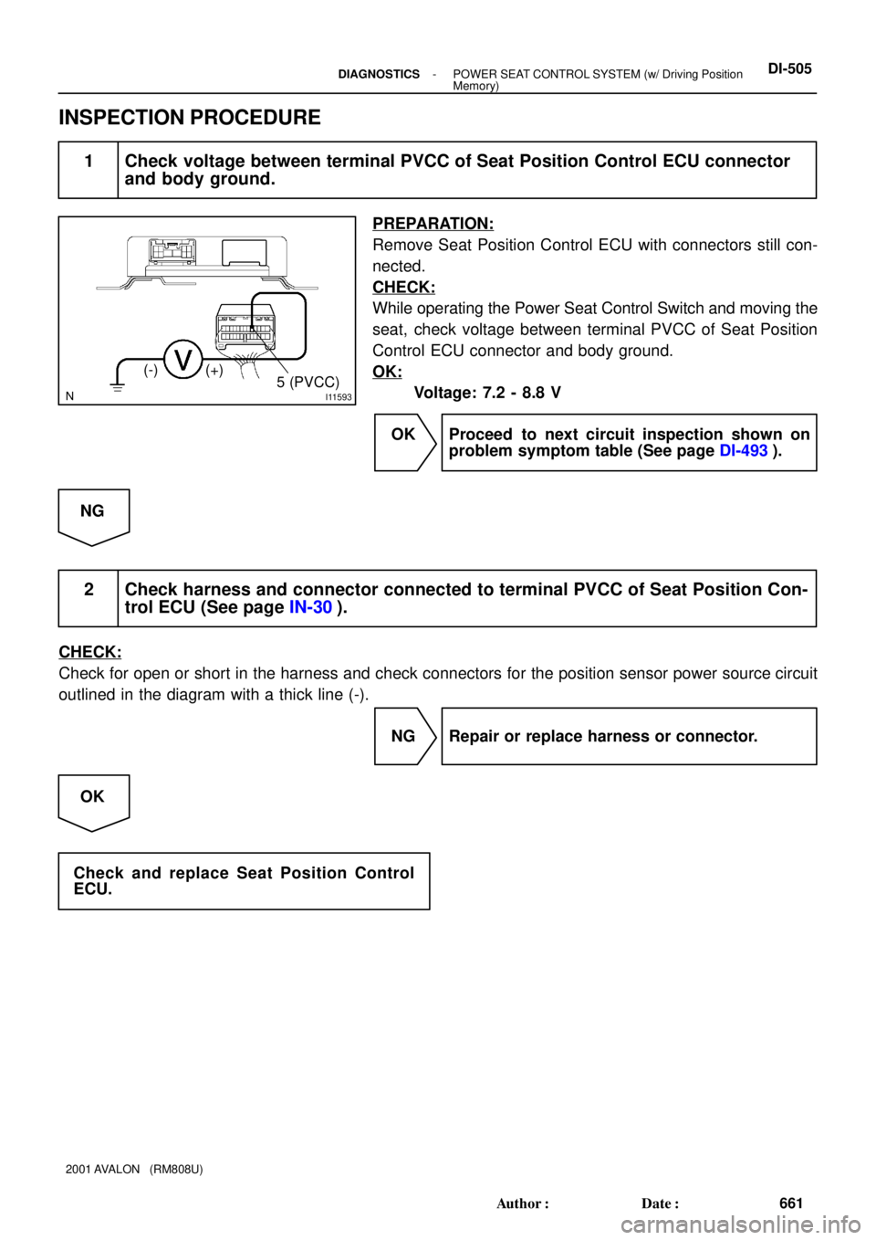
INSPECTION PROCEDURE
1 Check voltage between terminal PVCC of Seat Position Control ECU connector
and body ground.
PREPARATION:
Remove Seat Position Control ECU with connectors still con-
nected.
CHECK:
While operating the Power Seat Control Switch and moving the
seat, check voltage between terminal PVCC of Seat Position
Control ECU connector and body ground.
OK:
Voltage: 7.2 - 8.8 V
OK Proceed to next circuit inspection shown on
problem symptom table (See page DI-493).
NG
2 Check harness and connector connected to terminal PVCC of Seat Position Con-
trol ECU (See page IN-30).
CHECK:
Check for open or short in the harness and check connectors for the position sensor power source circuit
outlined in the diagram with a thick line (-).
NG Repair or replace harness or connector.
OK
Check and replace Seat Position Control
ECU.