Page 286 of 1897
BE0IR-03
I12538
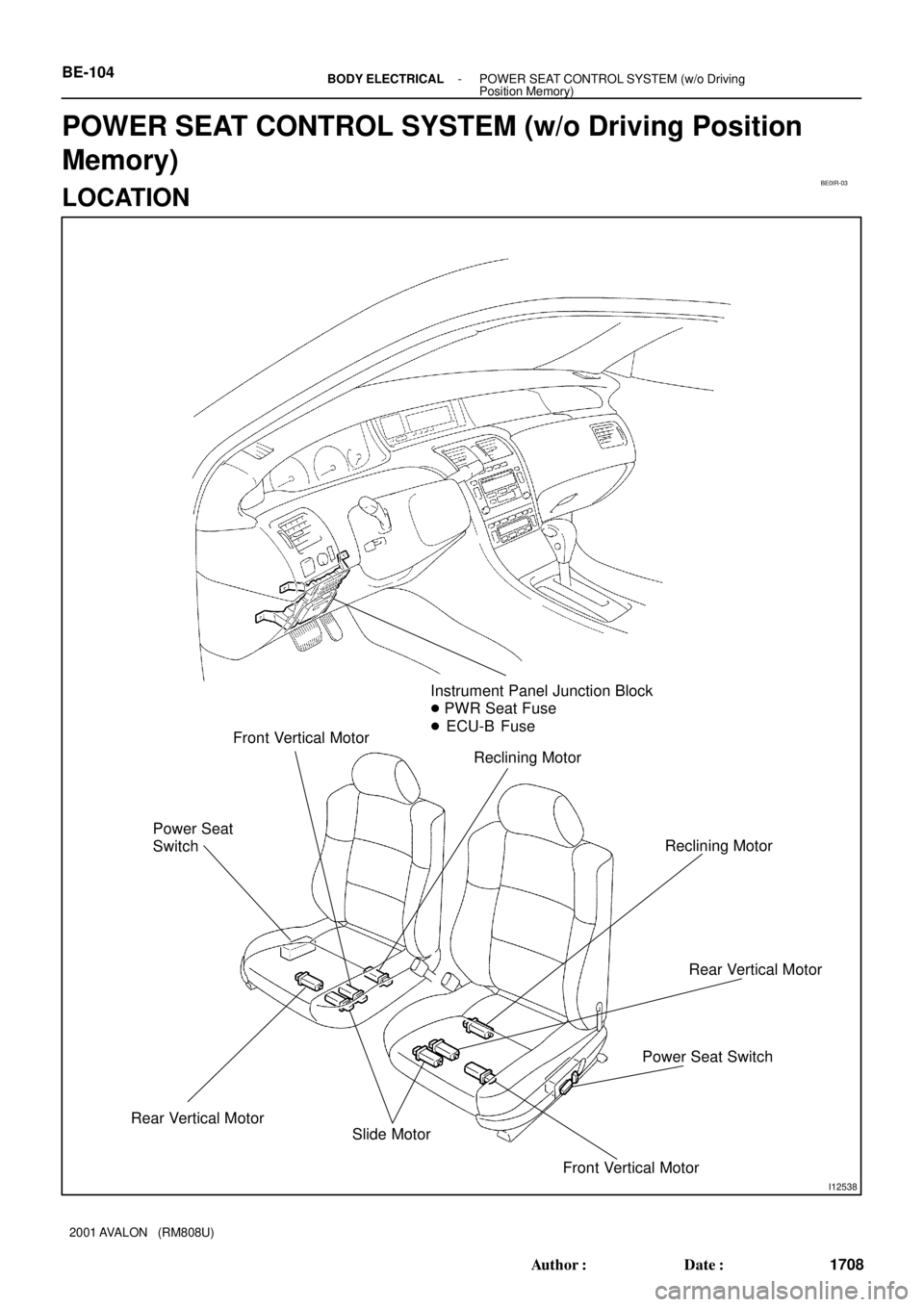
Instrument Panel Junction Block
� PWR Seat Fuse
� ECU-B Fuse
Reclining Motor Front Vertical Motor
Power Seat
Switch
Rear Vertical Motor
Reclining Motor
Power Seat SwitchRear Vertical Motor
Slide Motor
Front Vertical Motor BE-104
- BODY ELECTRICALPOWER SEAT CONTROL SYSTEM (w/o Driving
Position Memory)
1708 Author�: Date�:
2001 AVALON (RM808U)
POWER SEAT CONTROL SYSTEM (w/o Driving Position
Memory)
LOCATION
Page 311 of 1897

WIRELESS DOOR LOCK CONTROL SYSTEM
This system uses the multiplex communication system, so check diagnosis system of th")
- BODY ELECTRICALTROUBLESHOOTING
BE-7
1611 Author�: Date�:
2001 AVALON (RM808U)
WIRELESS DOOR LOCK CONTROL SYSTEM
This system uses the multiplex communication system, so check diagnosis system of the multiplex commu-
nication system before checking the body control system.
Some functions of wireless door lock control system do not operate.
HINT:
�Troubleshooting of the wireless door lock control system is based on the premise that the door lock
control system is operating normally. Accordingly, before troubleshooting the wireless door lock control
system, first make certain that the door lock control system is operating normally.
�If the trouble still reappears even though there are no abnormalities in any of the other circuits, then
check and replace the Wireless Door Lock Control Receiver as the last step.
SLIDING ROOF SYSTEM:
SymptomSuspect AreaSee page
Sliding roof system does not operate.
(Door Lock does not operate)1. SUN ROOF Fuse
2. GAUGE Fuse
3. Wire Harness-
-
-
Sliding roof system does not operate.
(Door Lock is normal)
1. Sliding Roof Control Switch
2. Sliding Roof Motor and Limit Switch
3. Sliding Roof Control Relay
4. Wire HarnessBE-103
BE-103
BE-103
-
Sliding roof system operates abnormally.
1. Sliding Roof Control Switch
2. Sliding Roof Motor and Limit Switch
3. Sliding Roof Control Relay
4. Wire HarnessBE-103
BE-103
BE-103
-
Sliding roof system stops operation half way.
(Stones of foreign material trapped in motor assembly)1. Sliding Roof Control Relay and Switch
2. Sliding Roof Motor and Limit Switch
3. Wire HarnessBE-103
BE-103
-
ºKey-of f Sliding Roofº operation does not operate.
1. DOOR Fuse
2. GAUGE Fuse
3. Ignition Switch
4. Body ECU
5. Wire Harness-
-
BE-16
BE-16
-
POWER SEAT CONTROL SYSTEM (w/o Driving position memory driver's seat):
SymptomSuspect AreaSee page
Power seat does not operate.
(Door lock system does not operate)1. DOOR Fuse
2. Wire Harness-
-
Power seat does not operate.
(Door lock system is normal)1. Power Seat Swtich (D,P)
2. Wire HarnessBE-105
-
ºSlide operationº does not operate.
1. Power Seat Switch (D, P)
2. Slide Motor (D, P)
3. Wire HarnessBE-16
BE-105
-
ºFront vertical Operationº does not operate.
1. Power Seat Switch (D, P)
2. Front Vertical Motor (D, P)
3. Wire HarnessBE-105
BE-105
-
ºRear verticalº does not operate.
1. Power Seat Switch
2. Rear Vertical Motor
3. Wire HarnessBE-105
BE-105
-
ºReclining Operationº does not operate.
1. Power Seat Switch (D, P)
2. Reclining Motor (D, P)
3. Wire HarnessBE-105
BE-105
-
(D): Driver's Seat
(P): Passenger's Seat
Page 362 of 1897
BO2Q2-01
H12211
� Hog Ring Separate type:
Seatback Cover
� Hog Ring
Seatback Frame
w/ Lumbar support:
Lumbar Support Assembly
Reclining Adjuster
Inside Cover
Seat Track
Cover
Sliding Motor Seat Track Cover
Front Power
Adjuster ShieldSeatback Pad
Headrest Support
Headrest
Seatback Board
Seat Cushion
Frame
Seat Wire
w/ Power seat control:
Power Seat Position
Control Computer
Seat Cushion
CoverSeat Cushion
Pad
Seat Cushion
Inner Shield
Front Seat Inner Belt
w/ Lumbar support:
Lumbar Support Switch Power Seat Switch
Slide Motor
w/ 4 way-vertical:
Front Vertical Motor
w/ Power seat control:
Seat Memory SwitchSeat Cushion
Shield
Power Seat
Switch Knob
Rear Vertical Motor
N´m (kgf´cm, ft´lbf): Specified torque
� Non-reusable part
18 (185, 13)
43 (440, 32)
37 (375, 27)
37 (375, 27)
37 (375, 27)
41 (420, 30)
- BODYFRONT SEAT (Power Adjuster Type)
BO-103
1888 Author�: Date�:
2001 AVALON (RM808U)
FRONT SEAT (Power Adjuster Type)
COMPONENTS
Page 363 of 1897
H12210
Bench type:
Headrest SupportHeadrest
Seatback Board
Seatback Frame
Seatback Pad
Seatback Cover
Seat Cushion Cover Seat
Cushion
PadSeat Wire
w/ Power seat control:
Power Seat Position Control Computer
Reclining Adjuster
Inside Cover
Seat Track Cover
Center Armrest� Hog Ring
� Hog Ring
Seat
Cushion
Frame
Seat Cushion Inner Shield
Seat Track Cover
Slide Motor
w/ 4 way-vertical:
Front Vertical Motor
w/ Power seat control:
Seat Memory Switch
37 (375, 27)
Reclining
Motor
Power Seat Switch
37 (375, 27)Front Seat
Inner Belt
Front Power
Adjuster Shield
Rear
Vertical Motor
Power Seat
Switch Knob
Seat
Cushion
Shield
N´m (kgf´cm, ft´lbf): Specified torque
� Non-reusable part
18 (185, 13)
18 (185, 13)
18 (185, 13)
43 (440, 32)
41 (420, 30)
Seat Track Cover
43 (440, 32)
37 (375, 27)
41 (420, 30)
41 (420, 30)
BO-104
- BODYFRONT SEAT (Power Adjuster Type)
1889 Author�: Date�:
2001 AVALON (RM808U)
Page 364 of 1897

1891 Author�: Date�:
2001 AVALON (RM808U)
DISASSEMBLY
CAUTION:
�When storing the seatback frame with the side airbag
asse")
BO2Q4-01
H12693A
H12203
H12204
BO-106
- BODYFRONT SEAT (Power Adjuster Type)
1891 Author�: Date�:
2001 AVALON (RM808U)
DISASSEMBLY
CAUTION:
�When storing the seatback frame with the side airbag
assembly, do not face down the airbag deployment
side.
�Never disassemble the side airbag assembly.
1. Bench type: Driver's seat
REMOVE CENTER ARMREST
2. REMOVE HEADREST
3. REMOVE SEATBACK BOARD
Remove the seatback board.
HINT:
Insert your hand between the upper part of the seatback board
and seat cushion, and press ºAº of the clips to remove the clips
from the frame wire.
4. REMOVE SEAT CUSHION SHIELD
(a) Using a screwdriver, remove the power seat switch
knobs.
HINT:
Tape the screwdriver tip before use.
(b) Remove the 5 screws.
(c) Remove the seat cushion shield as shown in the illustra-
tion, then disconnect the connectors.
(d) w/ Lumbar support:
Remove the 2 screws and lumbar support switch from the
seat cushion shield.
(e) w/ Power seat control:
Remove the 2 screws and seat memory switch from the
seat cushion shield.
5. REMOVE SEAT CUSHION LOWER SHIELD
Remove the screw and seat cushion lower shield as shown in
the illustration.
Page 787 of 1897
I13657
*2 *1
*3
W-BW-B
*4
B8
Buckle Switch
LH
21
R-W
R-W 6
BC1 ID19
R-WR-W16
B4Body ECU
DBKL
J14
J/C
W-B
W-B 11
J11 J/C
AA
BK
*1: w/ Sliding Roof
*2: w/o Power Seat
*3: w/o Driving Position Memory
*4: w/ Driving Position MemoryBC1 CC DI-658
- DIAGNOSTICSBODY CONTROL SYSTEM
814 Author�: Date�:
2001 AVALON (RM808U)
Driver buckle switch circuit
WIRING DIAGRAM
DI6LY-01
Page 1069 of 1897
DI0FY-1 1
I13620
BatteryPower Seat ECU
FL MAIN+B
FL Block
GND SGND
W-BL-O L-O
L-O BR
BRBR
BR
W
A11
CC8
7 19
9 9
7 8 1
11
B A
ABB
J13
J/CJ14
J/C
J11
J/CJ14 J/C
W-B PWR SEAT Driver Side J/B
BRP21 BC1 IA1
P20 1
BC1 ID2 1I 1G
F10F6
IH
BKW-BP20
BC1 DI-494
- DIAGNOSTICSPOWER SEAT CONTROL SYSTEM (w/ Driving Position
Memory)
650 Author�: Date�:
2001 AVALON (RM808U)
CIRCUIT INSPECTION
+B Power Source Circuit
CIRCUIT DESCRIPTION
This is the power source for motors such as the slide motor, reclining motor, front vertical motor and rear
vertical motor.
WIRING DIAGRAM
Page 1070 of 1897
I11589
(-) 8 (+B)
(+)7 (GND)
I11590
(-)
(+)8 (GND)
- DIAGNOSTICSPOWER SEAT CONTROL SYSTEM (w/ Driving Position
Memory)DI-495
651 Author�: Date�:
2001 AVALON (RM808U)
INSPECTION PROCEDURE
1 Check voltage between terminals +B and GND of Seat Position Control ECU con-
nector.
PREPARATION:
Remove Seat Position Control ECU with connectors still con-
nected.
CHECK:
Measure voltage between terminals +B and GND of Seat Posi-
tion Control ECU connector.
OK:
Voltage: 10 - 14 V
OK Proceed to next circuit inspection shown on
problem symptom table (See page DI-493).
NG
2 Check continuity between terminals GND of Seat Position Control ECU connec-
tor and body ground.
CHECK:
Measure resistance between terminals GND of Seat Position
Control ECU connector and body ground.
OK:
Resistance: Continuity (below 1 W)
NG Repair or replace harness or connector.
OK