Page 476 of 1897
BO2PE-01
H12155
: Specified torqueN´m (kgf´cm, ft´lbf)
� Non-reusable partHood To Cowl Top Seal Cowl Top Ventilator LouverWiper Arm Windshield Upper Moulding
Windshield GlassFront Door
Opening Trim Front Pillar Garnish
24 (248, 18)
Roof Headlining
Assist Grip
DamInner Rear View Mirror
Sun Visor
Holder Sun Visor
Inner Rear View
Mirror Cover
Holder
Roof Console Box Front Pillar Garnish
Front Door
Opening Trim
Retainer
24 (248, 18)
� No. 1 Stopper
� No. 2 Stopper
� No. 2
Stopper
w/ Sliding roof:
Sliding Roof
Opening Trim
� �
�Dam �
Lens
� No. 1 Stopper
- BODYWINDSHIELD
BO-55
1840 Author�: Date�:
2001 AVALON (RM808U)
WINDSHIELD
COMPONENTS
Page 481 of 1897
H12134
A
BC
B
- BODYWINDSHIELD
BO-63
1848 Author�: Date�:
2001 AVALON (RM808U)
(c) Adjust the installation position of the wiper arms to the
position as shown in the illustration.
A: 52 mm (2.05 in.)
B: 30 ± 10 mm (1.18 ± 0.39 in.)
C: 21.3 mm (0.839 in.)
(d) Torque the 2 nuts.
Torque: 24 N´m (248 kgf´cm, 18 ft´lbf)
(e) Install the 2 wiper arm head caps.
19. INSTALL FRONT PILLAR GARNISH
20. INSTALL FRONT DOOR OPENING TRIMS
21. INSTALL ROOF CONSOLE BOX
22. INSTALL SUN VISORS AND HOLDERS
23. INSTALL INNER REAR VIEW MIRROR
Page 482 of 1897

REMOVAL
1. REMOVE INNER REAR VIEW MIRROR
(a) w/ Electrochromic rear view mirror:
Using a")
BO2PF-01
H12143
H12144
H121452 Clips
H12129
BO-56
- BODYWINDSHIELD
1841 Author�: Date�:
2001 AVALON (RM808U)
REMOVAL
1. REMOVE INNER REAR VIEW MIRROR
(a) w/ Electrochromic rear view mirror:
Using a screwdriver, remove the inner rear view mirror
cover.
HINT:
Tape the screwdriver tip before use.
(b) w/ Electrochromic rear view mirror:
Disconnect the connector.
(c) Remove the inner rear view mirror as shown in the illustra-
tion.
2. REMOVE SUN VISORS AND HOLDERS
3. REMOVE ROOF CONSOLE BOX
(a) Using a screwdriver, remove the map light lens.
HINT:
Tape the screwdriver tip before use.
(b) Remove the 3 screws and roof console box, then discon-
nect the connector.
4. REMOVE FRONT DOOR OPENING TRIMS
5. REMOVE FRONT PILLAR GARNISH
(a) Remove the front pillar garnish.
(b) Employ the same manner described above to the other
side.
6. REMOVE WIPER ARMS
7. REMOVE HOOD TO COWL TOP SEAL
8. REMOVE COWL TOP VENTILATOR LOUVER
(a) Using a clip remover, remove the 2 clips.
(b) Remove the cowl top ventilator louver as shown in the il-
lustration.
9. REMOVE ASSIST GRIP
10. w/ Sliding roof:
REMOVE SLIDING ROOF OPENING TRIM
Page 842 of 1897

WIRELESS DOOR LOCK CONTROL SYSTEM:
SymptomSuspect AreaSee page
All functions of wireless door lock control system do")
DI-626
- DIAGNOSTICSBODY CONTROL SYSTEM
782 Author�: Date�:
2001 AVALON (RM808U)
WIRELESS DOOR LOCK CONTROL SYSTEM:
SymptomSuspect AreaSee page
All functions of wireless door lock control system do not operate.
1. Wireless door lock control receiver circuit
2. Key unlock warning switch circuit
3. Body ECUDI-651
DI-637
IN-30
Lock or unlock function does not operate.
1. Door key lock and unlock switch circuit
2. Door unlock detection switch circuit
3. Body ECUDI-688
DI-710
DI-686
DI-708
IN-30
Automatic lock function operates even if any door is opened within
30 seconds after all doors are unlocked by wireless door lock
control system.1. Door courtesy switch circuit
2. Body ECUDI-639
IN-30
Wireless door lock operates, but the buzzer does not sound.
1. Wireless door lock buzzer circuit
2. Wireless door lock receiver circuit
3. Body ECUDI-653
DI-651
IN-30
Buzzer sound, but wireless door lock function does not operate.1. Wireless door lock receiver circuit
2. Body ECUDI-651
IN-30
Luggage compartment door opener wireless function.1. Luggage compartment door opener motor circuit
2. Body ECUDI-649
IN-30
POWER MIRROR CONTROL SYSTEM:
SymptomSuspect AreaSee page
Mirror does not operate.
1. CIG/RAD fuse
2. Mirror switch circuit
3. Mirror motor
4. Body ECU
5. Wire harnessBE-9
DI-515
BE-1 14
IN-30
IN-30
Mirror operates abnormally.
1. Mirror switch circuit
2. Mirror motor
3. Body ECU
4. Wire harnessDI-515
BE-1 14
IN-30
IN-30
HORN SYSTEM:
SymptomSuspect AreaSee page
Horn system does not operate.
1. HORN fuse
2. Horn circuit
3. Wire harnessBE-9
DI-672
IN-30
Horns blow all the time.1. Horn circuit
2. Wire harnessDI-672
IN-30
One horn operates but the other horn does not operate.1. Horn circuit
2. Wire harnessDI-672
IN-30
Horns operate abnormally.1. Horn circuit
2. Wire harnessDI-672
IN-30
Page 1077 of 1897
I13619
Remoto Control Mirror Switch
MIRE
MIRG MIRB 18
2 1 3
Y-G 9
8
7P21
W-L
PP21
P21 15
3 10
14 4 IA1 BC1
PP
Y-G Y-G W-L W-L E
MSW
M+
R5
Power Seat ECU
IA1
IA1BC1
BC1
- DIAGNOSTICSPOWER SEAT CONTROL SYSTEM (w/ Driving Position
Memory)DI-515
671 Author�: Date�:
2001 AVALON (RM808U)
Mirror switch circuit
CIRCUIT DESCRIPTION
This circuit detects the conditions of the mirror selection switch and the mirror position switch.
WIRING DIAGRAM
DI6KZ-01
Page 1078 of 1897
DI-516- DIAGNOSTICSPOWER SEAT CONTROL SYSTEM (w/ Driving Position
Memory)
672 Author�: Date�:
2001 AVALON (RM808U)
INSPECTION PROCEDURE
1 Check mirror switch (See page BE-1 14).
NG Replace the mirror switch.
OK
2 Check wireharness and connector between mirror switch and power seat control
ECU.
NG Repair or replace wireharness or connector.
OK
Proceed to next circuit inspection shown on
problem symptoms table (See page
DI-493).
Page 1467 of 1897
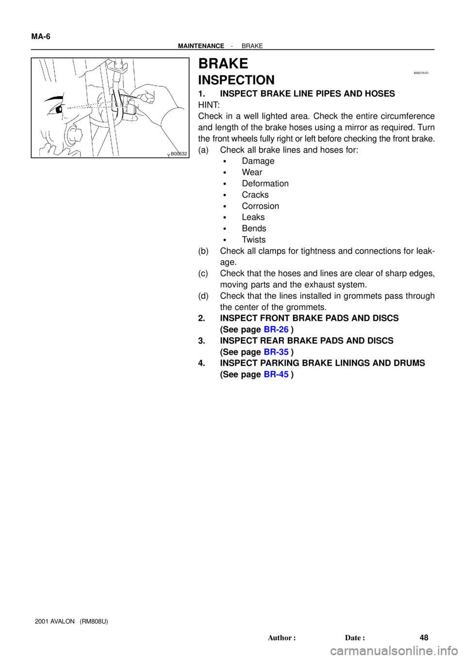
B00632
MA01N-01
MA-6
- MAINTENANCEBRAKE
48 Author�: Date�:
2001 AVALON (RM808U)
BRAKE
INSPECTION
1. INSPECT BRAKE LINE PIPES AND HOSES
HINT:
Check in a well lighted area. Check the entire circumference
and length of the brake hoses using a mirror as required. Turn
the front wheels fully right or left before checking the front brake.
(a) Check all brake lines and hoses for:
�Damage
�Wear
�Deformation
�Cracks
�Corrosion
�Leaks
�Bends
�Twists
(b) Check all clamps for tightness and connections for leak-
age.
(c) Check that the hoses and lines are clear of sharp edges,
moving parts and the exhaust system.
(d) Check that the lines installed in grommets pass through
the center of the grommets.
2. INSPECT FRONT BRAKE PADS AND DISCS
(See page BR-26)
3. INSPECT REAR BRAKE PADS AND DISCS
(See page BR-35)
4. INSPECT PARKING BRAKE LININGS AND DRUMS
(See page BR-45)
Page 1470 of 1897

INSIDE VEHICLE
GENERAL MAINTENANCE
These are maintenance and inspection items which are considered to be the owners")
MA002-16
MA-2
- MAINTENANCEINSIDE VEHICLE
44 Author�: Date�:
2001 AVALON (RM808U)
INSIDE VEHICLE
GENERAL MAINTENANCE
These are maintenance and inspection items which are considered to be the owner's responsibility.
They can be done by the owner or they can have them done at a service shop.
These items include those which should be checked on a daily basis, those which, in most cases, do not
require (special) tools and those which are considered to be reasonable for the owner to do.
Items and procedures for general maintenance are as follows.
1. GENERAL NOTES
�Maintenance items may vary from country to country. Check the owner's manual supplement in which
the maintenance schedule is shown.
�Every service item in the periodic maintenance schedule must be performed.
�Periodic maintenance service must be performed according to whichever interval in the periodic main-
tenance schedule occurs first, the odometer reading (miles) or the time interval (months).
�Maintenance service after the last period should be performed at the same interval as before unless
otherwise noted.
�Failure to do even one item an cause the engine to run poorly and increase exhaust emissions.
2. LIGHTS
(a) Check that the headlights, stop lights, taillights, turn signal lights, and other lights are all working.
(b) Check the headlight aim.
3. WARNING LIGHTS AND BUZZERS
Check that all warning lights and buzzers function properly.
4. HORN
Check that it is working.
5. WINDSHIELD GLASS
Check for scratches, pits or abrasions.
6. WINDSHIELD WIPER AND WASHER
(a) Check operation of the wipers and washer.
(b) Check that the wipers do not streak.
7. WINDSHIELD DEFROSTER
Check that air comes out from the defroster outlet when operating the heater or air conditioner at defroster
mode.
8. REAR VIEW MIRROR
Check that it is mounted securely.
9. SUN VISORS
Check that they move freely and are mounted securely.
10. STEERING WHEEL
Check that it has the specified free-play. Be alert for changes in steering condition, such as hard steering,
excessive free-play or strange noises.
11. SEATS
(a) Check that the seat adjusters operate smoothly.
(b) Check that all latches lock securely in any position.
(c) Check that the head restraints move up and down smoothly and that the locks hold securely in any
latch position.
(d) For fold-down seat backs, check that the latches lock securely.
12. SEAT BELTS
(a) Check that the seat belt system such as the buckles, retractors and anchors operate properly and
smoothly.
(b) Check that the belt webbing is not cut, frayed, worn or damaged.