Page 270 of 1897

I13309
9 62
3
7
I13310
9 62
3
7
I13311
8 62
7
1
I13312
8 62
7
1
I07530
SW1 SW2 SET Switch
BE-1 18
- BODY ELECTRICALPOWER MIRROR CONTROL SYSTEM
1722 Author�: Date�:
2001 AVALON (RM808U)
10. w/ Driving position memory:
INSPECT MIRROR POSITION SENSORS OPERATION
HINT:
Strip off the vinyl tape of the connector and remove terminals
2, 3, 6, 7 and 9 from the connector housing.
(a) Connect a series of three 1.5 V dry cell batteries.
(b) Connect the positive (+) lead from the dry cell batteries to
terminal 7 and the negative (-) lead to terminal 6.
(c) Connect the positive (+) lead from the voltmeter to termi-
nal 9 and the negative (-) lead to terminal 6.
(d) Apply Battery voltage to terminals 2 and 3, then check
that the voltage gradually changes according to the table
below while the mirror moves between the uppermost
position and lowermost position.
Mirror
positionLowermostMirror
positionUppermost
Voltage2.8 - 5.0Changes
gradually0 - 1.8
If voltage value is not as specified, replace the motor assembly.
(e) Disconnect the 4 leads of the battery and voltmeter.
(f) Connect the positive (+) lead from the voltmeter to termi-
nal 8 and negative (-) lead to terminal 6.
(g) Apply Battery voltage to terminals 2 and 1, then inspect
that the voltage gradually changes according to the table
below while the mirror moves between the left-most posi-
tion and right-most position.
Mirror
positionLeft-mostMirror
positionRight-most
Voltage
LEFT2.8 - 5.0Changes
gradually0 - 1.8
Voltage
RIGHT0 - 1.8Changes
gradually2.8 -5.0
If voltage value is not as specified, replace the motor assembly.
11. INSPECT DRIVING POSITION MEMORY AND RE-
TURN SWITCH CONTINUITY
Switch positionTester connectionSpecified condition
SET switch ON3 - 4Continuity
Return SW1 ON2 - 3Continuity
Return SW2 ON1 - 3Continuity
If continuity is not as specified, replace the switch.
Page 271 of 1897
BE1E5-01
I12539
Master Switch
Driver Side Junction Block
� ECU ACC Fuse
Mirror Assembly
�Mirror Motor
- BODY ELECTRICALPOWER MIRROR CONTROL SYSTEM
BE-1 13
1717 Author�: Date�:
2001 AVALON (RM808U)
POWER MIRROR CONTROL SYSTEM
LOCATION
Page 310 of 1897

BE-6
- BODY ELECTRICALTROUBLESHOOTING
1610 Author�: Date�:
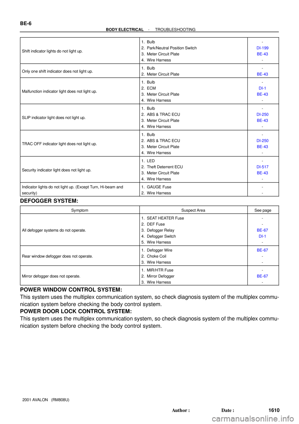
2001 AVALON (RM808U) Shift indicator lights do not light up.
1. Bulb
2. Park/Neutral Position Switch
3. Meter Circuit Plate
4. Wire Harness-
DI-199
BE-43
-
Only one shift indicator does not light up.1. Bulb
2. Meter Circuit Plate-
BE-43
Malfunction indicator light does not light up.
1. Bulb
2. ECM
3. Meter Circuit Plate
4. Wire Harness-
DI-1
BE-43
-
SLIP indicator light does not light up.
1. Bulb
2. ABS & TRAC ECU
3. Meter Circuit Plate
4. Wire Harness-
DI-250
BE-43
-
TRAC OFF indicator light does not light up.
1. Bulb
2. ABS & TRAC ECU
3. Meter Circuit Plate
4. Wire Harness-
DI-250
BE-43
-
Security indicator light does not light up.
1. LED
2. Theft Deterrent ECU
3. Meter Circuit Plate
4. Wire Harness-
DI-517
BE-43
-
Indicator lights do not light up. (Except Turn, Hi-beam and
security)1. GAUGE Fuse
2. Wire Harness-
-
DEFOGGER SYSTEM:
SymptomSuspect AreaSee page
All defogger systems do not operate.
1. SEAT HEATER Fuse
2. DEF Fuse
3. Defogger Relay
4. Defogger Switch
5. Wire Harness-
-
BE-67
DI-1
-
Rear window defogger does not operate.
1. Defogger Wire
2. Choke Coil
3. Wire HarnessBE-67
-
-
Mirror defogger does not operate.
1. MIR/HTR Fuse
2. Mirror Defogger
3. Wire Harness-
BE-67
-
POWER WINDOW CONTROL SYSTEM:
This system uses the multiplex communication system, so check diagnosis system of the multiplex commu-
nication system before checking the body control system.
POWER DOOR LOCK CONTROL SYSTEM:
This system uses the multiplex communication system, so check diagnosis system of the multiplex commu-
nication system before checking the body control system.
Page 312 of 1897

BE-8
- BODY ELECTRICALTROUBLESHOOTING
1612 Author�: Date�:
2001 AVALON (RM808U)
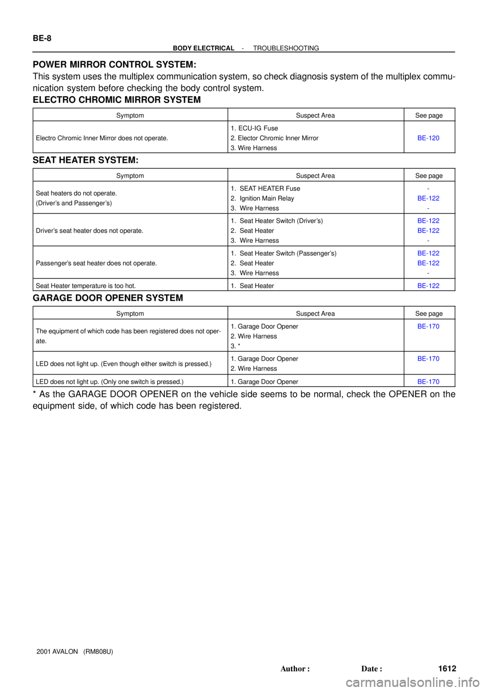
POWER MIRROR CONTROL SYSTEM:
This system uses the multiplex communication system, so check diagnosis system of the multiplex commu-
nication system before checking the body control system.
ELECTRO CHROMIC MIRROR SYSTEM
SymptomSuspect AreaSee page
Electro Chromic Inner Mirror does not operate.
1. ECU-IG Fuse
2. Elector Chromic Inner Mirror
3. Wire Harness
BE-120
SEAT HEATER SYSTEM:
SymptomSuspect AreaSee page
Seat heaters do not operate.
(Driver's and Passenger's)1. SEAT HEATER Fuse
2. Ignition Main Relay
3. Wire Harness-
BE-122
-
Driver's seat heater does not operate.
1. Seat Heater Switch (Driver's)
2. Seat Heater
3. Wire HarnessBE-122
BE-122
-
Passenger's seat heater does not operate.
1. Seat Heater Switch (Passenger's)
2. Seat Heater
3. Wire HarnessBE-122
BE-122
-
Seat Heater temperature is too hot.1. Seat HeaterBE-122
GARAGE DOOR OPENER SYSTEM
SymptomSuspect AreaSee page
The equipment of which code has been registered does not oper-
ate.1. Garage Door Opener
2. Wire Harness
3. *BE-170
LED does not light up. (Even though either switch is pressed.)1. Garage Door Opener
2. Wire HarnessBE-170
LED does not light up. (Only one switch is pressed.)1. Garage Door OpenerBE-170
* As the GARAGE DOOR OPENER on the vehicle side seems to be normal, check the OPENER on the
equipment side, of which code has been registered.
Page 347 of 1897

BO2OO-01
H12112
Rear Lower FrameDoor Lock Striker23 (230, 17)
Front Door Weatherstrip
Door Glass Run
Outside Rear View
Mirror
Door Glass
Lower Frame
Bracket Garnish
7.8 (80, 69 in.´lbf)25 (260, 19)
5.4 (55, 48 in.´lbf)
Outside Handle
Key Cylinder
5.4 (55, 48 in.´lbf)
Door
Hinge
7.8 (80, 69 in.´lbf)
Door Check
25 (260, 19)
Door Speaker BoardFront Lower
Frame
25 (260, 19)
Door Hinge
Front Door Outside Lower Moulding
Door Lock Protector
Service Hole Cover
5.4 (55, 48 in.´lbf)
� Precoated part
Door LockInside Handle
4.9 (50, 43 in.´lbf)
Inside Handle
Bezel
Cover
Door TrimUpper Armrest
Base Panel
Power Window Switch
Front Door Armrest
Courtesy Light
Front Door
Belt Moulding Front Door
Inner Weatherstrip
x10
5.4 (55, 48 in.´lbf)
Window Regulator
Guide Assembly
5.4 (55, 48 in.´lbf)
x8
x4
Window Regulator Motor
No. 2 Service Hole Cover
Front Door Trim Pocket : Specified torqueN´m (kgf´cm, ft´lbf)
BO-8
- BODYFRONT DOOR
1793 Author�: Date�:
2001 AVALON (RM808U)
FRONT DOOR
COMPONENTS
Page 349 of 1897

H12104Clip
H06127
H12105
H12106
BO-10
- BODYFRONT DOOR
1795 Author�: Date�:
2001 AVALON (RM808U)
5. REMOVE LOWER FRAME BRACKET GARNISH
Using a screwdriver, remove the lower frame bracket as shown
in the illustration.
HINT:
Tape the screwdriver tip before use.
6. REMOVE OUTSIDE REAR VIEW MIRROR
Torque: 7.8 N´m (80 kgf´cm, 69 ft´lbf)
7. REMOVE DOOR SPEAKER BOARD
8. REMOVE INSIDE HANDLE
(a) Remove the screw.
(b) Slide the inside handle backward to remove it.
(c) Disconnect the 2 cables from the inside handle as shown
in the illustration.
9. REMOVE SERVICE HOLE COVER
(a) Using a clip remover, remove the grommets.
(b) Remove the service hole cover.
NOTICE:
Do not tear the cover.
HINT:
At the time of reassembly, please refer to the following item.
Bring out the 2 control cables and wire harness through the ser-
vice hole cover.
10. REMOVE FRONT DOOR WEATHERSTRIP
(a) Using a clip remover, remove the clip.
(b) Remove the screw from the door check.
(c) Using a clip remover, remove the front door weatherstrip.
(d) Reinstall the screw to the door check.
Torque: 25 N´m (260 kgf´cm, 19 ft´lbf)
Page 407 of 1897
BO41E-01
H17368
Outside Rear View Mirror
7.8 (80, 69 in.´lbf)
MirrorWire Retainer
Lower Frame
Bracket Garnish
Gasket
Door Trim Upper Armrest Base
Panel with Power
Window SwitchInside Handle Bezel
Courtesy Light
N´m (kgf´cm, ft´lbf) : Specified torqueTAIWAN:
Mirror
7.8 (80, 69 in.´lbf)
Outside Rear
View Mirror
- BODYOUTSIDE REAR VIEW MIRROR
BO-25
1810 Author�: Date�:
2001 AVALON (RM808U)
OUTSIDE REAR VIEW MIRROR
COMPONENTS
Page 408 of 1897
BO41H-01
- BODYOUTSIDE REAR VIEW MIRROR
BO-29
1814 Author�: Date�:
2001 AVALON (RM808U)
INSTALLATION
Installation is in the reverse order of removal (See page BO-26).