Page 1384 of 1897

P18815
EM-24
- ENGINE MECHANICALTIMING BELT
1008 Author�: Date�:
2001 AVALON (RM808U)
10. CHECK VALVE TIMING
(a) Slowly turn the crankshaft 2 revol")
P18808
A05052
P12983
Length = 1,410 mm (55.51 in.)
P18815
EM-24
- ENGINE MECHANICALTIMING BELT
1008 Author�: Date�:
2001 AVALON (RM808U)
10. CHECK VALVE TIMING
(a) Slowly turn the crankshaft 2 revolutions, and align the tim-
ing marks of the crankshaft timing pulley and oil pump
body.
NOTICE:
Always turn the crankshaft clockwise.
(b) Check that the timing marks of the RH and LH timing pul-
leys with the timing marks of the No.3 timing belt cover as
shown in the illustration.
If the marks do not align, remove the timing belt and reinstall it.
(c) Remove the crankshaft pulley bolt.
11. INSTALL RH ENGINE MOUNTING BRACKET
Torque: 28 N´m (290 kgf´cm, 21 ft´lbf)
12. INSTALL NO.2 TIMING BELT COVER
(a) Check that the timing belt cover gasket has no cracks or
peeling, etc.
If the gasket has cracks or peeling, etc., replace it using these
steps:
�Using a screwdriver and gasket scraper, remove all
the old gasket material.
�Thoroughly clean all components to remove all the
loose material.
�Remove the backing paper from a new gasket and
install the gasket evenly to the part of the timing belt
cover shaded black in the illustration.
�After installing the gasket, press down on it so that
the adhesive firmly sticks to the timing belt cover.
(b) Install the timing belt cover with the 5 bolts.
Torque: 8.5 N´m (85 kgf´cm, 74 in.´lbf)
(c) Install the engine wire protector clamps to the No.3 timing
belt cover.
13. INSTALL TIMING BELT GUIDE
Install the timing belt guide, facing the cup side outward.
Page 1385 of 1897

Join
Line
Join
Line
Length = 460 mm
(18.11 in.)
A04693
SST
P18816
- ENGINE MECHANICALTIMING BELT
EM-25
1009 Author�: Date�:
2001 AVALON (RM808U)
14. INSTALL NO.1 TI")
P12982
Length = 240 mm (9.45 in.)
Join
Line
Join
Line
Length = 460 mm
(18.11 in.)
A04693
SST
P18816
- ENGINE MECHANICALTIMING BELT
EM-25
1009 Author�: Date�:
2001 AVALON (RM808U)
14. INSTALL NO.1 TIMING BELT COVER
(a) Check that the timing belt cover gaskets have cracks or
peeling, etc.
If the gasket has cracks or peeling, etc., replace it using these
steps:
�Using a screwdriver and gasket scraper, remove all
the old gasket material.
�Thoroughly clean all components to remove all the
loose material.
�Remove the backing paper from a new gasket and
install the gasket evenly to the part of the timing belt
cover shaded black in the illustration.
NOTICE:
When joining 2 gaskets, do not leave a gap between them.
Cut off any excess gasket.
�After installing the gasket, press down on it so that
the adhesive firmly sticks to the timing belt cover.
(b) Install the timing belt cover with the 4 bolts.
Torque: 8.5 N´m (85 kgf´cm, 74 in.´lbf)
15. INSTALL CRANKSHAFT PULLEY
(a) Align the pulley set key with the key groove of the pulley,
and slide on the pulley.
(b) Using SST, install the pulley bolt.
SST 09213-54015 (91651-60855), 09330-00021
Torque: 215 N´m (2,200 kgf´cm, 159 ft´lbf)
16. INSTALL NO.2 GENERATOR BRACKET
Install the generator bracket with the pivot bolt and nut. Do not
tighten the bolt yet.
Torque: (Nut): 28 N´m (290 kgf´cm, 21 ft´lbf)
17. INSTALL NO.2 RH ENGINE MOUNTING BRACKET
AND ENGINE MOVING CONTROL ROD
(See page EM-77)
18. CONNECT GROUND STRAP CONNECTORS
19. CONNECT ENGINE COOLANT RESERVOIR HOSE TO
WATER OUTLET
20. INSTALL PS PUMP DRIVE BELT
21. INSTALL GENERATOR DRIVE BELT
(See page CH-16)
22. INSTALL RH FENDER APRON SEAL
23. INSTALL RH FRONT WHEEL
24. VEHICLE ROAD TEST
Check for abnormal noise, shock, slippage, correct shift points
and smoothly operation.
Page 1442 of 1897
 H-FUSE
High Current Fuse
HIHigh
HIDHigh Intensity Discharge (Head Lamp)
HSGHousing
HTHard Top
HWSHeated Windshield System
IACIdle Ai")
- INTRODUCTIONTERMS
IN-37
37 Author�: Date�:
2001 AVALON (RM808U) H-FUSE
High Current Fuse
HIHigh
HIDHigh Intensity Discharge (Head Lamp)
HSGHousing
HTHard Top
HWSHeated Windshield System
IACIdle Air Control
ICIntegrated circuit
IDIIndirect Diesel Injection
IFSIndependent Front Suspension
IGIgnition
IIAIntegrated Ignition Assembly
INIntake (Manifold, Valve)
INTIntermittent
I/PInstrument Panel
IRSIndependent Rear Suspension
J/BJunction Block
J/CJunction Connector
KDKick-Down
LANLocal Area Network
LBLiftback
LCDLiquid Crystal Display
LEDLight Emitting Diode
LHLeft-Hand
LHDLeft-Hand Drive
L/H/WLength, Height, Width
LLCLong-Life Coolant
LNGLiquified Natural Gas
LOLow
LPGLiquified Petroleum Gas
LSDLimited Slip Differential
LSP & PVLoad Sensing Proportioning And Bypass Valve
LSPVLoad Sensing Proportioning Valve
MAX.Maximum
MICMicrophone
MILMalfunction Indicator Lamp
MIN.Minimum
MPMultipurpose
MPXMultiplex Communication System
M/TManual Transmission
MTMount
MTGMounting
NNeutral
NANatural Aspiration
No.Number
O/DOverdrive
Page 1450 of 1897

REPLACEMENT
CAUTION:
�Prolonged and repeated contact with miner")
LU01Q-03
B06524
B06486
SST
B06479
SST
Additional
3/4 Turn
- LUBRICATIONOIL AND FILTER
LU-3
1228 Author�: Date�:
2001 AVALON (RM808U)
REPLACEMENT
CAUTION:
�Prolonged and repeated contact with mineral oil will
result in the removal of natural fats from the skin,
leading to dryness, irritation and dermatitis. In addi-
tion, used engine oil contains potentially harmful
contaminants which may cause skin cancer.
�Exercise caution in order to minimize the length and
frequency of contact of your skin to used oil. Wear
protective clothing and gloves. Wash your skin thor-
oughly with soap and water, or use water-less hand
cleaner, to remove any used engine oil. Do not use
gasoline, thinners, or solvents.
�In order to preserve the environment, used oil and
used oil filter must be disposed of only at designated
disposal sites.
1. DRAIN ENGINE OIL
(a) Remove the oil filler cap.
(b) Remove the oil drain plug, and drain the oil into a contain-
er.
2. REPLACE OIL FILTER
(a) Using SST, remove the oil filter.
SST 09228-07501
(b) Check and clean the oil filter installation surface.
(c) Apply clean engine oil to the gasket of a new oil filter.
(d) Lightly screw the oil filter into place, and tighten it until the
gasket contacts the seat.
(e) Using SST, tighten it an additional 3/4 turn.
SST 09228-07501
Page 1467 of 1897
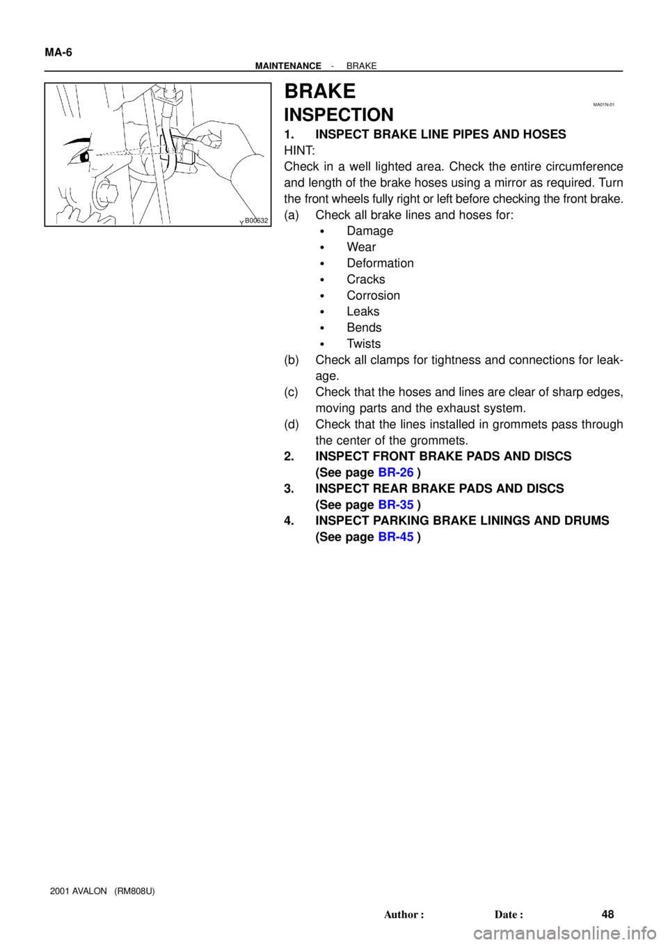
B00632
MA01N-01
MA-6
- MAINTENANCEBRAKE
48 Author�: Date�:
2001 AVALON (RM808U)
BRAKE
INSPECTION
1. INSPECT BRAKE LINE PIPES AND HOSES
HINT:
Check in a well lighted area. Check the entire circumference
and length of the brake hoses using a mirror as required. Turn
the front wheels fully right or left before checking the front brake.
(a) Check all brake lines and hoses for:
�Damage
�Wear
�Deformation
�Cracks
�Corrosion
�Leaks
�Bends
�Twists
(b) Check all clamps for tightness and connections for leak-
age.
(c) Check that the hoses and lines are clear of sharp edges,
moving parts and the exhaust system.
(d) Check that the lines installed in grommets pass through
the center of the grommets.
2. INSPECT FRONT BRAKE PADS AND DISCS
(See page BR-26)
3. INSPECT REAR BRAKE PADS AND DISCS
(See page BR-35)
4. INSPECT PARKING BRAKE LININGS AND DRUMS
(See page BR-45)
Page 1524 of 1897
PP0MS-01
PP-52
- PREPARATIONSUPPLEMENTAL RESTRAINT SYSTEM
102 Author�: Date�:
2001 AVALON (RM808U)
EQUIPMENT
Torque wrench
Bolt: Length: 35 mm (1.38 in.) Pitch: 1.0 mm (0.039 in.)
Diam.: 6.0 mm (0.236 in.)Airbag disposal
Tire Width: 185 mm (7.28 in.) Inner diam.: 360mm (14.17 in.)Airbag disposal
Tire with disc wheel Width: 185 mm (7.28 in.)
Inner diam.: 360 mm (14.17 in.)Airbag disposal
Vinyl bagAirbag disposal
Page 1559 of 1897
SS0ET-02
SS-22
- SERVICE SPECIFICATIONSCHARGING
138 Author�: Date�:
2001 AVALON (RM808U)
CHARGING
SERVICE DATA
BatterySpecific gravity
(Except maintenance-free battery) at 20°C (68°F)
Voltage
(Maintenance-free battery) at 20°C (68°F)
1.25 - 1.29
12.5 - 12.9 V
Drive beltTension
New belt
Used belt
175 ± 5 lbf
115 ± 20 lbf
GeneratorRated output
Rotor coil resistance at 20°C (68°F)
Slip ring diameter STD
Minimum
Brush exposed length STD
Minimum12 V 100 A
2.1 - 2.5 W
14.2 - 14.4 mm (0.559 - 0.567 in.)
12.8 mm (0.504 in.)
10.5 mm (0.413 in.)
1.5 mm (0.059 in.)
Voltage regulatorRegulating voltage13.2 - 14.8 V
Page 1564 of 1897

ENGINE MECHANICAL
SERVICE DATA
Compression
pressureat 250 rpm STD
Minimum
Difference of pressure bet")
SS0EF-02
SS-6
- SERVICE SPECIFICATIONSENGINE MECHANICAL
122 Author�: Date�:
2001 AVALON (RM808U)
ENGINE MECHANICAL
SERVICE DATA
Compression
pressureat 250 rpm STD
Minimum
Difference of pressure between each cylinder1,500 kPa (15.3 kgf/cm2, 218 psi)
1,000 kPa (10.2 kgf/cm2, 145 psi)
100 kPa (1.0 kgf/cm2, 15 psi) or less
Valve
clearanceat cold Intake
Exhaust
Adjusting shim for repair part Mark 2.500
Mark 2.550
Mark 2.600
Mark 2.650
Mark 2.700
Mark 2.750
Mark 2.800
Mark 2.850
Mark 2.900
Mark 2.950
Mark 3.000
Mark 3.050
Mark 3.100
Mark 3.150
Mark 3.200
Mark 3.250
Mark 3.3000.15 - 0.25 mm (0.006 - 0.010 in.)
0.25 - 0.35 mm (0.010 - 0.014 in.)
2.500 mm (0.0984 in.)
2.550 mm (0.1004 in.)
2.600 mm (0.1024 in.)
2.650 mm (0.1043 in.)
2.700 mm (0.1063 in.)
2.750 mm (0.1083 in.)
2.800 mm (0.1102 in.)
2.850 mm (0.1122 in.)
2.900 mm (0.1142 in.)
2.950 mm (0.1161 in.)
3.000 mm (0.1181 in.)
3.050 mm (0.1201 in.)
3.100 mm (0.1220 in.)
3.150 mm (0.1240 in.)
3.200 mm (0.1260 in.)
3.250 mm (0.1280 in.)
3.300 mm (0.1299 in.)
Ignition timingw/ Terminals TE1 and E1 connected of DLC18 - 12° BTDC @ idle
Idle speed-650 ± 50 rpm
Timing belt
tensionerProtrusion from housing side10.0 - 10.8 mm (0.394 - 0.425 in.)
Cylinder headWarpage Maximum
Valve seat
Refacing angle
Contacting angle
Contacting width
Valve guide bushing bore diameter STD
O/S 0.05
12 pointed head cylinder head bolt diameter
at tension portion STD
Minimum0.10 mm (0.039 in.)
30°, 45°, 75°
45°
1.0 - 1.4 mm (0.039 - 0.055 in.)
10.295 - 10.313 mm (0.4053 - 0.4080 in.)
10.345 - 10.363 mm (0.4073 - 0.4080 in.)
8.95 - 9.05 mm (0.3524 - 0.3563 in.)
8.75 mm (0.3445 in.)
Valve guide
bushingInside diameter
Outside diameter for repair part STD
O/S 0.055.510 - 5.530 mm (0.2169 - 0.2177 in.)
10.333 - 10.344 mm (0.4068 - 0.4072 in.)
10.383 - 10.394 mm (0.4088 - 0.4092 in.)
ValveValve overall length STD Intake
Exhaust
Minimum Intake
Exhaust
Valve face angle
Stem diameterIntake
Exhaust
Stem oil clearance STD Intake
Exhaust
Maximum Intake
Exhaust
Margin thickness STD
Maximum95.45 mm (3.5779 in.)
95.40 mm (3.7559 in.)
94.95 mm (3.7382 in.)
94.90 mm (3.7362 in.)
44.5°
5.470 - 5.485 mm (0.2154 - 0.2159 in.)
5.465 - 5.480 mm (0.2152 - 0.2157 in.)
0.025 - 0.060 mm (0.0010 - 0.0024 in.)
0.030 - 0.065 mm (0.0012 - 0.0026 in.)
0.08 mm (0.0031 in.)
0.10 mm (0.0039 in.)
1.0 mm (0.039 in.)
0.5 mm (0.020 in.)