Page 1007 of 1897
A02397
OCV Signal Waveform
1 m sec./Division5 V/
Division
GND
(A) (A) (A)
DI-128
- DIAGNOSTICSENGINE
284 Author�: Date�:
2001 AVALON (RM808U)
TOYOTA hand-held tester:
1 Check valve timing (See page EM-15).
NG Repair valve timing.
OK
2 Check operation of OCV.
PREPARATION:
(a) Start the engine and warmed it up.
(b) Connect the TOYOTA hand-held tester and select the VVT from the ACTIVE TEST menu.
CHECK:
Check the engine speed when operate the OCV by the TOYOTA hand-held tester.
OK:
OCV is OFF: Normal engine speed
OCV is ON: Rough idle or engine stall
OK VVT system is OK.*
*: DTCs P1349 and P1354 are also output after the foreign ob-
ject is caught in some part of the system in the engine oil and
the system returns to normal in a short time. As ECM controls
so that foreign objects are ejected, there is no problem about
VVT. There is also no problem since the oil filter should get the
foreign object in the engine oil.
NG
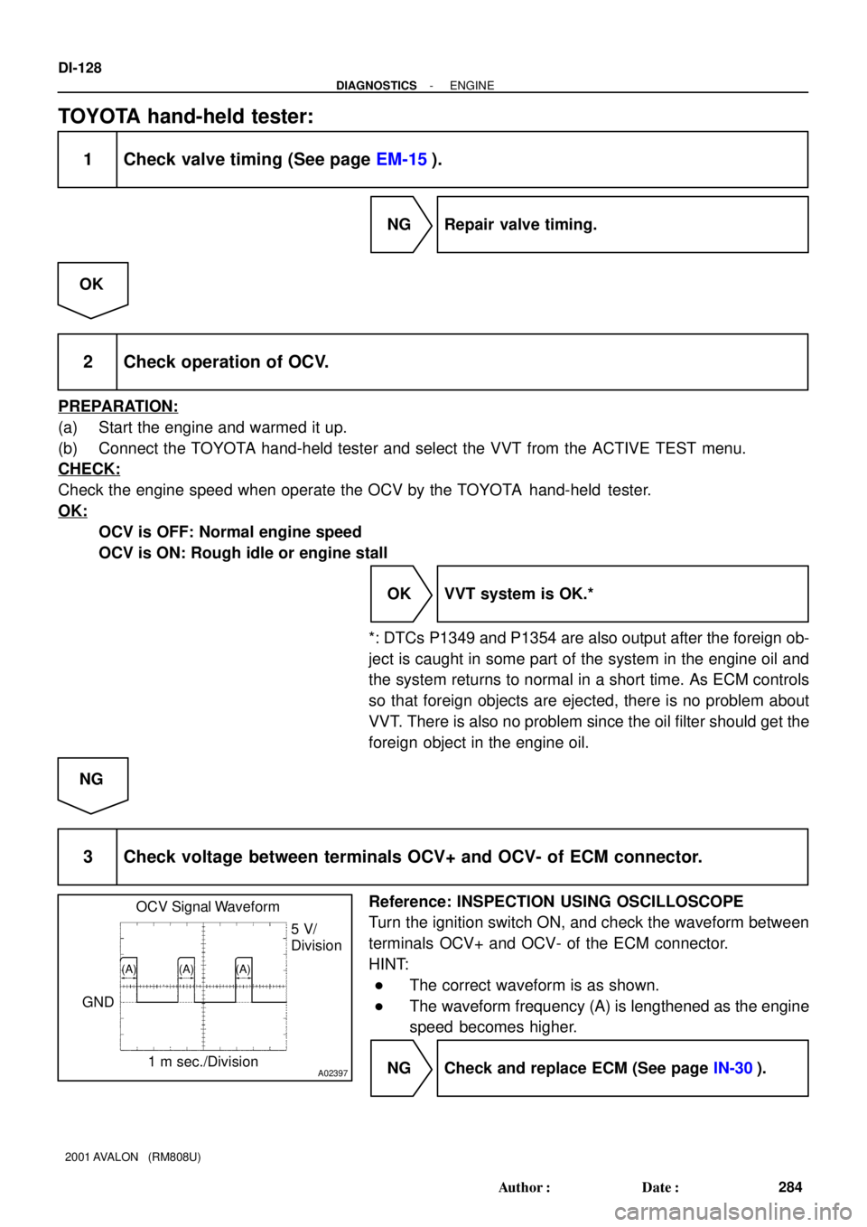
3 Check voltage between terminals OCV+ and OCV- of ECM connector.
Reference: INSPECTION USING OSCILLOSCOPE
Turn the ignition switch ON, and check the waveform between
terminals OCV+ and OCV- of the ECM connector.
HINT:
�The correct waveform is as shown.
�The waveform frequency (A) is lengthened as the engine
speed becomes higher.
NG Check and replace ECM (See page IN-30).
Page 1010 of 1897
A06076
OCV Connector(a)
(b)
A02397
OCV Signal Waveform
1 msec./Division5 V/
Division
GND
(A) (A) (A)
- DIAGNOSTICSENGINE
DI-131
287 Author�: Date�:
2001 AVALON (RM808U)
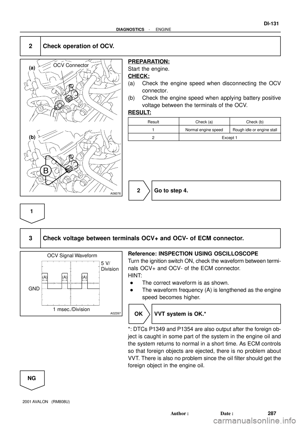
2 Check operation of OCV.
PREPARATION:
Start the engine.
CHECK:
(a) Check the engine speed when disconnecting the OCV
connector.
(b) Check the engine speed when applying battery positive
voltage between the terminals of the OCV.
RESULT:
ResultCheck (a)Check (b)
1Normal engine speedRough idle or engine stall
2Except 1
2 Go to step 4.
1
3 Check voltage between terminals OCV+ and OCV- of ECM connector.
Reference: INSPECTION USING OSCILLOSCOPE
Turn the ignition switch ON, check the waveform between termi-
nals OCV+ and OCV- of the ECM connector.
HINT:
�The correct waveform is as shown.
�The waveform frequency (A) is lengthened as the engine
speed becomes higher.
OK VVT system is OK.*
*: DTCs P1349 and P1354 are also output after the foreign ob-
ject is caught in some part of the system in the engine oil and
the system returns to normal in a short time. As ECM controls
so that foreign objects are ejected, there is no problem about
VVT. There is also no problem since the oil filter should get the
foreign object in the engine oil.
NG
Page 1328 of 1897

EM2534
Overall Length
EM0255
A05228
P12729
Width
Z03988
45°
1.0 - 1.4 mm30°
- ENGINE MECHANICALCYLINDER HEAD
EM-45
1029 Author�: Date�:
2001 AVALON (RM808U)
(d) Check the valve overall length.
Standard overall length:
Intake95.45 mm (3.5779 in.)
Exhaust95.40 mm (3.7559 in.)
Minimum overall length:
Intake94.95 mm (3.7382 in.)
Exhaust94.90 mm (3.7362 in.)
If the overall length is less than minimum, replace the valve.
(e) Check the surface of the valve stem tip for wear.
If the valve stem tip is worn, resurface the tip with a grinder or
replace the valve.
NOTICE:
Do not grind off more than minimum.
11. INSPECT AND CLEAN VALVE SEATS
(a) Using a 45° carbide cutter, resurface the valve seats.
Remove only enough metal to clean the seats.
(b) Check the valve seating position.
Apply a light coat of prussian blue (or white lead) to the
valve face. Lightly press the valve against the seat. Do not
rotate valve.
(c) Check the valve face and seat for the following:
�If blue appears 360° around the face, the valve is
concentric. If not, replace the valve.
�If blue appears 360° around the valve seat, the
guide and face are concentric. If not, resurface the
seat.
�Check that the seat contact is in the middle of the
valve face with the following width:
1.0 - 1.4 mm (0.039 - 0.055 in.)
If not, correct the valve seats as follows:
(1) If the seating is too high on the valve face, use 30°
and 45° cutters to correct the seat.
Page 1329 of 1897

Z03989
45°
1.0 - 1.4 mm75°
P12705
EM0988
Deviation
EM0801
EM0281
EM-46
- ENGINE MECHANICALCYLINDER HEAD
1030 Author�: Date�:
2001 AVALON (RM808U)
(2) If the seating is too low on the valve face, use 75°
and 45° cutters to correct the seat.
(d) Hand-lap the valve and valve seat with an abrasive com-
pound.
(e) After hand-lapping, clean the valve and valve seat.
12. INSPECT VALVE SPRINGS
(a) Using a steel square, measure the deviation of the valve
spring.
Maximum deviation: 2.0 mm (0.079 in.)
If the deviation is greater than maximum, replace the valve
spring.
(b) Using vernier calipers, measure the free length of the
valve spring.
Free length: 45.50 mm (1.7913 in.)
If the free length is not as specified, replace the valve spring.
(c) Using a spring tester, measure the tension of the valve
spring at the specified installed length.
Installed tension:
186 - 206 N (19.0 - 21.0 kgf, 41.9 - 46.3 lbf)
at 33.8 mm (1.331 in.)
If the installed tension is not as specified, replace the valve
spring.
Page 1343 of 1897
A05194
L = 133 mm (5.24 in.)
L = 180 mm (7.09 in.)L = 72 mm (2.83 in.)
L = 335 mm (13.19 in.)L = 180 mm
(7.09 in.)
L = Length Join
LineJoin
Line
Z14262New Gasket
- ENGINE MECHANICALCYLINDER HEAD
EM-67
1051 Author�: Date�:
2001 AVALON (RM808U)
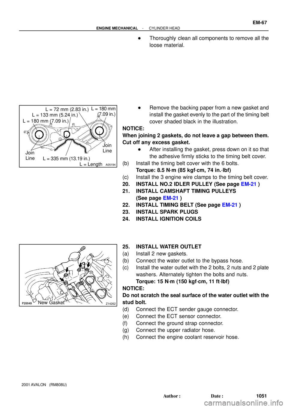
�Thoroughly clean all components to remove all the
loose material.
�Remove the backing paper from a new gasket and
install the gasket evenly to the part of the timing belt
cover shaded black in the illustration.
NOTICE:
When joining 2 gaskets, do not leave a gap between them.
Cut off any excess gasket.
�After installing the gasket, press down on it so that
the adhesive firmly sticks to the timing belt cover.
(b) Install the timing belt cover with the 6 bolts.
Torque: 8.5 N´m (85 kgf´cm, 74 in.´lbf)
(c) Install the 3 engine wire clamps to the timing belt cover.
20. INSTALL NO.2 IDLER PULLEY (See page EM-21)
21. INSTALL CAMSHAFT TIMING PULLEYS
(See page EM-21)
22. INSTALL TIMING BELT (See page EM-21)
23. INSTALL SPARK PLUGS
24. INSTALL IGNITION COILS
25. INSTALL WATER OUTLET
(a) Install 2 new gaskets.
(b) Connect the water outlet to the bypass hose.
(c) Install the water outlet with the 2 bolts, 2 nuts and 2 plate
washers. Alternately tighten the bolts and nuts.
Torque: 15 N´m (150 kgf´cm, 11 ft´lbf)
NOTICE:
Do not scratch the seal surface of the water outlet with the
stud bolt.
(d) Connect the ECT sender gauge connector.
(e) Connect the ECT sensor connector.
(f) Connect the ground strap connector.
(g) Connect the upper radiator hose.
(h) Connect the engine coolant reservoir hose.
Page 1354 of 1897
A05195
IntakeMain Gear
Sub-Gear
Service Bolt
A05207
Intake
7
8
5
6
3
41 2
9
10
A05197
7
85
6
3
41
2
9
10 Exhaust EM-36
- ENGINE MECHANICALCYLINDER HEAD
1020 Author�: Date�:
2001 AVALON (RM808U)
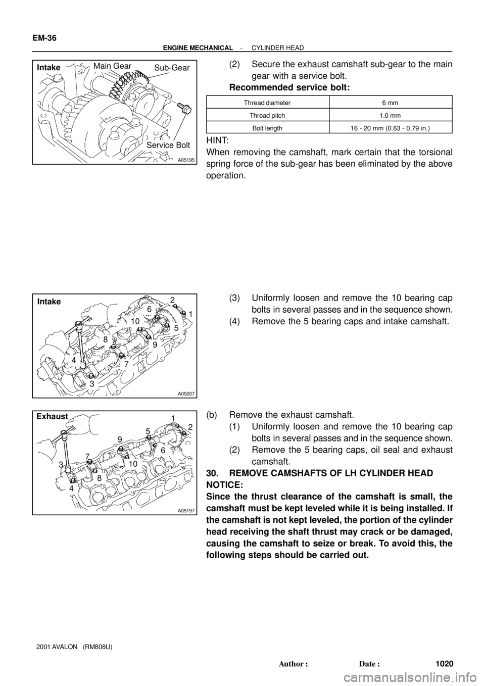
(2) Secure the exhaust camshaft sub-gear to the main
gear with a service bolt.
Recommended service bolt:
Thread diameter6 mm
Thread pitch1.0 mm
Bolt length16 - 20 mm (0.63 - 0.79 in.)
HINT:
When removing the camshaft, mark certain that the torsional
spring force of the sub-gear has been eliminated by the above
operation.
(3) Uniformly loosen and remove the 10 bearing cap
bolts in several passes and in the sequence shown.
(4) Remove the 5 bearing caps and intake camshaft.
(b) Remove the exhaust camshaft.
(1) Uniformly loosen and remove the 10 bearing cap
bolts in several passes and in the sequence shown.
(2) Remove the 5 bearing caps, oil seal and exhaust
camshaft.
30. REMOVE CAMSHAFTS OF LH CYLINDER HEAD
NOTICE:
Since the thrust clearance of the camshaft is small, the
camshaft must be kept leveled while it is being installed. If
the camshaft is not kept leveled, the portion of the cylinder
head receiving the shaft thrust may crack or be damaged,
causing the camshaft to seize or break. To avoid this, the
following steps should be carried out.
Page 1355 of 1897
A05284Align Intake
A05198
Intake
Main GearSub-GearService Bolt
A05199
Intake
7
85
6
3
4
1
2
9
10
A05200
7
8
5
6
3
4
1
2
9
10 Exhaust
- ENGINE MECHANICALCYLINDER HEAD
EM-37
1021 Author�: Date�:
2001 AVALON (RM808U)
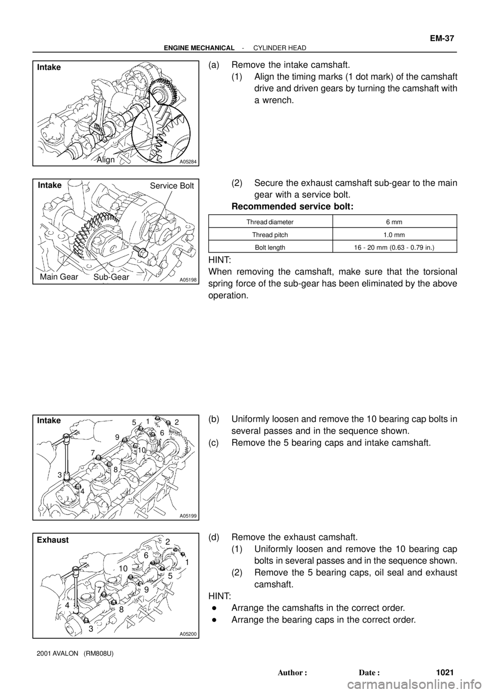
(a) Remove the intake camshaft.
(1) Align the timing marks (1 dot mark) of the camshaft
drive and driven gears by turning the camshaft with
a wrench.
(2) Secure the exhaust camshaft sub-gear to the main
gear with a service bolt.
Recommended service bolt:
Thread diameter6 mm
Thread pitch1.0 mm
Bolt length16 - 20 mm (0.63 - 0.79 in.)
HINT:
When removing the camshaft, make sure that the torsional
spring force of the sub-gear has been eliminated by the above
operation.
(b) Uniformly loosen and remove the 10 bearing cap bolts in
several passes and in the sequence shown.
(c) Remove the 5 bearing caps and intake camshaft.
(d) Remove the exhaust camshaft.
(1) Uniformly loosen and remove the 10 bearing cap
bolts in several passes and in the sequence shown.
(2) Remove the 5 bearing caps, oil seal and exhaust
camshaft.
HINT:
�Arrange the camshafts in the correct order.
�Arrange the bearing caps in the correct order.
Page 1381 of 1897
EM0ZD-02
A05060
Inward
Sensor
A01802
10 mm
Hexagon
Wrench
Plate Washer
A05055
A05061
Fulcrum
Length
SSTSST
RH
- ENGINE MECHANICALTIMING BELT
EM-21
1005 Author�: Date�:
2001 AVALON (RM808U)
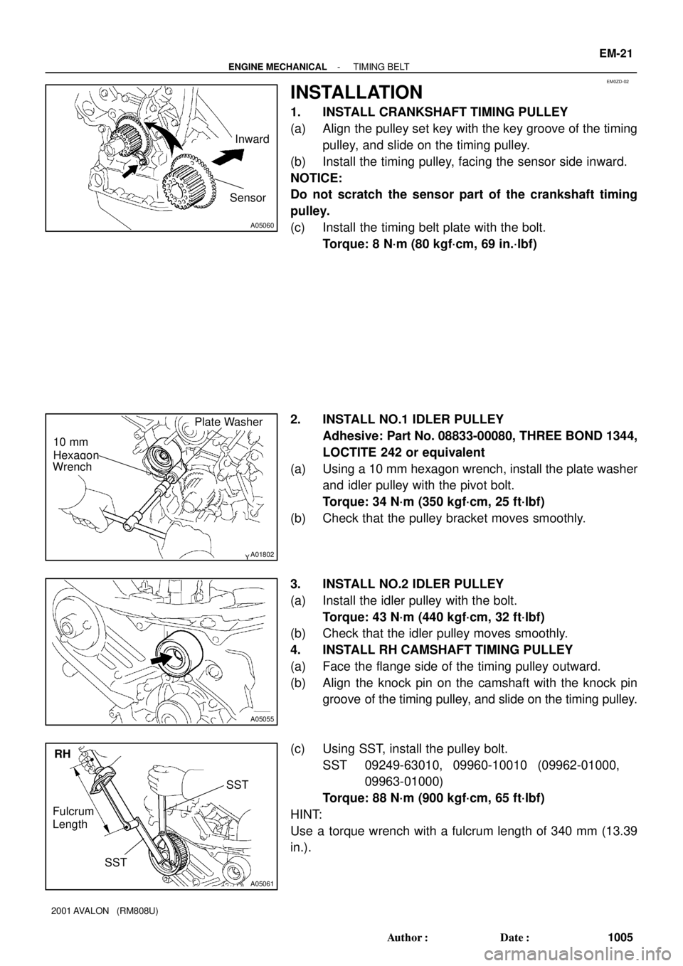
INSTALLATION
1. INSTALL CRANKSHAFT TIMING PULLEY
(a) Align the pulley set key with the key groove of the timing
pulley, and slide on the timing pulley.
(b) Install the timing pulley, facing the sensor side inward.
NOTICE:
Do not scratch the sensor part of the crankshaft timing
pulley.
(c) Install the timing belt plate with the bolt.
Torque: 8 N´m (80 kgf´cm, 69 in.´lbf)
2. INSTALL NO.1 IDLER PULLEY
Adhesive: Part No. 08833-00080, THREE BOND 1344,
LOCTITE 242 or equivalent
(a) Using a 10 mm hexagon wrench, install the plate washer
and idler pulley with the pivot bolt.
Torque: 34 N´m (350 kgf´cm, 25 ft´lbf)
(b) Check that the pulley bracket moves smoothly.
3. INSTALL NO.2 IDLER PULLEY
(a) Install the idler pulley with the bolt.
Torque: 43 N´m (440 kgf´cm, 32 ft´lbf)
(b) Check that the idler pulley moves smoothly.
4. INSTALL RH CAMSHAFT TIMING PULLEY
(a) Face the flange side of the timing pulley outward.
(b) Align the knock pin on the camshaft with the knock pin
groove of the timing pulley, and slide on the timing pulley.
(c) Using SST, install the pulley bolt.
SST 09249-63010, 09960-10010 (09962-01000,
09963-01000)
Torque: 88 N´m (900 kgf´cm, 65 ft´lbf)
HINT:
Use a torque wrench with a fulcrum length of 340 mm (13.39
in.).