Page 547 of 1897

TROUBLESHOOTING
PROBLEM SYMPTOMS TABLE
Use the table below to help you find the cause of the problem. The numbers indic")
BR0KG-05
BR-2
- BRAKETROUBLESHOOTING
1401 Author�: Date�:
2001 AVALON (RM808U)
TROUBLESHOOTING
PROBLEM SYMPTOMS TABLE
Use the table below to help you find the cause of the problem. The numbers indicate the priority of the likely
cause of the problem. Check each part in order. If necessary, replace these parts.
SymptomSuspect AreaSee page
Lower pedal or spongy pedal
5. Fluid leaks for brake system
6. Air in brake system
7. Piston seals (Worn or damaged)
8. Master cylinder (Faulty)
9. Booster push rod (Out of adjustment)DI-249
DI-346
BR-4
BR-28
BR-37
BR-13
BR-24
Brake drag
1. Brake pedal freeplay (Minimal)
2. Parking brake pedal travel (Out of adjustment)
3. Parking brake wire (Sticking)
4. Rear brake shoe clearance (Out of adjustment)
5. Pad (Cracked or distorted)
6. Piston (Stuck)
7. Piston (Frozen)
8. Tension or return spring (Faulty)
9. Booster push rod (Out of adjustment)
10.Vacuum leaks for booster system
11. Master cylinder (Faulty)BR-6
BR-9
-
BR-46
BR-25
BR-34
BR-28
BR-37
BR-28
BR-37
BR-43
BR-24
BR-22
BR-13
Brake pull
1. Piston (Stuck)
2. Pad (Oily)
3. Piston (Frozen)
4. Disc (Scored)
5. Pad (Cracked or distorted)BR-28
BR-37
BR-25
BR-34
BR-28
BR-37
BR-28
BR-37
BR-25
BR-34
Hard pedal but brake inefficient
1. Fluid leaks for brake system
2. Air in brake system
3. Piston (Stuck)
4. Pad (Cracked or distorted)
5. Pad (Oily)
6. Pad (Glazed)
7. Disc (Scored)
8. Booster push rod (Out of adjustment)
9. Vacuum leaks for booster systemDI-249
DI-346
BR-4
BR-28
BR-37
BR-25
BR-34
BR-25
BR-34
BR-25
BR-34
BR-28
BR-37
BR-24
BR-22
Page 556 of 1897

INSPEC")
CH03Y-01
CH0784
Ohmmeter
Continuity
B02105
Ohmmeter
No Continuity
CH0192
P00484
OhmmeterContinuity
P00482
OhmmeterContinuity
- CHARGINGGENERATOR
CH-9
1282 Author�: Date�:
2001 AVALON (RM808U)
INSPECTION
1. INSPECT ROTOR
(a) Inspect the rotor for open circuit.
Using an ohmmeter, check that there is continuity be-
tween the slip rings.
Standard resistance: 2.1 - 2.5 W at 20°C (68°F)
If there is no continuity, replace the rotor.
(b) Inspect the rotor for ground.
Using an ohmmeter, check that there is no continuity be-
tween the slip ring and rotor.
If there is continuity, replace the rotor.
(c) Check that the slip rings are not rough or scored.
If rough or scored, replace the rotor.
(d) Using vernier calipers, measure the slip ring diameter.
Standard diameter: 14.2 - 14.4 mm (0.559-0.567 in.)
Minimum diameter: 12.8 mm (0.504 in.)
If the diameter is less than minimum, replace the rotor.
2. INSPECT STATOR (DRIVE END FLAME)
(a) Inspect the stator for open circuit.
Using an ohmmeter, check that there is continuity be-
tween the coil leads.
If there is no continuity, replace the drive end frame assembly.
(b) Inspect the stator for ground.
Using an ohmmeter, check that there is no continuity be-
tween the coil lead and drive end frame.
If there is continuity, replace the drive end frame assembly.
Page 568 of 1897
CO02K-03
- COOLINGCOOLANT
CO-1
1194 Author�: Date�:
2001 AVALON (RM808U)
COOLANT
INSPECTION
1. CHECK ENGINE COOLANT LEVEL AT RADIATOR RESERVOIR
The engine coolant level should be between the ºLOWº and ºFULLº lines, when the engine is cold.
If low, check for leaks and add ''Toyota Long Life Coolantº or Equivalent up to the ºFULLº line.
2. CHECK ENGINE COOLANT QUALITY
(a) Remove the radiator cap from the water outlet.
CAUTION:
To avoid the danger of being burned, do not remove the radiator cap while the engine and radiator
are still hot, as fluid and steam can be blown out under pressure.
(b) There should not be any excessive deposits of rust or scale around the radiator cap or water outlet
filler hole, and the coolant should be free from oil.
If excessively dirty, clean the coolant passages and replace the coolant.
(c) Reinstall the radiator cap.
Page 584 of 1897
(2)
(3)(4) (5) (6)
CO1267
Lock Plate
Lock Plate
Core
CO0317
O-Ring� Normal
X Twisted
X Twisted
- COOLINGRADIATOR
CO-19
1212 Author�: Date�:
2001 AVALON (RM808U)
REASSEMBLY
1. INST")
CO02Z-03
S04435
(1)(2)
(3)(4) (5) (6)
CO1267
Lock Plate
Lock Plate
Core
CO0317
O-Ring� Normal
X Twisted
X Twisted
- COOLINGRADIATOR
CO-19
1212 Author�: Date�:
2001 AVALON (RM808U)
REASSEMBLY
1. INSTALL OIL COOLER TO LOWER TANK
(a) Clean the O-ring contact surface of the lower tank and oil
cooler.
(b) Install a new O-rings (1) to the oil cooler (2).
(c) Install the oil cooler with the O-rings to the lower tank (3).
(d) Install the plate washers (4), and nuts (5). Torque the
nuts.
Torque: 8.3 N´m (85 kgf´cm, 74 in.´lbf)
(e) Install the pipe (6).
Torque: 14.7 N´m (150 kgf´cm, 11 ft´lbf)
2. INSPECT LOCK PLATE
Inspect the lock plate for damage.
HINT:
�If the sides of the lock plate groove are deformed, reas-
sembly of the tank will be impossible.
�Therefore, first correct any deformation with pliers or simi-
lar object. Water leakage will result if the bottom of the
lock plate groove is damaged or dented, Therefore, repair
or replace if necessary.
NOTICE:
The radiator can only be recaulked 2 times. After the 2nd
time, the radiator core must be replaced.
3. INSTALL NEW O-RINGS AND TANKS
(a) After checking that there are no foreign objects in the lock
plate groove, install the new O-ring without twisting it.
HINT:
When cleaning the lock plate groove, lightly rub it with sand pa-
per without scratching it.
Page 586 of 1897
B09041
B09046
H
- COOLINGRADIATOR
CO-21
1214 Author�: Date�:
2001 AVALON (RM808U)
�The points shown in the rib sides and oil cooler near here
cannot be staked with SST. Use pliers or similar object
and be careful not to damage the core plates.
(b) Check the lock plate height (H) after completing the caulk-
ing.
Plate height (H): 7.4 - 7.8 mm (0.2959 - 0.3119 in.)
If not within the specified height, adjust the stopper bolt of the
handle again and caulk again.
6. INSTALL CUSHION
Page 587 of 1897

REMOVAL
HINT:
At the time of installation, please refer to the following items.
�Start the engine, and check for coo")
CO0WT-01
B09040
- COOLINGRADIATOR
CO-17
1210 Author�: Date�:
2001 AVALON (RM808U)
REMOVAL
HINT:
At the time of installation, please refer to the following items.
�Start the engine, and check for coolant and A/T fluid
leaks.
�Check the A/T fluid level (See page DI-160).
1. REMOVE BATTERY AND BATTERY TRAY
2. REMOVE ENGINE UNDER COVER
3. DRAIN ENGINE COOLANT
4. DISCONNECT NO.3 ENGINE ROOM RELAY BLOCK
FROM RADIATOR
5. DISCONNECT NO.1 COOLING FAN CONNECTOR
6. DISCONNECT WIRE CLAMPS FROM NO.1 FAN
SHROUD
7. DISCONNECT NO.2 COOLING FAN CONNECTOR
8. DISCONNECT NO.1 ECT SWITCH WIRE CONNECTOR
9. DISCONNECT WIRE CLAMPS FROM NO.2 FAN
SHROUD
10. DISCONNECT UPPER RADIATOR HOSE FROM RA-
DIATOR
11. DISCONNECT LOWER RADIATOR HOSE FROM RA-
DIATOR
12. DISCONNECT A/T OIL COOLER HOSES FROM RA-
DIATOR
13. REMOVE RADIATOR AND COOLING FANS AS-
SEMBLY
(a) Remove the 2 bolts and 2 upper supports.
Torque: 12.8 N´m (130 kgf´cm, 9 ft´lbf)
(b) Lift out the radiator, and remove the radiator and cooling
fans assembly.
(c) Remove the 2 lower supports.
14. REMOVE NO.1 ECT SWITCH
15. REMOVE NO.1 COOLING FAN FROM RADIATOR
Remove the 2 bolts and cooling fan.
Torque: 5.0 N´m (50 kgf´cm, 44 in.´lbf)
16. REMOVE NO.2 COOLING FAN FROM RADIATOR
Remove the 2 bolts and cooling fan.
Torque: 5.0 N´m (50 kgf´cm, 44 in.´lbf)
Page 596 of 1897
CO02P-03
P12942
CO-8
- COOLINGWATER PUMP
1201 Author�: Date�:
2001 AVALON (RM808U)
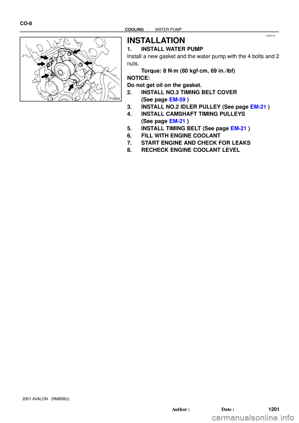
INSTALLATION
1. INSTALL WATER PUMP
Install a new gasket and the water pump with the 4 bolts and 2
nuts.
Torque: 8 N´m (80 kgf´cm, 69 in.´lbf)
NOTICE:
Do not get oil on the gasket.
2. INSTALL NO.3 TIMING BELT COVER
(See page EM-59)
3. INSTALL NO.2 IDLER PULLEY (See page EM-21)
4. INSTALL CAMSHAFT TIMING PULLEYS
(See page EM-21)
5. INSTALL TIMING BELT (See page EM-21)
6. FILL WITH ENGINE COOLANT
7. START ENGINE AND CHECK FOR LEAKS
8. RECHECK ENGINE COOLANT LEVEL
Page 666 of 1897

3")
F07892
ECU ABS
Solenoid
Relay
Brake
Actuator3 Engine Room R/B No. 8
5 25
49 52
6 2650 533 4
54
55
DI-284
- DIAGNOSTICSABS WITH EBD & BA & TRAC & VSC SYSTEM
440 Author�: Date�:
2001 AVALON (RM808U)
3 Check continuity between terminal 3 of engine room R/B No. 8 (for ABS solenoid
relay) and each solenoid terminal of ABS & BA & TRAC & VSC ECU.
PREPARATION:
Disconnect the connector from the ABS & BA & TRAC & VSC
ECU.
CHECK:
Check continuity between terminal 3 of engine room R/B No. 8
and each terminal, 3, 4, 5, 6, 25, 26, 49, 50, 52, 53, 54 and 55
of ECU harness side connector.
OK:
Continuity
HINT:
Resistance of each solenoid coil.
SFLH (5), SRRH (6), SFRH (26), SMC1 (49), SMC2 (50), SRLH
(53): 8 - 9.1 W
SFLR (3), SRRR (4), SRLR (25), SRC2 (52), SRC1 (54), SFRR
(55): 4.0 - 4.6 W
NG Repair or replace harness or brake actuator.
OK
4 Check for open and short circuit in harness and connector between ABS sole-
noid relay and ABS & BA & TRAC & VSC ECU (See page IN-30).
NG Repair or replace harness or connector.
OK
If the same code is still output after the DTC is deleted, check the contact condition of each con-
nection. If the connections are normal, the ECU may be defective.