Page 705 of 1897
F09806
ABS & BA &
TRAC & VSC ECU
A20 E1
EB
T5TC 84
LG-R
4A
4B 4H
4A6
19
196 LG-R
LG-R
LG-R 21
TC Translate ECU
W-B311LG-R D1
DLC1
TC22
II2 3A 3G4 13
LG-R D2
DLC2
E1 TC
4J/B No. 3 J/B No. 4
F10163
DLC2
Tc E
1DLC1
TcON
DI-342
- DIAGNOSTICSABS WITH EBD & BA & TRAC & VSC SYSTEM
498 Author�: Date�:
2001 AVALON (RM808U)
Tc Terminal Circuit
CIRCUIT DESCRIPTION
Connecting between terminals Tc and E1 of the DLC1 or the DLC2 causes the ECU to display DTC by blink-
ing the ABS warning light, VSC warning light and BRAKE warning light.
WIRING DIAGRAM
INSPECTION PROCEDURE
1 Check voltage between terminals Tc and E1.
CHECK:
(a) Turn the ignition switch ON.
(b) Measure the voltage between terminals Tc and E
1 of or
DLC1 or terminal Tc of DLC2 and body ground.
OK:
Voltage: 10 - 14 V
OK If each warning light does not blink even after Tc
and E
1 are connected, the ECU may be defec-
tive.
NG
DI6OO-01
Page 707 of 1897
F09808
ABS & BA &
TRAC & VSC ECU
A20TS 42
LG-B
4A
4B4A J/B No. 4
3
12
12 LG-B
LG-B LG-B
II2 11
16 3TS
D1
DLC1
EBW-B
T524
TS Translate ECU D3
DLC3
E1 TSLG-B LG-B
14
AB0119S08096
F00446
Ts
DLC1Ts
DLC1Ts
DLC1Ts
DLC1Ts
DLC1 ONTs
DLC1 E
1
DI-344
- DIAGNOSTICSABS WITH EBD & BA & TRAC & VSC SYSTEM
500 Author�: Date�:
2001 AVALON (RM808U)
Ts Terminal Circuit
CIRCUIT DESCRIPTION
The sensor check circuit detects abnormality in the speed sensor signal which cannot be detected with the
DTC check.
Connecting terminals Ts and E
1 of the DLC1 starts the check.
WIRING DIAGRAM
INSPECTION PROCEDURE
1 Check voltage between terminals Ts and E1 of DLC1.
CHECK:
(a) Turn the ignition switch ON.
(b) Measure the voltage between terminals Ts and E
1 of
DLC1.
OK:
Voltage: 10 - 14 V
OK If ABS warning light does not blink even after Ts
and E
1 are connected, the ECU may be defec-
tive.
NG
DI6OP-03
Page 712 of 1897
F09820
ABS & BA &
TRAC & VSC ECU
A20
A20CSW
69
J6
J/CWT V8
VSC OFF
Switch
44
Y-RW-L
W-B14 J/B No. 4
4A
4D
4F 4H4F
4D21 8
4 16
16
13 Y-R W-B
Multi Display
M6 M747
R-B
B
BR-B
Driver Side J/B
1G1
1D10
1B3
1C4
34 12 IG1 RelayGAUGE
No. 1
W-R 2
IG1 AM1
4 Ignition Switch
W-L W
IF1 7
W-L
5
5 1 2AM1 Engine Room R/B No. 5
B
2G 2H1
1
B-LW-B
IG II W-B
Battery
FL MAIN
B
F61 F10F81 1
ALT
FL
Block
VSC OFF
Engine Room J/B DI-336
- DIAGNOSTICSABS WITH EBD & BA & TRAC & VSC SYSTEM
492 Author�: Date�:
2001 AVALON (RM808U)
VSC OFF Indicator Light, VSC OFF Switch Circuit
CIRCUIT DESCRIPTION
This is the TRAC & VSC control main switch. When the VSC OFF switch is pressed, TRAC & VSC control
is deactivated and the VSC OFF indicator light lights up. By turning off the ignition switch, TRAC & VSC con-
trol is surely activated when the ignition switch turns ON next time. Also, the VSC OFF indicator light truns
ºONº when the ECU prohibit TRAC & VSC controls.
WIRING DIAGRAM
DI6OM-03
Page 713 of 1897
 (-) 41
- DIAGNOSTICSABS WITH EBD & BA & TRAC & VSC SYSTEM
DI-337
493 Author�: Date�:
2001 AVALON (RM808U)
INSPECTION PROCEDURE
HINT:
Start the inspection from step 1 in case of using the")
F00052
(+) (-) 41
- DIAGNOSTICSABS WITH EBD & BA & TRAC & VSC SYSTEM
DI-337
493 Author�: Date�:
2001 AVALON (RM808U)
INSPECTION PROCEDURE
HINT:
Start the inspection from step 1 in case of using the TOYOTA hand-held tester and start from step 2 in case
of not using the TOYOTA hand-held tester.
1 Check operation of the VSC OFF indicator light.
PREPARATION:
(a) Connect the TOYOTA hand-held tester to the DLC3.
(b) Turn the ignition switch ON and push the TOYOTA hand-held tester main switch ON.
(c) Select the ACTIVE TEST mode on the TOYOTA hand-held tester.
CHECK:
Check that ºONº and ºOFFº of the VSC OFF indicator light can be shown on the combination meter with the
TOYOTA hand-held tester.
NG Go to step 4.
OK
2 Check VSC OFF switch.
PREPARATION:
(a) Remove the VSC OFF switch.
(b) Disconnect the VSC OFF switch connector.
CHECK:
Measure the resistance between terminals 1 and 4 of the VSC
OFF switch when the VSC OFF switch is ON and OFF.
OK:
VSC OFF switchResistance
PressedContinuity
Released1MW or higher
NG Replace VSC OFF switch.
OK
Page 714 of 1897
DI-338
- DIAGNOSTICSABS WITH EBD & BA & TRAC & VSC SYSTEM
494 Author�: Date�:
2001 AVALON (RM808U)
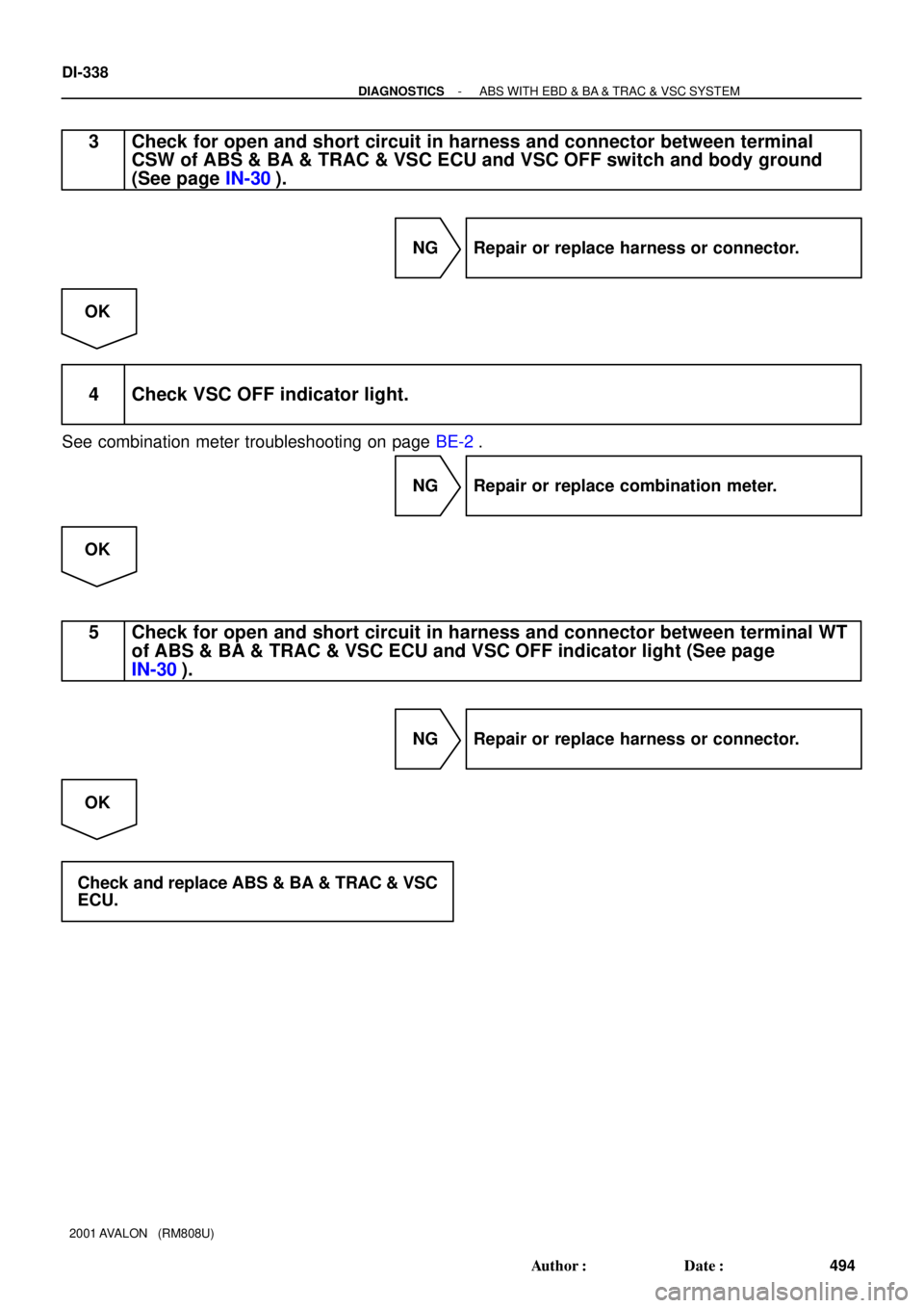
3 Check for open and short circuit in harness and connector between terminal
CSW of ABS & BA & TRAC & VSC ECU and VSC OFF switch and body ground
(See page IN-30).
NG Repair or replace harness or connector.
OK
4 Check VSC OFF indicator light.
See combination meter troubleshooting on page BE-2.
NG Repair or replace combination meter.
OK
5 Check for open and short circuit in harness and connector between terminal WT
of ABS & BA & TRAC & VSC ECU and VSC OFF indicator light (See page
IN-30).
NG Repair or replace harness or connector.
OK
Check and replace ABS & BA & TRAC & VSC
ECU.
Page 715 of 1897
F09818
ABS & BA &
TRAC & VSC ECU
VSCW A2070
P-B
R-B 15
4D
4F 134 4F15
4C P-BJ/B No. 4
M6 M6
R-B4
10 Multi Display
Driver Side J/B
1G1
1D 10
1B3
1C4
3
4 12 IG1 RelayGAUGE
No. 1
W-R 2
IG1 AM1
4 Ignition Switch
W-L W
IF1
7
W-L
5
5 1 2AM1 Engine Room R/B No. 5
B2G 2H11W-B
IG B-L
Battery
FL MAIN
B
F61 F10 F81 1
ALT
FL BlockVSC
Engine Room J/B
- DIAGNOSTICSABS WITH EBD & BA & TRAC & VSC SYSTEM
DI-327
483 Author�: Date�:
2001 AVALON (RM808U)
VSC Warning Light Circuit
CIRCUIT DESCRIPTION
If the ECU stores DTC to be necessary to shut down VSC operation, the VSC warning light lights on the
combination meter.
WIRING DIAGRAM
DI6OJ-03
Page 716 of 1897
DI-328
- DIAGNOSTICSABS WITH EBD & BA & TRAC & VSC SYSTEM
484 Author�: Date�:
2001 AVALON (RM808U)
INSPECTION PROCEDURE
HINT:
Start the inspection from step 1 in case of using the TOYOTA hand-held tester and start from step 2 in case
of not using the TOYOTA hand-held tester.
1 Check operation of the VSC warning light.
PREPARATION:
(a) Connect the TOYOTA hand-held tester to the DLC3.
(b) Turn the ignition switch ON and push the TOYOTA hand-held tester main switch ON.
(c) Select the ACTIVE TEST mode on the TOYOTA hand-held tester.
CHECK:
Check that ºONº and ºOFFº of the VSC warning light can be shown on the combination meter with the TOYO-
TA hand-held tester.
OK Check and replace ABS & BA & TRAC & VSC
ECU.
NG
2 Is DTC output?
YES Repair circuit indicated by the output code.
NO
3 Check for open and short circuit in harness and connector between ABS & BA &
TRAC & VSC ECU and VSC warning light (See page IN-30).
NG Repair or replace harness or connector.
OK
Page 717 of 1897
- DIAGNOSTICSABS WITH EBD & BA & TRAC & VSC SYSTEM
DI-329
485 Author�: Date�:
2001 AVALON (RM808U)
4 Check VSC warning light.
See the combination meter troubleshooting on page BE-2.
NG Repair or replace combination meter.
OK
Check and replace ABS & BA & TRAC & VSC
ECU.