Page 952 of 1897
- DIAGNOSTICSENGINE
DI-73
229 Author�: Date�:
2001 AVALON (RM808U)
3 Check A/F sensor (bank 1, 2 sensor 1) (See page SF-79).
NG Repair or replace.
OK
4 Check heated oxygen sensor (bank 1 sensor 2) (See page SF-81).
NG Repair or replace.
OK
Replace three-way catalytic converter (See
page EC-15).
Page 1030 of 1897

DI07B-20
DI-14
- DIAGNOSTICSENGINE
170 Author�: Date�:
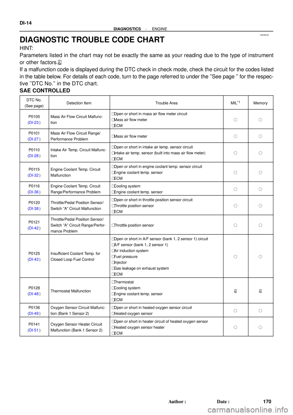
DIAGNOSTIC TROUBLE CODE CHART
HINT:
Parameters listed in the chart may not be exactly the same as your reading due to the type of instrument
or other factors.
If a malfunction code is displayed during the DTC check in check mode, check the circuit for the codes listed
in the table below. For details of each code, turn to the page referred to under the ''See page '' for the respec-
tive ''DTC No.'' in the DTC chart.
SAE CONTROLLED
DTC No.
(See page)Detection ItemTrouble AreaMIL*1Memory
P0100
(DI-23)Mass Air Flow Circuit Malfunc-
tion�Open or short in mass air flow meter circuit
�Mass air flow meter
�ECM
��
P0101
(DI-27)Mass Air Flow Circuit Range/
Performance Problem�Mass air flow meter��
P0110
(DI-28)Intake Air Temp. Circuit Malfunc-
tion�Open or short in intake air temp. sensor circuit
�Intake air temp. sensor (built into mass air flow meter)
�ECM
��
P0115
(DI-32)Engine Coolant Temp. Circuit
Malfunction�Open or short in engine coolant temp. sensor circuit
�Engine coolant temp. sensor
�ECM
��
P0116
(DI-36)Engine Coolant Temp. Circuit
Range/Performance Problem�Cooling system
�Engine coolant temp. sensor��
P0120
(DI-38)Throttle/Pedal Position Sensor/
Switch ºAº Circuit Malfunction�Open or short in throttle position sensor circuit
�Throttle position sensor
�ECM
��
P0121
(DI-42)Throttle/Pedal Position Sensor/
Switch ºAº Circuit Range/Perfor-
mance Problem
�Throttle position sensor��
P0125
(DI-43)Insufficient Coolant Temp. for
Closed Loop Fuel Control
�Open or short in A/F sensor (bank 1, 2 sensor 1) circuit
�A/F sensor (bank 1, 2 sensor 1)
�Air induction system
�Fuel pressure
�Injector
�Gas leakage on exhaust system
�ECM
��
P0128
(DI-48)Thermostat Malfunction
�Thermostat
�Cooling system
�Engine coolant temp. sensor
�ECM
P0136
(DI-49)Oxygen Sensor Circuit Malfunc-
tion (Bank 1 Sensor 2)�Open or short in heated oxygen sensor circuit
�Heated oxygen sensor��
P0141
(DI-51)Oxygen Sensor Heater Circuit
Malfunction (Bank 1 Sensor 2)�Open or short in heater circuit of heated oxygen sensor
�Heated oxygen sensor heater
�ECM
��
Page 1031 of 1897

- DIAGNOSTICSENGINE
DI-15
171 Author�: Date�:
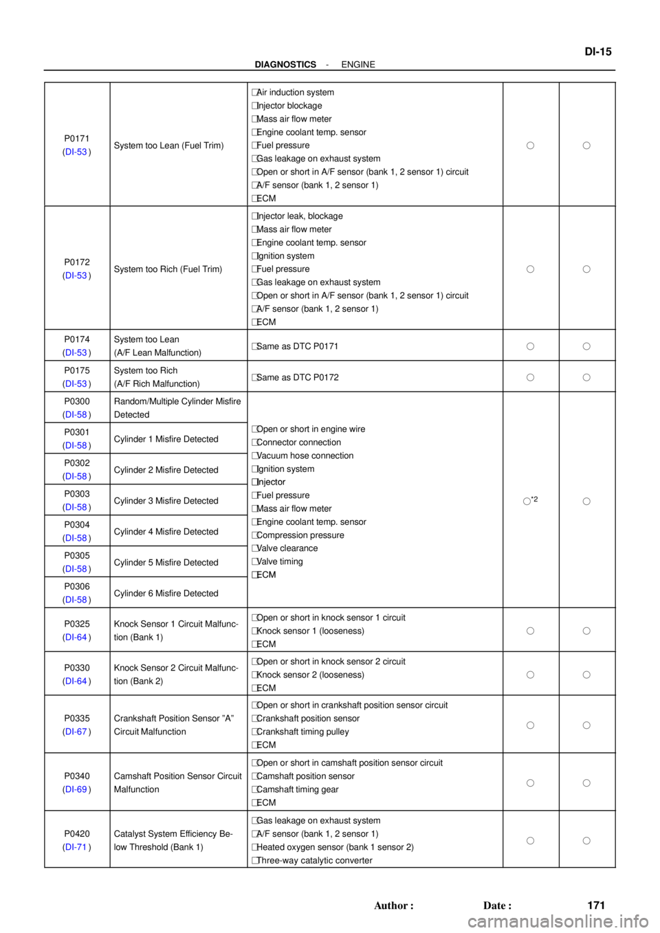
P0171
(DI-53)System too Lean (Fuel Trim)
�Air induction system
�Injector blockage
�Mass air flow meter
�Engine coolant temp. sensor
�Fuel pressure
�Gas leakage on exhaust system
�Open or short in A/F sensor (bank 1, 2 sensor 1) circuit
�A/F sensor (bank 1, 2 sensor 1)
�ECM
��
P0172
(DI-53)System too Rich (Fuel Trim)
�Injector leak, blockage
�Mass air flow meter
�Engine coolant temp. sensor
�Ignition system
�Fuel pressure
�Gas leakage on exhaust system
�Open or short in A/F sensor (bank 1, 2 sensor 1) circuit
�A/F sensor (bank 1, 2 sensor 1)
�ECM
��
P0174
(DI-53)System too Lean
(A/F Lean Malfunction)�Same as DTC P0171��
P0175
(DI-53)System too Rich
(A/F Rich Malfunction)�Same as DTC P0172��
P0300
(DI-58)Random/Multiple Cylinder Misfire
Detected
P0301
(DI-58)Cylinder 1 Misfire Detected�Open or short in engine wire
�Connector connection
Vh tiP0302
(DI-58)Cylinder 2 Misfire Detected
�Vacuum hose connection
�Ignition system
�
Injector
P0303
(DI-58)Cylinder 3 Misfire Detected
�Injector
�Fuel pressure
�Mass air flow meter
�*2�
P0304
(DI-58)Cylinder 4 Misfire Detected
Mass air flow meter
�Engine coolant temp. sensor
�Compression pressure
Vl lP0305
(DI-58)Cylinder 5 Misfire Detected
�Valve clearance
�Valve timing
�
ECM
P0306
(DI-58)Cylinder 6 Misfire Detected
�ECM
P0325
(DI-64)Knock Sensor 1 Circuit Malfunc-
tion (Bank 1)�Open or short in knock sensor 1 circuit
�Knock sensor 1 (looseness)
�ECM
��
P0330
(DI-64)Knock Sensor 2 Circuit Malfunc-
tion (Bank 2)�Open or short in knock sensor 2 circuit
�Knock sensor 2 (looseness)
�ECM
��
P0335
(DI-67)Crankshaft Position Sensor ºAº
Circuit Malfunction
�Open or short in crankshaft position sensor circuit
�Crankshaft position sensor
�Crankshaft timing pulley
�ECM
��
P0340
(DI-69)Camshaft Position Sensor Circuit
Malfunction
�Open or short in camshaft position sensor circuit
�Camshaft position sensor
�Camshaft timing gear
�ECM
��
P0420
(DI-71)Catalyst System Efficiency Be-
low Threshold (Bank 1)
�Gas leakage on exhaust system
�A/F sensor (bank 1, 2 sensor 1)
�Heated oxygen sensor (bank 1 sensor 2)
�Three-way catalytic converter
��
Page 1036 of 1897
DI07C-09
A11424
Knock Sensor 1 DLC1
IAC Valve VSV for EVAP
Engine Coolant
Temp. Sensor
Injector
Crankshaft Position
Sensor
A/F Sensor
(Bank 2 Sensor 1)Park/Neutral Position SwitchDLC3 ECM
Heated Oxygen Sensor
(Bank 1 Sensor 2)
VVT Sensor
(Bank 2)VVT Sensor (Bank 1)
OCV (Bank 2)OCV (Bank 1)
Canister
Vapor Pressure Sensor A/F Sensor
(Bank 1 Sensor 1)
VSV for Pressure Switching Valve VSV for CCV
Ignition Coil
with lgniter
Mass Air Flow Meter
Throttle Position Sensor
Combination Meter
VSV for
No.1 ACIS
VSV for
No.2 ACIS
Knock Sensor 2
- DIAGNOSTICSENGINE
DI-19
175 Author�: Date�:
2001 AVALON (RM808U)
PARTS LOCATION
Page 1046 of 1897

DI-12
- DIAGNOSTICSENGINE
168 Author�: Date�:
2001 AVALON (RM808U)SHORT FT #2
Short-term Fuel Trim Bank 20 ± 20 %
LONG FT #2Long-term Fuel Trim Bank 20 ± 20 %
ENGINE SPDEngine SpeedIdling: 650 - 750 rpm
VEHICLE SPDVehicle SpeedVehicle stopped: 0 km/h (0 mph)
IGN ADVANCEIgnition Advance: Ignition Timing of Cylinder No.1Idling: BTDC 10 - 25.0°
INTAKE AIRIntake Air Temp. Sensor ValueEquivalent to Ambient Temp.
MAFAir Flow Rate Through Mass Air Flow Meter
Idling: 3.3 - 4.7 gm/sec.
Racing without load (2,500 rpm):
10.4 - 15.4 gm/sec.
THROTTLE POSVoltage Output of Throttle Position Sensor Calcu-
lated as a percentage: 0 V "0 %, 5 V "100 %Throttle valve fully closed: 7 - 11 %
Throttle valve fully open: 65 - 75 %
O2FT B1 S1Oxygen Sensor Fuel Trim Bank 1 Sensor 1
(Same as SHORT FT #1)0 ± 20 %
O2S B1 S2Voltage Output of Oxygen Sensor Bank 1 Sensor
2Driving 50 km/h (31 mph): 0.05 - 0.95 V
O2FT B2 S1Oxygen Sensor Fuel Trim Bank 2 Sensor 1
(Same as SHORT FT #2)0 ± 20 %
A/FS B1 S1Voltage Output of A/F Sensor Bank 1 Sensor 1Idling: 2.8 - 3.8 V
A/FS B2 S1Voltage Output of A/F Sensor Bank 2 Sensor 1Idling: 2.8 - 3.8 V
A/FFT B1 S1A/F Sensor Fuel Trim Bank 1 Sensor 1
(Same as SHORT FT #1)0 ± 20 %
A/FFT B2 S1A/F Sensor Fuel Trim Bank 2 Sensor 1
(Same as SHORT FT #1)0 ± 20 %
*: If no conditions are specifically stated for ºldlingº, it means the shift lever is at N or P position, the A/C switch
is OFF and all accessory switches are OFF.
(b) TOYOTA Enhanced Signals.
TOYOTA hand-held tester displayMeasurement ItemNormal Condition*
MISFIRE RPMEngine RPM for first misfire rangeMisfire 0: 0 rpm
MISFIRE LOADEngine load for first misfire rangeMisfire 0: 0 g/r
INJECTORFuel injection time for cylinder No.1Idling: 1.6 - 2.9 ms
IAC DUTY RATIOIntake Air Control Valve Duty Ratio
Opening ratio rotary solenoid type IAC valveIdling: 27 - 47 %
STARTER SIGStarter SignalCranking: ON
CTP SIGClosed Throttle Position SignalThrottle fully closed: ON
A/C SIGA/C Switch SignalA/C ON: ON
PNP SWPark/Neutral Position Switch SignalP or N position: ON
ELCTRCL LOAD SIGElectrical Load SignalDefogger switch ON: ON
STOP LIGHT SWStop Light Switch SignalStop light switch ON: ON
PS OIL PRESS SWPower Steering Oil Pressure Switch SignalTurn steering wheel: ON
FC IDLFuel Cut Idle: Fuel cut when throttle valve fully
closed, during decelerationFuel cut operating: ON
FC TAUFuel Cut TAU: Fuel cut during very light loadFuel cut operating: ON
CYL#1 - CYL#6Abnormal revolution variation for each cylinder0 %
IGNITIONTotal number of ignition for every 1,000 revolu-
tions0 - 3,000
INTAKE CTRL VSVIntake Air Control Valve VSV SignalVSV operating: ON
A/C CUT SIGA/C Cut SignalA/C S/W OFF: ON
FUEL PUMPFuel Pump SignalIdling: ON
Page 1279 of 1897
EC01J-03
B08913
Vapor
Pressure
Sensor
A/F Sensor
(Bank 2 Sensor 1)A/F Sensor
(Bank 1 Sensor 1)
TWCVSV for EVAP
Fuel Tank
Charcoal
Canister
WU-TWCHeated Oxygen Sensor
(Bank 1 Sensor 2)
WU-TWC
EVAP Service Port
Purge Line
Air Inlet Line Air Drain
HoseEVAP Line
Vent Line
VSV for Canister
Closed Valve (CCV) VSV for Pressure
Switching Valve
Air Cleaner
- EMISSION CONTROLPARTS LAYOUT AND SCHEMATIC DRAWING
EC-3
1097 Author�: Date�:
2001 AVALON (RM808U)
DRAWING
Page 1281 of 1897
EC04T-03
B07459
N´m (kgf´cm, ft´lbf) : Specified torque
� Non-reusable part� Gasket
44 (450, 33)
Damper � Gasket
43 (440, 32)
TWC
Compression Spring
Center Exhaust PipeCompression Spring
43 (440, 32)
Heated Oxygen Sensor
(Bank 1 Sensor 2)
Heated Oxygen Sensor (Bank 1 Sensor 2)
HINT:
� Before installing the heated oxygen sensor,
twist the sensor wire counterclockwise
3 and 1/2 turns.
� After installing the heated oxygen sensor,
check that the sensor wire is not twisted,
if it is twisted, remove the heated oxygen
sensor and reinstall it.
- EMISSION CONTROLTHREE-W AY CATALYTIC CONVERTER (TWC)
SYSTEMEC-15
1109 Author�: Date�:
2001 AVALON (RM808U)
COMPONENTS
Page 1373 of 1897
EM0ZR-02
A10836
� Gasket
� Non-reusable part
N´m (kgf´cm, ft´lbf) : Specified torque� Gasket
� Bracket
Front Exhaust Pipe Heat Insulator
Center Exhaust Pipe� Gasket Heat Insulator
Heated Oxygen Sensor
(Bank 1 Sensor 2)Tailpipe
Ring Ring
33 (330, 24)
Heat Insulator Heated Oxygen Sensor (Bank 1 Sensor 2)
� Before installing the oxygen sensor, twist
the sensor wire counterclockwise 3 and
1/2 turns.
If it is twisted, remove the oxygen sensor
and reinstall it. � After installing the sensor wire is not twisted.HINT:
43 (440, 32)
21 (210, 15)
62 (630, 46)
33 (330, 24)
44 (450, 33)
Stay
Pipe Support
Bracket
39 (400, 29)
22 (220,16)
Pipe Support
Bracket
33 (330, 24)
�62 (630, 46)
43 (440, 32)
Compression Spring
�
�
Compression Spring
Damper
19 (190, 14)
Heat Insulator
No.1 Exhaust Pipe
Support Bracket
Type A
Type B
Ring
Pipe Support
Bracket
EM-1 10
- ENGINE MECHANICALEXHAUST SYSTEM
1094 Author�: Date�:
2001 AVALON (RM808U)
EXHAUST SYSTEM
COMPONENTS