Page 1125 of 1897
H01022
H02146AB0119H04524
P SquibAirbag
Sensor
Assembly
(-) (+)P+
ON
- DIAGNOSTICSSUPPLEMENTAL RESTRAINT SYSTEM
DI-389
545 Author�: Date�:
2001 AVALON (RM808U)
DTC B0108/52 Short in P Squib Circuit (to B+)
CIRCUIT DESCRIPTION
The P squib circuit consists of the airbag sensor assembly and front passenger airbag assembly.
It causes the SRS to deploy when the SRS deployment conditions are satisfied.
For details of the function of each component, see OPERATION on page RS-3.
DTC B0108/52 is recorded when a B+ short is detected in the P squib circuit.
DTC No.DTC Detecting ConditionTrouble Area
B0108/52
�Short circuit in P squib wire harness (to B+)
�P squib malfunction
�Airbag sensor assembly malfunction�Front passenger airbag assembly (P squib)
�Airbag sensor assembly
�Wire harness
WIRING DIAGRAM
See page DI-379.
INSPECTION PROCEDURE
1 Prepare for inspection (See step 1 on page DI-475).
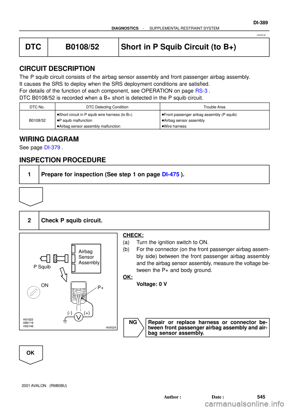
2 Check P squib circuit.
CHECK:
(a) Turn the ignition switch to ON.
(b) For the connector (on the front passenger airbag assem-
bly side) between the front passenger airbag assembly
and the airbag sensor assembly, measure the voltage be-
tween the P+ and body ground.
OK:
Voltage: 0 V
NG Repair or replace harness or connector be-
tween front passenger airbag assembly and air-
bag sensor assembly.
OK
DI4CR-02
Page 1128 of 1897
H01454
Side Squib (RH)Airbag Sensor Assembly
FR+
FR- Y-R
Y-G 1
21 2
C7
C7 DI-392
- DIAGNOSTICSSUPPLEMENTAL RESTRAINT SYSTEM
548 Author�: Date�:
2001 AVALON (RM808U)
DTC B0110/43 Short in Side Squib (RH) Circuit
CIRCUIT DESCRIPTION
The side squib (RH) circuit consists of the airbag sensor assembly and side airbag assembly (RH).
It causes the SRS to deploy when the SRS deployment conditions are satisfied.
For details of the function of each component, see OPERATION on page RS-3.
DTC B0110/43 is recorded when a short is detected in the side squib (RH) circuit.
DTC No.DTC Detecting ConditionTrouble Area
B0110/43
�Short circuit between FR+ wire harness and FR- wire
harness of squib
�Side squib (RH) malfunction
�Airbag sensor assembly malfunction�Side airbag assembly (RH)
�Airbag sensor assembly
�Wire harness
WIRING DIAGRAM
DI6MS-01
Page 1132 of 1897
H01019H09668H12947
Squib (RH)Airbag
Sensor
Assembly
(-) (+)
FR+ FR-
DI-396
- DIAGNOSTICSSUPPLEMENTAL RESTRAINT SYSTEM
552 Author�: Date�:
2001 AVALON (RM808U)
DTC B0111/44 Open in Side Squib (RH) Circuit
CIRCUIT DESCRIPTION
The side squib (RH) circuit consists of the airbag sensor assembly and side airbag assembly (RH).
It causes the SRS to deploy when the SRS deployment conditions are satisfied.
For details of the function of each component, see OPERATION on page RS-3.
DTC B0111/44 is recorded when an open is detected in the side squib (RH) circuit.
DTC No.DTC Detecting ConditionTrouble Area
B0111/44
�Open circuit in FR+ wire harness or FR- wire harness of
squib
�Side squib (RH) malfunction
�Airbag sensor assembly malfunction�Side airbag assembly (RH)
�Airbag sensor assembly
�Wire harness
WIRING DIAGRAM
See page DI-392.
INSPECTION PROCEDURE
1 Prepare for inspection (See step 1 on page DI-475).
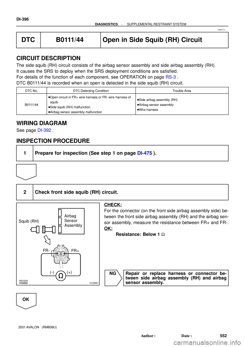
2 Check front side squib (RH) circuit.
CHECK:
For the connector (on the front side airbag assembly side) be-
tween the front side airbag assembly (RH) and the airbag sen-
sor assembly, measure the resistance between FR+ and FR-.
OK:
Resistance: Below 1 W
NG Repair or replace harness or connector be-
tween side airbag assembly (RH) and airbag
sensor assembly.
OK
DI6MT-01
Page 1135 of 1897
H01019H09669H12949
Airbag
Sensor
Assembly Squib (RH)
(+)FR+
(-)
- DIAGNOSTICSSUPPLEMENTAL RESTRAINT SYSTEM
DI-399
555 Author�: Date�:
2001 AVALON (RM808U)
DTC B0112/41 Short in Side Squib (RH) Circuit (to
Ground)
CIRCUIT DESCRIPTION
The side squib (RH) circuit consists of the airbag sensor assembly and side airbag assembly (RH).
It causes the SRS to deploy when the SRS deployment conditions are satisfied.
For details of the function of each component, see OPERATION on page RS-3.
DTC B0112/41 is recorded when ground short is detected in the side squib (RH) circuit.
DTC No.DTC Detecting ConditionTrouble Area
B0112/41
�Short circuit in side squib (RH) wire harness (to ground)
�Side squib (RH) malfunction
�Airbag sensor assembly malfunction�Side airbag assembly (RH)
�Airbag sensor assembly
�Wire harness
WIRING DIAGRAM
See page DI-392.
INSPECTION PROCEDURE
1 Prepare for inspection (See step 1 on page DI-475).
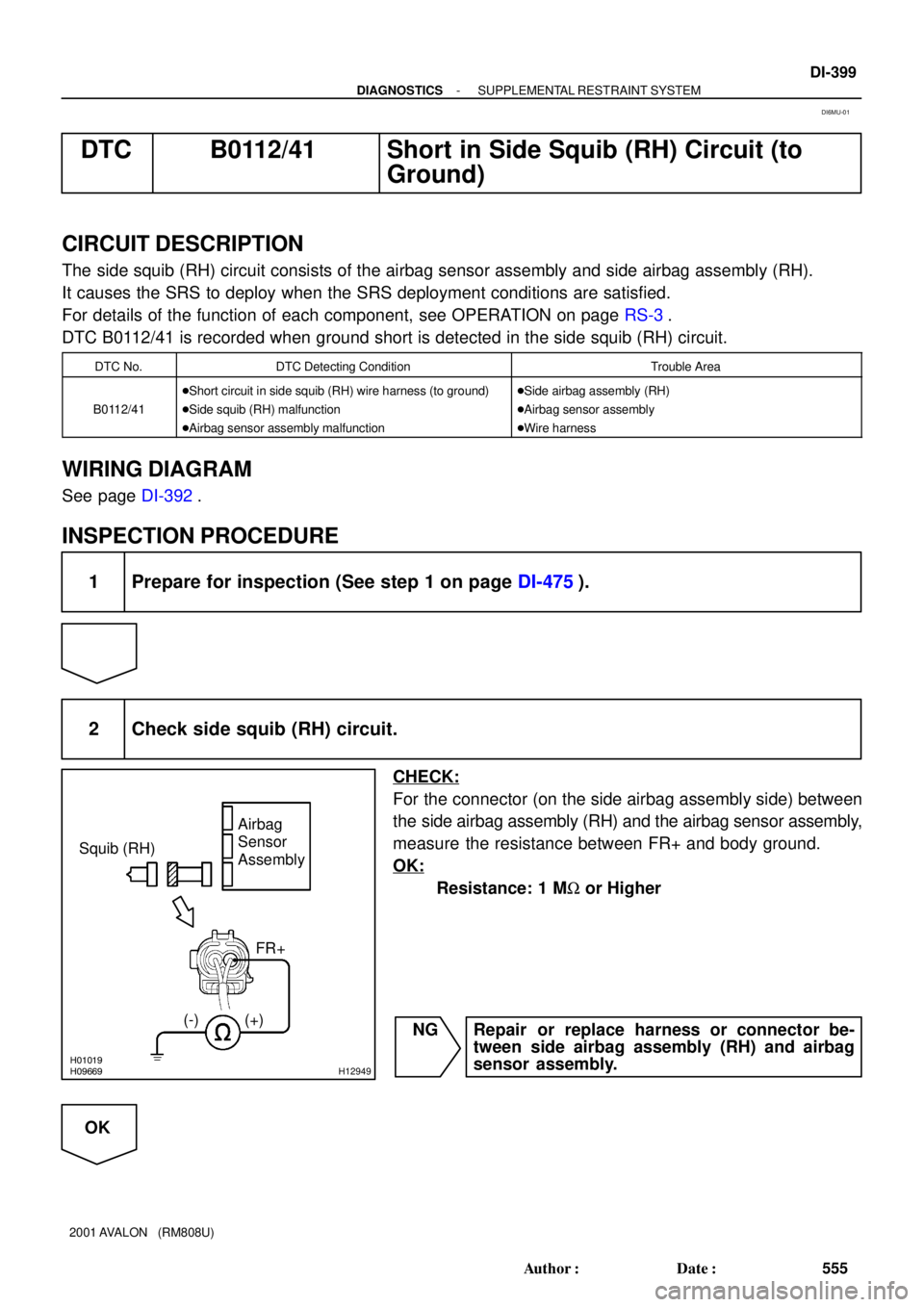
2 Check side squib (RH) circuit.
CHECK:
For the connector (on the side airbag assembly side) between
the side airbag assembly (RH) and the airbag sensor assembly,
measure the resistance between FR+ and body ground.
OK:
Resistance: 1 MW or Higher
NG Repair or replace harness or connector be-
tween side airbag assembly (RH) and airbag
sensor assembly.
OK
DI6MU-01
Page 1138 of 1897
H01019AB0119
H09670H12951
Squib (RH)Airbag
Sensor
Assembly
(-)(+)FR+
ON
DI-402
- DIAGNOSTICSSUPPLEMENTAL RESTRAINT SYSTEM
558 Author�: Date�:
2001 AVALON (RM808U)
DTC B0113/42 Short in Side Squib (RH) Circuit (to B+)
CIRCUIT DESCRIPTION
The side squib (RH) circuit consists of the airbag sensor assembly and side airbag assembly (RH).
It causes the SRS to deploy when the SRS deployment conditions are satisfied.
For details of the function of each component, see OPERATION on page RS-3.
DTC B0113/42 is recorded when a B+ short is detected in the side squib (RH) circuit.
DTC No.DTC Detecting ConditionTrouble Area
B0113/42
�Short circuit in side squib (RH) wire harness (to B+)
�Side squib (RH) malfunction
�Airbag sensor assembly malfunction�Side airbag assembly (RH)
�Airbag sensor assembly
�Wire harness
WIRING DIAGRAM
See page DI-392.
INSPECTION PROCEDURE
1 Prepare for inspection (See step 1 on page DI-349).
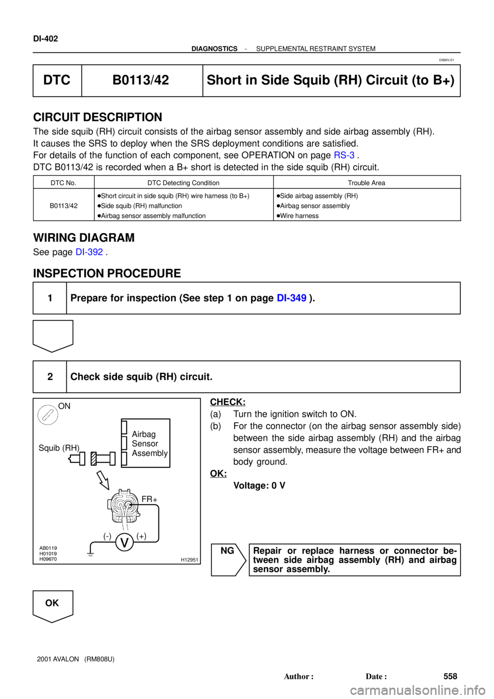
2 Check side squib (RH) circuit.
CHECK:
(a) Turn the ignition switch to ON.
(b) For the connector (on the airbag sensor assembly side)
between the side airbag assembly (RH) and the airbag
sensor assembly, measure the voltage between FR+ and
body ground.
OK:
Voltage: 0 V
NG Repair or replace harness or connector be-
tween side airbag assembly (RH) and airbag
sensor assembly.
OK
DI6MV-01
Page 1141 of 1897
H01454
Side Squib (LH)Airbag Sensor Assembly
FL+
FL- Y-R
Y-G 1
26 5
C5
C5
- DIAGNOSTICSSUPPLEMENTAL RESTRAINT SYSTEM
DI-405
561 Author�: Date�:
2001 AVALON (RM808U)
DTC B0115/47 Short in Side Squib (LH) Circuit
CIRCUIT DESCRIPTION
The side squib (LH) circuit consists of the airbag sensor assembly and side airbag assembly (LH).
It causes the SRS to deploy when the SRS deployment conditions are satisfied.
For details of the function of each component, see OPERATION on page RS-3.
DTC B0115/47 is recorded when a short is detected in the side squib (LH) circuit.
DTC No.DTC Detecting ConditionTrouble Area
B0115/47
�Short circuit between FL+ wire harness and FL- wire har-
ness of squib
�Side squib (LH) malfunction
�Airbag sensor assembly malfunction�Side airbag assembly (LH)
�Airbag sensor assembly
�Wire harness
WIRING DIAGRAM
DI6MW-01
Page 1145 of 1897
H01019H09668H12954
Squib (LH)Airbag
Sensor
Assembly
(-) (+)
FL-FL+
- DIAGNOSTICSSUPPLEMENTAL RESTRAINT SYSTEM
DI-409
565 Author�: Date�:
2001 AVALON (RM808U)
DTC B0116/48 Open in Side Squib (LH) Circuit
CIRCUIT DESCRIPTION
The side squib (LH) circuit consists of the airbag sensor assembly and side airbag assembly (LH).
It causes the SRS to deploy when the SRS deployment conditions are satisfied.
For details of the function of each component, see OPERATION on page RS-3.
DTC B0116/48 is recorded when an open is detected in the side squib (LH) circuit.
DTC No.DTC Detecting ConditionTrouble Area
B0116/48
�Open circuit in FL+ wire harness or FL- wire harness of
squib
�Side squib (LH) malfunction
�Airbag sensor assembly malfunction�Side airbag assembly (LH)
�Airbag sensor assembly
�Wire harness
WIRING DIAGRAM
See page DI-405.
INSPECTION PROCEDURE
1 Prepare for inspection. (See step 1 on page DI-475)
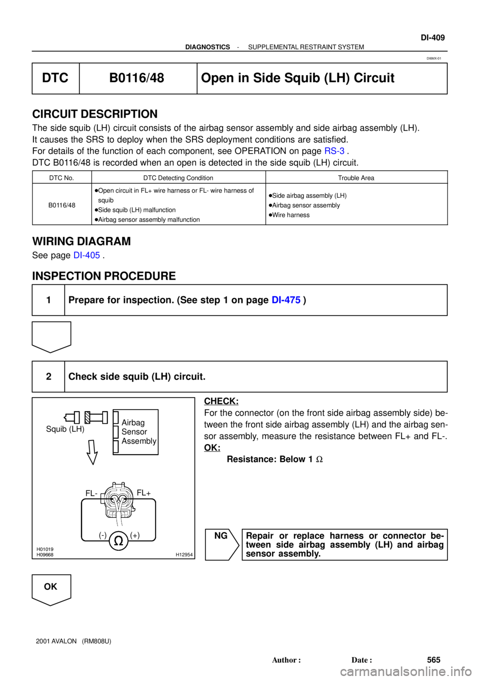
2 Check side squib (LH) circuit.
CHECK:
For the connector (on the front side airbag assembly side) be-
tween the front side airbag assembly (LH) and the airbag sen-
sor assembly, measure the resistance between FL+ and FL-.
OK:
Resistance: Below 1 W
NG Repair or replace harness or connector be-
tween side airbag assembly (LH) and airbag
sensor assembly.
OK
DI6MX-01
Page 1148 of 1897
H01016H09669H12956
Squib (LH)
Airbag
Sensor
Assembly
(-) (+)
FL+
DI-412
- DIAGNOSTICSSUPPLEMENTAL RESTRAINT SYSTEM
568 Author�: Date�:
2001 AVALON (RM808U)
DTC B0117/45 Short in Side Squib (LH) Circuit (to
Ground)
CIRCUIT DESCRIPTION
The side squib (LH) circuit consists of the airbag sensor assembly and side airbag assembly (LH).
It causes the SRS to deploy when the SRS deployment conditions are satisfied.
For details of the function of each component, see OPERATION on page RS-3.
DTC B0117/45 is recorded when ground short is detected in the side squib (LH) circuit.
DTC No.DTC Detecting ConditionTrouble Area
B0117/45
�Short circuit in side squib (LH) wire harness (to ground)
�Side squib (LH) malfunction
�Airbag sensor assembly malfunction�Side airbag assembly (LH)
�Airbag sensor assembly
�Wire harness
WIRING DIAGRAM
See page DI-405.
INSPECTION PROCEDURE
1 Prepare for inspection (See step 1 on page DI-475).
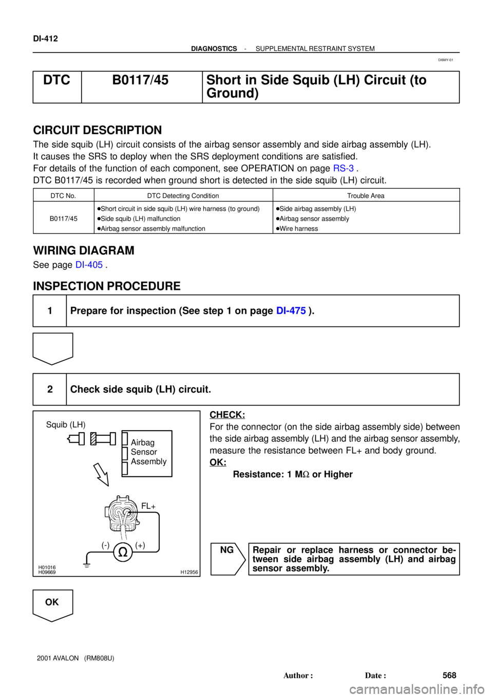
2 Check side squib (LH) circuit.
CHECK:
For the connector (on the side airbag assembly side) between
the side airbag assembly (LH) and the airbag sensor assembly,
measure the resistance between FL+ and body ground.
OK:
Resistance: 1 MW or Higher
NG Repair or replace harness or connector be-
tween side airbag assembly (LH) and airbag
sensor assembly.
OK
DI6MY-01