Page 1090 of 1897

I13621
Seat Memory SwitchPower Seat ECU
SWE SW2
MMRY 21
320
9SW1
7 1 4
2
P21 P21 P21
P21
2
1
MMRY
EY
G-W
G-Y
W-B
S14
I11616
(+)
(-)9 (MMRY)
19 (SGND)
20 (SW2) 21 (SW1)
- DIAGNOSTICSPOWER SEAT CONTROL SYSTEM (w/ Driving Position
Memory)DI-513
669 Author�: Date�:
2001 AVALON (RM808U)
Seat Memory Switch
CIRCUIT DESCRIPTION
Seat memory switch send memory and return signals to the seat position control ECU.
WIRING DIAGRAM
INSPECTION PROCEDURE
1 Check voltage between each terminal of the seat memory switch and SGND of
Seat Position Control ECU connector.
PREPARATION:
Remove Seat Position Control ECU with connectors still con-
nected.
CHECK:
Measure voltage between terminal of the seat memory switch
and SGND of Seat Position Control ECU connector.
(The illustration shows inspection of the Memory 1 as an exam-
ple.)
OK:
At each terminal with switch ON0 V
At each terminal with switch OFF10 ~ 14 V
OK Proceed to next circuit inspection shown in
problem symptom table (See page DI-493).
DI0GH-06
Page 1098 of 1897
DI4CK-03
H01451
Y-B
D+ C6 14Airbag Sensor Assembly
13
C6D- Y 1
2
Spiral
Cable D Squib DI-362
- DIAGNOSTICSSUPPLEMENTAL RESTRAINT SYSTEM
518 Author�: Date�:
2001 AVALON (RM808U)
CIRCUIT INSPECTION
DTC B0100/13 Short in D Squib Circuit
CIRCUIT DESCRIPTION
The D squib circuit consists of the airbag sensor assembly, spiral cable and steering wheel pad.
It causes the airbag to deploy when the airbag deployment conditions are satisfied.
For details of the function of each component, see OPERATION on page RS-3.
DTC B0100/13 is recorded when a short is detected in the D squib circuit.
DTC No.DTC Detecting ConditionTrouble Area
B0100/13
�Short circuit between D+ wire harness and D- wire har-
ness of squib
�D squib malfunction
�Spiral cable malfunction
�Airbag sensor assembly malfunction�Steering wheel pad (D squib)
�Spiral cable
�Airbag sensor assembly
�Wire harness
WIRING DIAGRAM
Page 1103 of 1897
R14286H01001H01139
D SquibSpiral
Cable
Airbag
Sensor
Assembly
D+ u"
(-) (+)D-
- DIAGNOSTICSSUPPLEMENTAL RESTRAINT SYSTEM
DI-367
523 Author�: Date�:
2001 AVALON (RM808U)
DTC B0101/14 Open in D Squib Circuit
CIRCUIT DESCRIPTION
The D squib circuit consists of the airbag sensor assembly, spiral cable and steering wheel pad.
It causes the airbag to deploy when the airbag deployment conditions are satisfied.
For details of the function of each components, see OPERATION on page RS-3.
DTC B0101/14 is recorded when an open is detected in the D squib circuit.
DTC No.DTC Detecting ConditionTrouble Area
B0101/14
�Open circuit in D+ wire harness or D- wire harness of
squib
�D squib malfunction
�Spiral cable malfunction
�Airbag sensor assembly malfunction�Steering wheel pad (D squib)
�Spiral cable
�Airbag sensor assembly
�Wire harness
WIRING DIAGRAM
See page DI-362.
INSPECTION PROCEDURE
1 Prepare for inspection. (See step 1 on page DI-475)
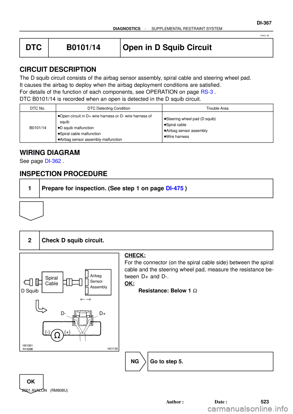
2 Check D squib circuit.
CHECK:
For the connector (on the spiral cable side) between the spiral
cable and the steering wheel pad, measure the resistance be-
tween D+ and D-.
OK:
Resistance: Below 1 W
NG Go to step 5.
OK
DI4CL-02
Page 1107 of 1897
H01001H02145H02198
D SquibSpiral
Cable
Airbag
Sensor
Assembly
D+
(-) (+)
- DIAGNOSTICSSUPPLEMENTAL RESTRAINT SYSTEM
DI-371
527 Author�: Date�:
2001 AVALON (RM808U)
DTC B0102/11 Short in D Squib Circuit (to Ground)
CIRCUIT DESCRIPTION
The D squib circuit consists of the airbag sensor assembly, spiral cable and steering wheel pad.
It causes the SRS to deploy when the SRS deployment conditions are satisfied.
For details of the function of each component, see OPERATION on page RS-3.
DTC B0102/11 is recorded when a ground short is detected in the D squib circuit.
DTC No.DTC Detecting ConditionTrouble Area
B0102/11
�Short circuit in D squib wire harness (to ground)
�D squib malfunction
�Spiral cable malfunction
�Airbag sensor assembly malfunction�Steering wheel pad (D squib)
�Spiral cable
�Airbag sensor assembly
�Wire harness
WIRING DIAGRAM
See page DI-362.
INSPECTION PROCEDURE
1 Prepare for inspection (See step 1 on page DI-475).
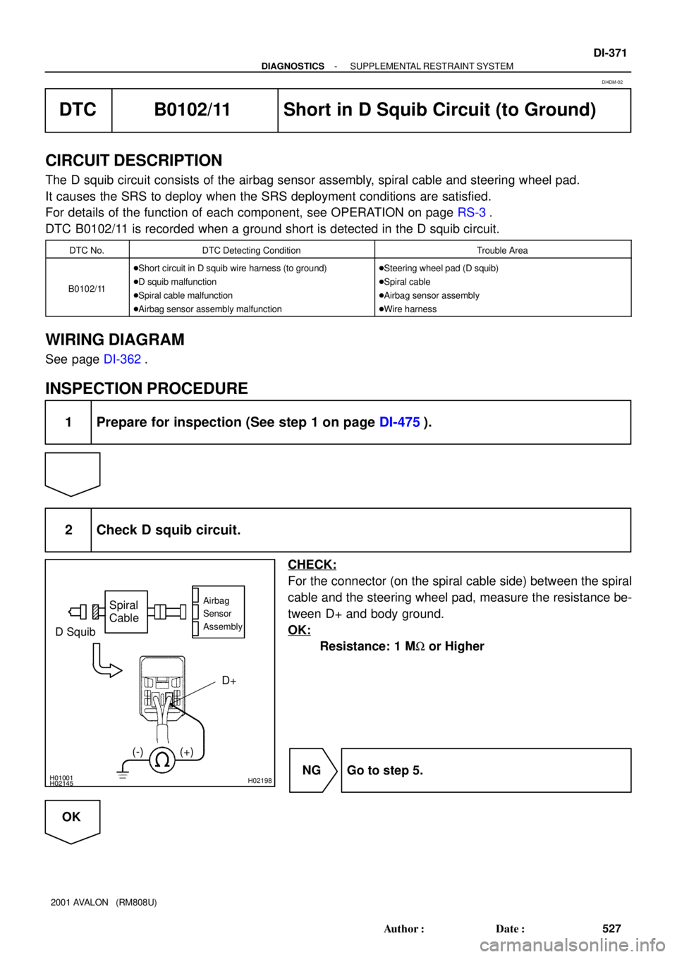
2 Check D squib circuit.
CHECK:
For the connector (on the spiral cable side) between the spiral
cable and the steering wheel pad, measure the resistance be-
tween D+ and body ground.
OK:
Resistance: 1 MW or Higher
NG Go to step 5.
OK
DI4DM-02
Page 1111 of 1897
H01001H02146
AB0119
H11570
D SquibSpiral
Cable
Airbag
Sensor
Assembly
D+
(-) (+)
ON
- DIAGNOSTICSSUPPLEMENTAL RESTRAINT SYSTEM
DI-375
531 Author�: Date�:
2001 AVALON (RM808U)
DTC B0103/12 Short in D Squib Circuit (to B+)
CIRCUIT DESCRIPTION
The D squib circuit consists of the airbag sensor assembly, spiral cable and steering wheel pad.
It causes the SRS to deploy when the SRS deployment conditions are satisfied.
For details of the function of each component, see OPERATION on page RS-3.
DTC B0103/12 is recorded when a B+ short is detected in the D squib circuit.
DTC No.DTC Detecting ConditionTrouble Area
B0103/12
�Short circuit in D squib wire harness (to B+)
�D squib malfunction
�Spiral cable malfunction
�Airbag sensor assembly malfunction�Steering wheel pad (D squib)
�Spiral cable
�Airbag sensor assembly
�Wire harness
WIRING DIAGRAM
See page DI-362.
INSPECTION PROCEDURE
1 Prepare for inspection (See step 1 on page DI-475).
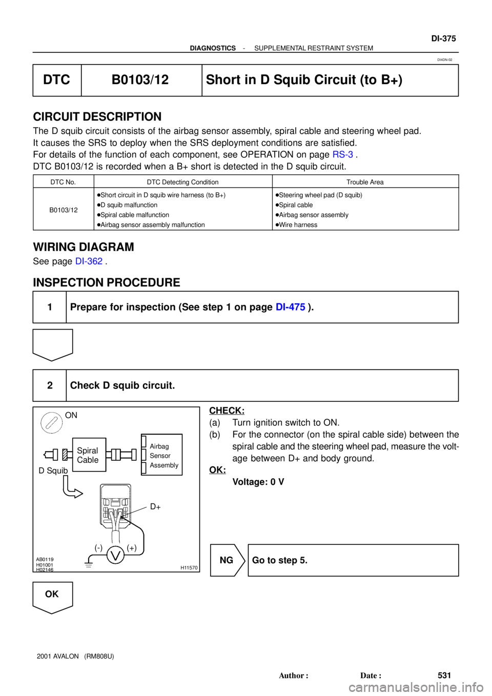
2 Check D squib circuit.
CHECK:
(a) Turn ignition switch to ON.
(b) For the connector (on the spiral cable side) between the
spiral cable and the steering wheel pad, measure the volt-
age between D+ and body ground.
OK:
Voltage: 0 V
NG Go to step 5.
OK
DI4DN-02
Page 1115 of 1897
H01454
P Squib
10Airbag Sensor Assembly
2Y-R
C6
Y-G 1
11P+
P-
C6
- DIAGNOSTICSSUPPLEMENTAL RESTRAINT SYSTEM
DI-379
535 Author�: Date�:
2001 AVALON (RM808U)
DTC B0105/53 Short in P Squib Circuit
CIRCUIT DESCRIPTION
The P squib circuit consists of the airbag sensor assembly and front passenger airbag assembly.
It causes the SRS to deploy when the SRS deployment conditions are satisfied.
For details of the function of each component, see OPERATION on page RS-3.
DTC B0105/53 is recorded when a short is detected in the P squib circuit.
DTC No.DTC Detecting ConditionTrouble Area
B0105/53
�Short circuit in P squib wire harness
�P squib malfunction
�Airbag sensor assembly malfunction�Front passenger airbag assembly (P squib)
�Airbag sensor assembly
�Wire harness
WIRING DIAGRAM
DI4CO-03
Page 1119 of 1897
R14286H02142H02251
P Squib
Airbag
Sensor
Assembly
P +
P-
(-)(+)
- DIAGNOSTICSSUPPLEMENTAL RESTRAINT SYSTEM
DI-383
539 Author�: Date�:
2001 AVALON (RM808U)
DTC B0106/54 Open in P Squib Circuit
CIRCUIT DESCRIPTION
The P squib circuit consists of the airbag sensor assembly and front passenger airbag assembly.
It causes the SRS to deploy when the SRS deployment conditions are satisfied.
For details of the function of each component, see OPERATION on page RS-3.
DTC B0106/54 is recorded when an open is detected in the P squib circuit.
DTC No.DTC Detecting ConditionTrouble Area
B0106/54
�Open circuit in P+ wire harness or P- wire harness of
squib
�P squib malfunction
�Airbag sensor assembly malfunction�Front passenger airbag assembly (P squib)
�Airbag sensor assembly
�Wire harness
WIRING DIAGRAM
See page DI-379.
INSPECTION PROCEDURE
1 Prepare for inspection (See step 1 on page DI-475).
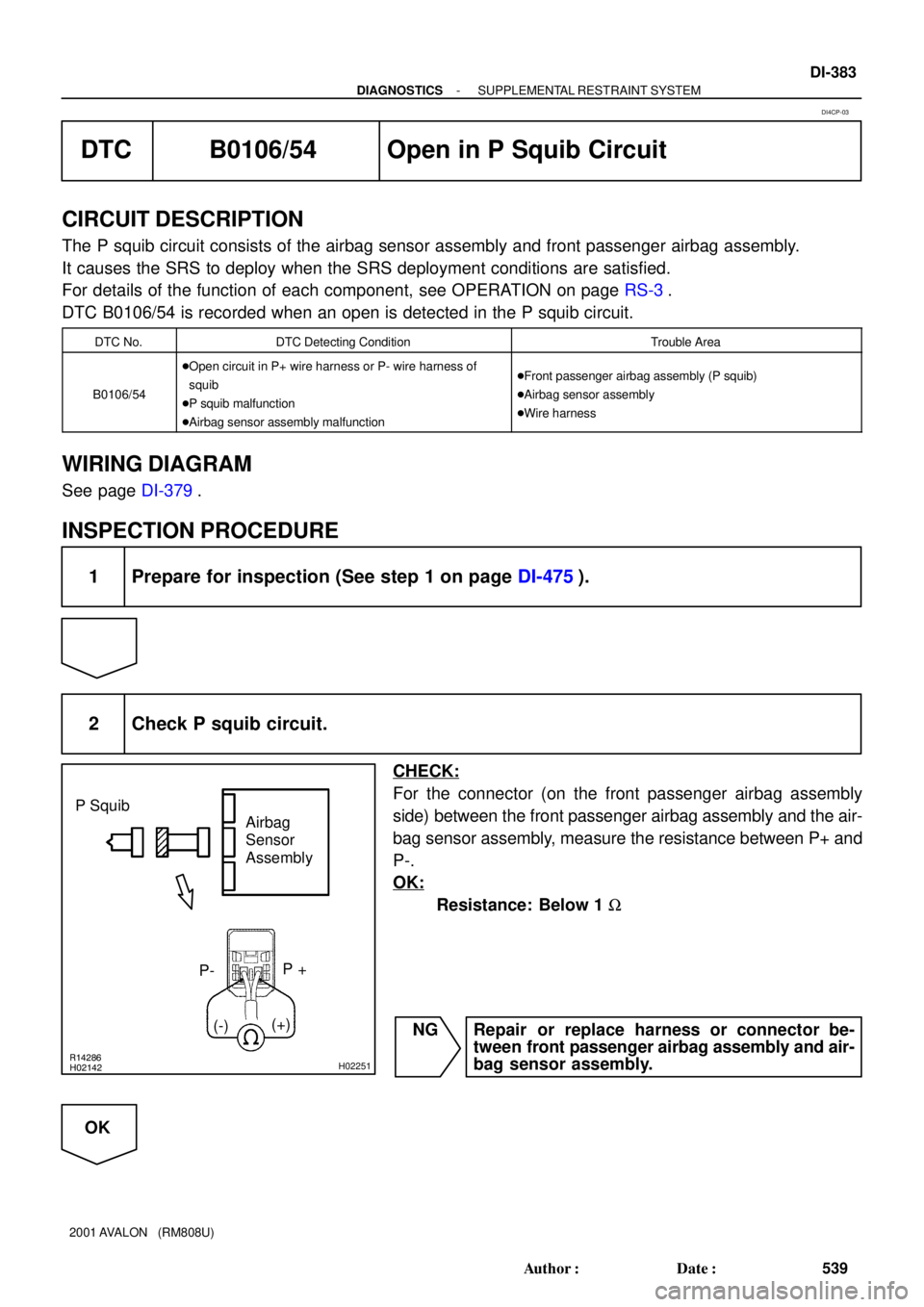
2 Check P squib circuit.
CHECK:
For the connector (on the front passenger airbag assembly
side) between the front passenger airbag assembly and the air-
bag sensor assembly, measure the resistance between P+ and
P-.
OK:
Resistance: Below 1 W
NG Repair or replace harness or connector be-
tween front passenger airbag assembly and air-
bag sensor assembly.
OK
DI4CP-03
Page 1122 of 1897
H01227H02145H02254
P Squib
Airbag
Sensor
Assembly
(+)
(-)P+
DI-386
- DIAGNOSTICSSUPPLEMENTAL RESTRAINT SYSTEM
542 Author�: Date�:
2001 AVALON (RM808U)
DTC B0107/51 Short in P Squib Circuit (to Ground)
CIRCUIT DESCRIPTION
The P squib circuit consists of the airbag sensor assembly and front passenger airbag assembly.
It causes the SRS to deploy when the SRS deployment conditions are satisfied.
For details of the function of each component, see OPERATION on page RS-3.
DTC B0107/51 is recorded when ground short is detected in the P squib circuit.
DTC No.DTC Detecting ConditionTrouble Area
B0107/51
�Short circuit in P squib wire harness (to ground)
�P squib malfunction
�Airbag sensor assembly malfunction�Front passenger airbag assembly (P squib)
�Airbag sensor assembly
�Wire harness
WIRING DIAGRAM
See page DI-379.
INSPECTION PROCEDURE
1 Prepare for inspection (See step 1 on page DI-475).
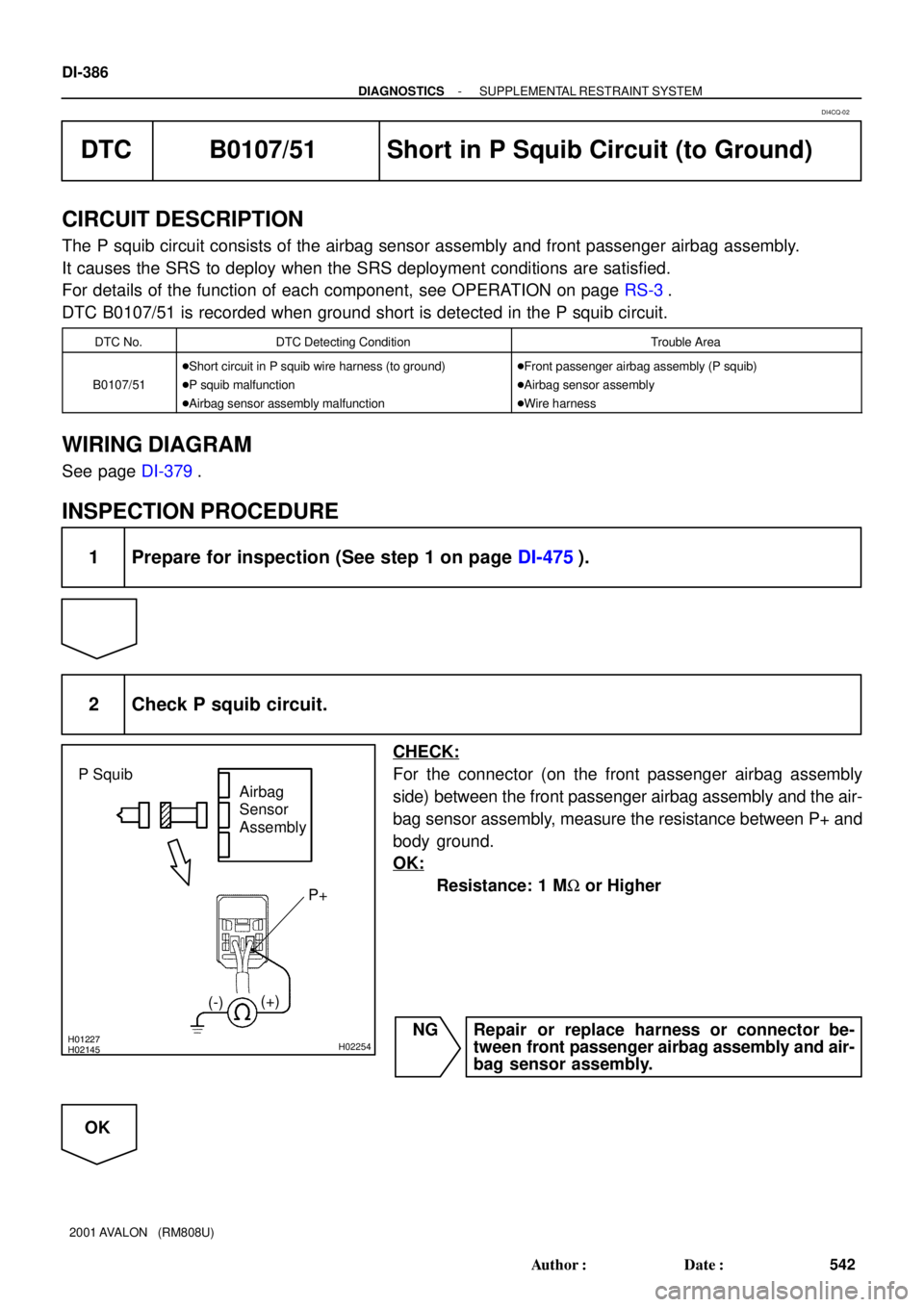
2 Check P squib circuit.
CHECK:
For the connector (on the front passenger airbag assembly
side) between the front passenger airbag assembly and the air-
bag sensor assembly, measure the resistance between P+ and
body ground.
OK:
Resistance: 1 MW or Higher
NG Repair or replace harness or connector be-
tween front passenger airbag assembly and air-
bag sensor assembly.
OK
DI4CQ-02