Page 617 of 1897

DI-230- DIAGNOSTICSANTI-LOCK BRAKE SYSTEM WITH ELECTRONIC
BRAKE FORCE DISTRIBUTION (EBD)
386 Author�: Date�:
2001 AVALON (RM808U)
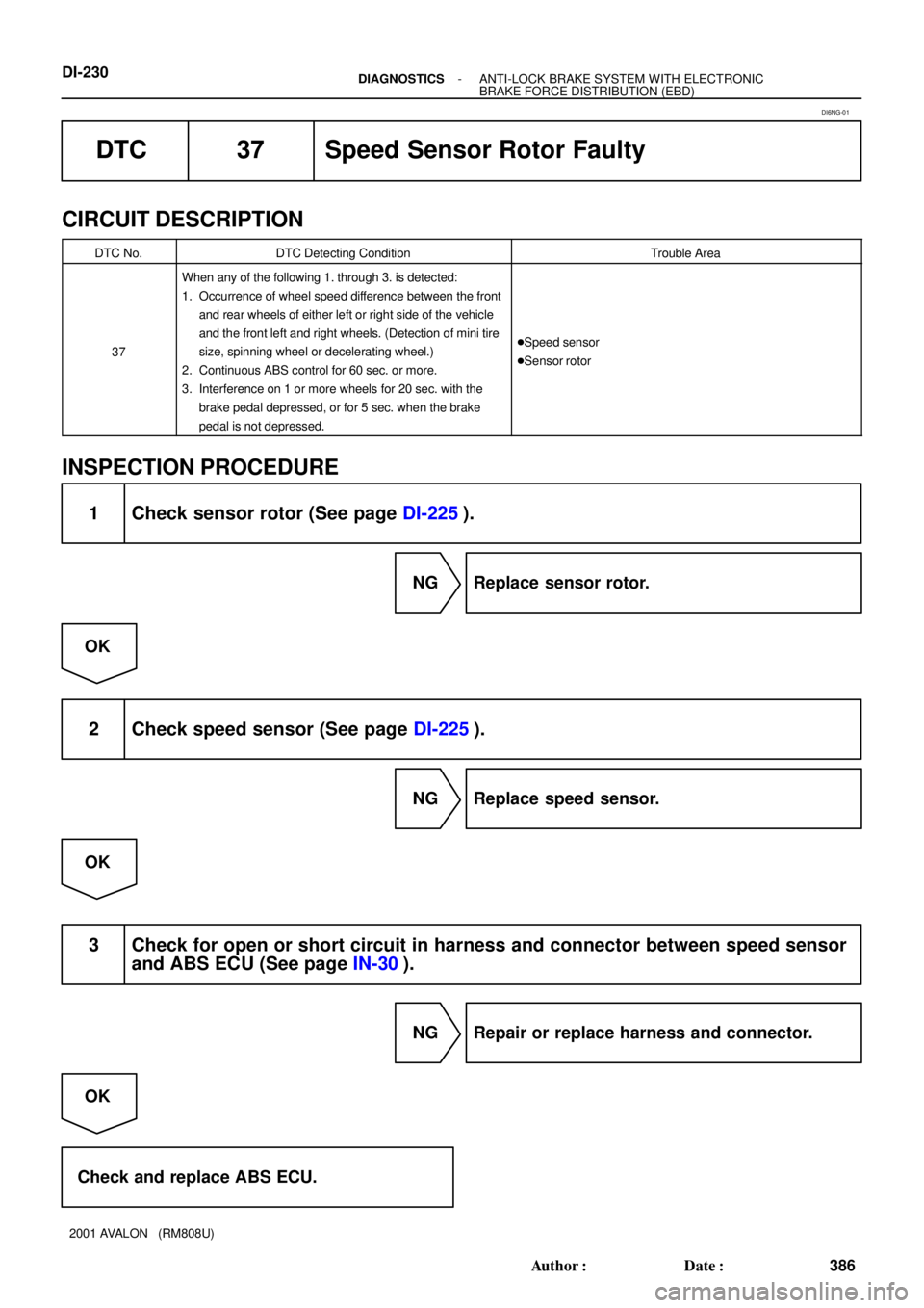
DTC 37 Speed Sensor Rotor Faulty
CIRCUIT DESCRIPTION
DTC No.DTC Detecting ConditionTrouble Area
37
When any of the following 1. through 3. is detected:
1. Occurrence of wheel speed difference between the front
and rear wheels of either left or right side of the vehicle
and the front left and right wheels. (Detection of mini tire
size, spinning wheel or decelerating wheel.)
2. Continuous ABS control for 60 sec. or more.
3. Interference on 1 or more wheels for 20 sec. with the
brake pedal depressed, or for 5 sec. when the brake
pedal is not depressed.
�Speed sensor
�Sensor rotor
INSPECTION PROCEDURE
1 Check sensor rotor (See page DI-225).
NG Replace sensor rotor.
OK
2 Check speed sensor (See page DI-225).
NG Replace speed sensor.
OK
3 Check for open or short circuit in harness and connector between speed sensor
and ABS ECU (See page IN-30).
NG Repair or replace harness and connector.
OK
Check and replace ABS ECU.
DI6NG-01
Page 623 of 1897
DI-236- DIAGNOSTICSANTI-LOCK BRAKE SYSTEM WITH ELECTRONIC
BRAKE FORCE DISTRIBUTION (EBD)
392 Author�: Date�:
2001 AVALON (RM808U)
DTC 62 ABS ECU Malfunction
CIRCUIT DESCRIPTION
DTC No.DTC Detecting ConditionTrouble Area
62ABS ECU continuously detects the proper operation of
ABS.ABS ECU
INSPECTION PROCEDURE
1 Is DTC output?
Check the DTC on page DI-212.
YES Repair circuit indicated by the code output.
NO
2 Is normal code displayed?
YES Check for short circuit in harness and connec-
tor between DLC1 or DLC2 and ABS ECU (See
page IN-30).
NO
3 Is ABS warning light off?
YES Check open and short circuit of the harness and
connector in the Tc circuit between ABS ECU
and DLC2 or DLC1.
NO
DI6NJ-01
Page 657 of 1897
F07890
1
2 3
4 5 6
7 89 10 11 12
(+) (-)
15
- DIAGNOSTICSABS WITH EBD & BA & TRAC & VSC SYSTEM
DI-275
431 Author�: Date�:
2001 AVALON (RM808U)
INSPECTION PROCEDURE
1 Check brake actuator solenoid.
PREPARATION:
Disconnect the connector from brake actuator.
CHECK:
Check continuity between terminals 10 and each of 1, 2, 3, 4,
5, 6, 7, 8, 9, 11, 12, 15 of brake actuator connector.
OK:
Continuity
NG Replace brake actuator.
OK
2 Check for open and short circuit in harness and connector between ABS & BA &
TRAC & VSC ECU and brake actuator (See page IN-30).
NG Repair or replace harness or connector.
OK
If the same code is still output after the DTC is deleted, check the contact condition of each con-
nection. If the connections are normal, the ECU may be defective.
Page 661 of 1897

F07900
Engine Room R/B No. 8 ABS Motor Relay
2
ECUBrake Actuator
13 27
- DIAGNOSTICSABS WITH EBD & BA & TRAC & VSC SYSTEM
DI-279
435 Author�: Date�:
2001 AVALON (RM808U)
5 Check continuity between terminal BM (2) of engine room R/B No. 8 (for ABS mo-
tor relay) and terminal MT (27) of ABS & BA & TRAC & VSC ECU.
PREPARATION:
Disconnect the connector from the ABS & BA & TRAC & VSC
ECU.
CHECK:
(a) Check continuity between terminal BM (2) of engine room
R/B No. 8 and terminal GND (28) of ABS & BA & TRAC
& VSC ECU.
(b) Check continuity between terminal BM (2) of engine room
R/B No. 8 and terminal MT (27) of ABS & BA & TRAC &
VSC ECU.
OK:
Continuity
NG Repair or replace harness or brake actuator.
OK
6 Check for open and short circuit in harness and connector between ABS motor
relay and ABS & BA & TRAC &VSC ECU (See page IN-30).
NG Repair or replace harness or connector.
OK
If the same code is still output after the DTC is deleted, check the contact condition of each con-
nection. If the connections are normal, the ECU may be defective.
Page 666 of 1897

F07892
ECU ABS
Solenoid
Relay
Brake
Actuator3 Engine Room R/B No. 8
5 25
49 52
6 2650 533 4
54
55
DI-284
- DIAGNOSTICSABS WITH EBD & BA & TRAC & VSC SYSTEM
440 Author�: Date�:
2001 AVALON (RM808U)
3 Check continuity between terminal 3 of engine room R/B No. 8 (for ABS solenoid
relay) and each solenoid terminal of ABS & BA & TRAC & VSC ECU.
PREPARATION:
Disconnect the connector from the ABS & BA & TRAC & VSC
ECU.
CHECK:
Check continuity between terminal 3 of engine room R/B No. 8
and each terminal, 3, 4, 5, 6, 25, 26, 49, 50, 52, 53, 54 and 55
of ECU harness side connector.
OK:
Continuity
HINT:
Resistance of each solenoid coil.
SFLH (5), SRRH (6), SFRH (26), SMC1 (49), SMC2 (50), SRLH
(53): 8 - 9.1 W
SFLR (3), SRRR (4), SRLR (25), SRC2 (52), SRC1 (54), SFRR
(55): 4.0 - 4.6 W
NG Repair or replace harness or brake actuator.
OK
4 Check for open and short circuit in harness and connector between ABS sole-
noid relay and ABS & BA & TRAC & VSC ECU (See page IN-30).
NG Repair or replace harness or connector.
OK
If the same code is still output after the DTC is deleted, check the contact condition of each con-
nection. If the connections are normal, the ECU may be defective.
Page 675 of 1897

- DIAGNOSTICSABS WITH EBD & BA & TRAC & VSC SYSTEM
DI-294
449 Author�: Date�:
INSPECTION PROCEDURE
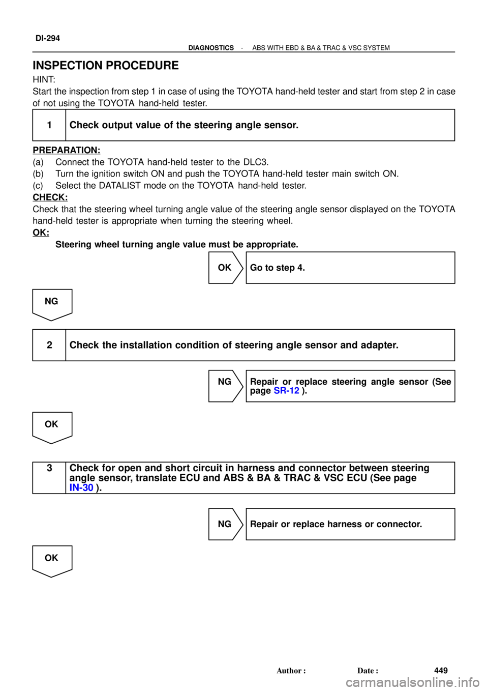
HINT:
Start the inspection from step 1 in case of using the TOYOTA hand-held tester and start from step 2 in case
of not using the TOYOTA hand-held tester.
1 Check output value of the steering angle sensor.
PREPARATION:
(a) Connect the TOYOTA hand-held tester to the DLC3.
(b) Turn the ignition switch ON and push the TOYOTA hand-held tester main switch ON.
(c) Select the DATALIST mode on the TOYOTA hand-held tester.
CHECK:
Check that the steering wheel turning angle value of the steering angle sensor displayed on the TOYOTA
hand-held tester is appropriate when turning the steering wheel.
OK:
Steering wheel turning angle value must be appropriate.
OK Go to step 4.
NG
2 Check the installation condition of steering angle sensor and adapter.
NG Repair or replace steering angle sensor (See
page SR-12).
OK
3 Check for open and short circuit in harness and connector between steering
angle sensor, translate ECU and ABS & BA & TRAC & VSC ECU (See page
IN-30).
NG Repair or replace harness or connector.
OK
Page 687 of 1897
- DIAGNOSTICSABS WITH EBD & BA & TRAC & VSC SYSTEM
DI-305
461 Author�: Date�:
2001 AVALON (RM808U)
DTCC1300 / 62ABS & BA & TRAC & VSC ECU Malfunction
CIRCUIT DESCRIPTION
DTC No.DTC Detecting ConditionTrouble Area
C1300 / 62ABS & BA & TRAC & VSC ECU internal malfunction is
detected.�ABS & BA & TRAC & VSC ECU
INSPECTION PROCEDURE
1 Check the DTC for the ABS and VSC (See page DI-252).
*1 Repair ABS and VSC control system according
to the code output.
*2
Check if ECU is connected to malfunction in-
dicator light.
*1: Output NG code
*2: Malfunction indicator light remains ON
DI6O9-01
Page 696 of 1897
F09477
ON
NEO
13
F03007
(Reference)
3 - 6 V
Below 1 V
DI-314
- DIAGNOSTICSABS WITH EBD & BA & TRAC & VSC SYSTEM
470 Author�: Date�:
2001 AVALON (RM808U)
INSPECTION PROCEDURE
1 Check for open and short circuit in harness and connector between terminal
NEO of translate ECU and terminal NEO of ECM (See page IN-30).
NG Repair or replace harness and connector.
OK
2 Check voltage between terminal NEO (13) of translate ECU and body ground.
PREPARATION:
Remove the translate ECU with connectors still connected.
CHECK:
(a) Turn the ignition switch ON.
(b) Measure the voltage between terminal 13 of the translate
ECU and body ground under the engine conditions below.
OK:
Engine conditionVoltage
OFF (IG ON)3 - 6 V or below 1 V
ON (Idling)3 - 6 V e below 1 V (Pulse)
NG Check and replace ECM.
OK
Check and replace transrate ECU.
If the same code is still output after the DTC is deleted, check the contact condition of each con-
nection.