2001 NISSAN X-TRAIL check engine light
[x] Cancel search: check engine lightPage 1092 of 3833
EC-742
[QR25(WITHOUT EURO-OBD)]
ELECTRICAL LOAD SIGNAL
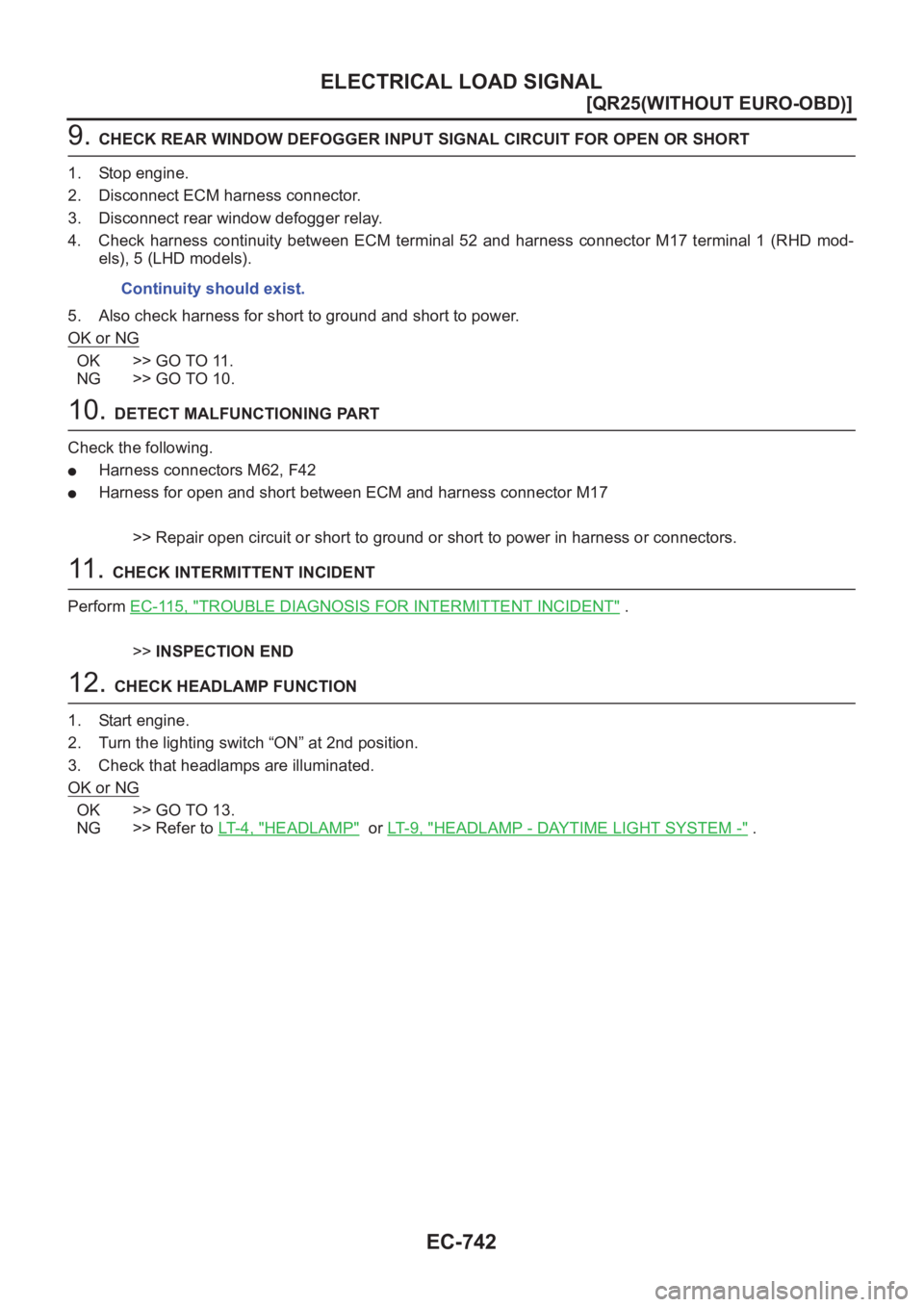
9. CHECK REAR WINDOW DEFOGGER INPUT SIGNAL CIRCUIT FOR OPEN OR SHORT
1. Stop engine.
2. Disconnect ECM harness connector.
3. Disconnect rear window defogger relay.
4. Check harness continuity between ECM terminal 52 and harness connector M17 terminal 1 (RHD mod-
els), 5 (LHD models).
5. Also check harness for short to ground and short to power.
OK or NG
OK >> GO TO 11.
NG >> GO TO 10.
10. DETECT MALFUNCTIONING PART
Check the following.
●Harness connectors M62, F42
●Harness for open and short between ECM and harness connector M17
>> Repair open circuit or short to ground or short to power in harness or connectors.
11 . CHECK INTERMITTENT INCIDENT
Perform EC-115, "
TROUBLE DIAGNOSIS FOR INTERMITTENT INCIDENT" .
>>INSPECTION END
12. CHECK HEADLAMP FUNCTION
1. Start engine.
2. Turn the lighting switch “ON” at 2nd position.
3. Check that headlamps are illuminated.
OK or NG
OK >> GO TO 13.
NG >> Refer to LT-4, "
HEADLAMP" or LT- 9 , "HEADLAMP - DAYTIME LIGHT SYSTEM -" . Continuity should exist.
Page 1093 of 3833
ELECTRICAL LOAD SIGNAL
EC-743
[QR25(WITHOUT EURO-OBD)]
C
D
E
F
G
H
I
J
K
L
MA
EC
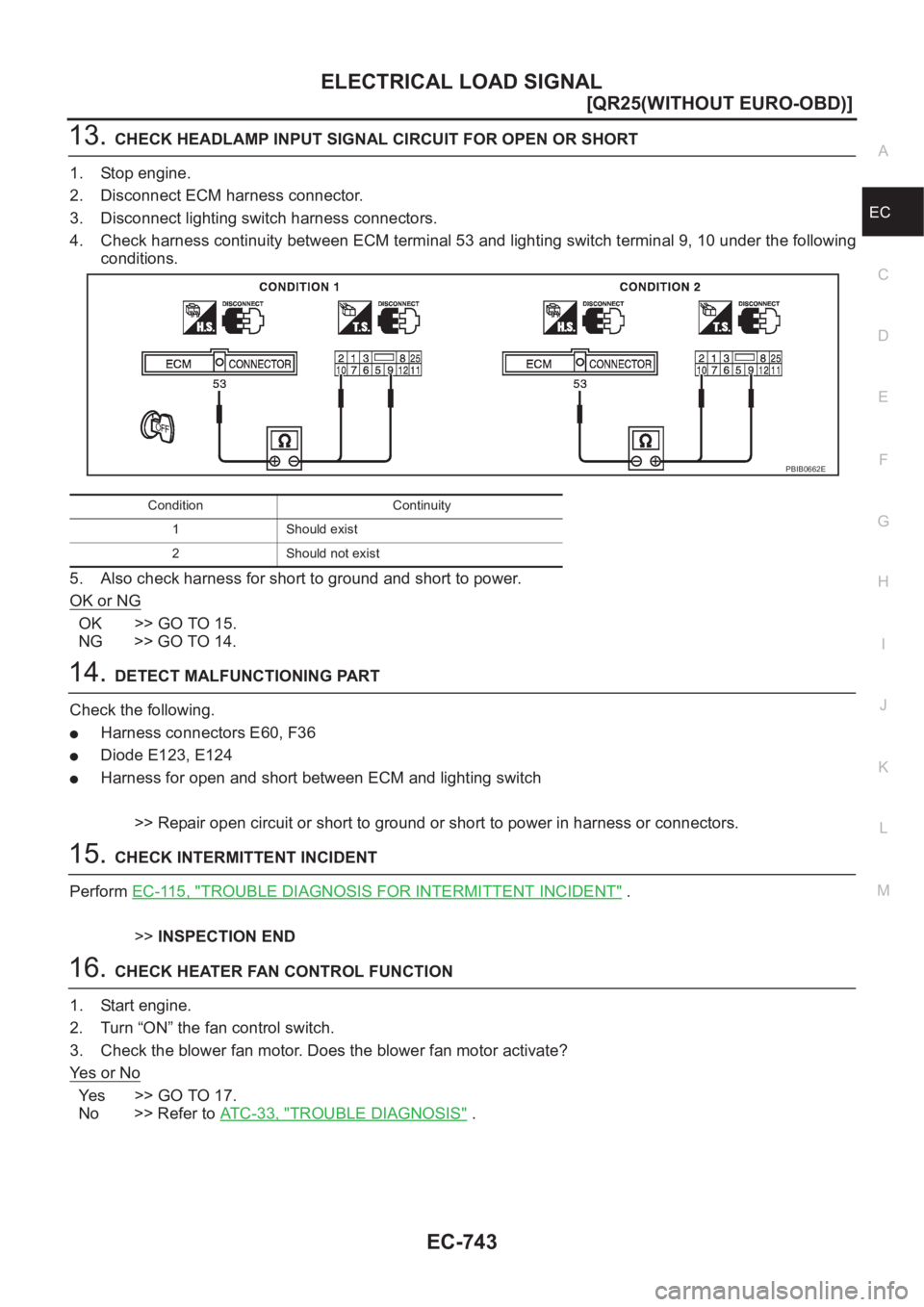
13.CHECK HEADLAMP INPUT SIGNAL CIRCUIT FOR OPEN OR SHORT
1. Stop engine.
2. Disconnect ECM harness connector.
3. Disconnect lighting switch harness connectors.
4. Check harness continuity between ECM terminal 53 and lighting switch terminal 9, 10 under the following
conditions.
5. Also check harness for short to ground and short to power.
OK or NG
OK >> GO TO 15.
NG >> GO TO 14.
14.DETECT MALFUNCTIONING PART
Check the following.
●Harness connectors E60, F36
●Diode E123, E124
●Harness for open and short between ECM and lighting switch
>> Repair open circuit or short to ground or short to power in harness or connectors.
15.CHECK INTERMITTENT INCIDENT
Perform EC-115, "
TROUBLE DIAGNOSIS FOR INTERMITTENT INCIDENT" .
>>INSPECTION END
16.CHECK HEATER FAN CONTROL FUNCTION
1. Start engine.
2. Turn “ON” the fan control switch.
3. Check the blower fan motor. Does the blower fan motor activate?
Ye s o r N o
Ye s > > G O T O 1 7 .
No >> Refer to AT C - 3 3 , "
TROUBLE DIAGNOSIS" .
Condition Continuity
1 Should exist
2 Should not exist
PBIB0662E
Page 1103 of 3833
INDEX FOR DTC
EC-753
[QR20(WITH EURO-OBD)]
C
D
E
F
G
H
I
J
K
L
MA
EC
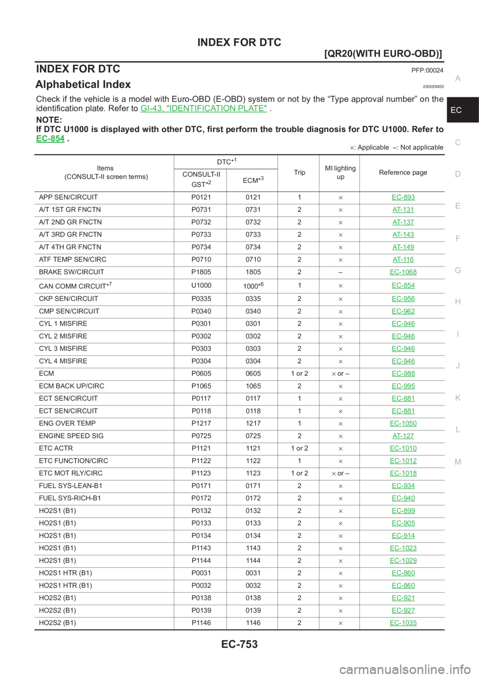
[QR20(WITH EURO-OBD)]INDEX FOR DTCPFP:00024
Alphabetical IndexEBS00MS0
Check if the vehicle is a model with Euro-OBD (E-OBD) system or not by the “Type approval number” on the
identification plate. Refer to GI-43, "
IDENTIFICATION PLATE" .
NOTE:
If DTC U1000 is displayed with other DTC, first perform the trouble diagnosis for DTC U1000. Refer to
EC-854
.
×: Applicable –: Not applicable
Items
(CONSULT-II screen terms)DTC*
1
TripMI lighting
upReference page
CONSULT-II
GST*
2ECM*3
APP SEN/CIRCUIT P0121 0121 1×EC-893
A/T 1ST GR FNCTN P0731 0731 2×AT-131
A/T 2ND GR FNCTN P0732 0732 2×AT-137
A/T 3RD GR FNCTN P0733 0733 2×AT-143
A/T 4TH GR FNCTN P0734 0734 2×AT-149
ATF TEMP SEN/CIRC P0710 0710 2×AT- 11 6
BRAKE SW/CIRCUIT P1805 1805 2 –EC-1068
CAN COMM CIRCUIT*7U1000
1000*61×EC-854
CKP SEN/CIRCUIT P0335 0335 2×EC-956
CMP SEN/CIRCUIT P0340 0340 2×EC-962
CYL 1 MISFIRE P0301 0301 2×EC-946
CYL 2 MISFIRE P0302 0302 2×EC-946
CYL 3 MISFIRE P0303 0303 2×EC-946
CYL 4 MISFIRE P0304 0304 2×EC-946
ECM P0605 0605 1 or 2× or –EC-988
ECM BACK UP/CIRC P1065 1065 2×EC-995
ECT SEN/CIRCUIT P0117 0117 1×EC-881
ECT SEN/CIRCUIT P0118 0118 1×EC-881
ENG OVER TEMP P1217 1217 1×EC-1050
ENGINE SPEED SIG P0725 0725 2×AT-127
ETC ACTR P1121 1121 1 or 2×EC-1010
ETC FUNCTION/CIRC P1122 1122 1×EC-1012
ETC MOT RLY/CIRC P1123 1123 1 or 2× or –EC-1018
FUEL SYS-LEAN-B1 P0171 0171 2×EC-934
FUEL SYS-RICH-B1 P0172 0172 2×EC-940
HO2S1 (B1) P0132 0132 2×EC-899
HO2S1 (B1) P0133 0133 2×EC-905
HO2S1 (B1) P0134 0134 2×EC-914
HO2S1 (B1) P1143 1143 2×EC-1023
HO2S1 (B1) P1144 1144 2×EC-1029
HO2S1 HTR (B1) P0031 0031 2×EC-860
HO2S1 HTR (B1) P0032 0032 2×EC-860
HO2S2 (B1) P0138 0138 2×EC-921
HO2S2 (B1) P0139 0139 2×EC-927
HO2S2 (B1) P1146 1146 2×EC-1035
Page 1123 of 3833
BASIC SERVICE PROCEDURE
EC-773
[QR20(WITH EURO-OBD)]
C
D
E
F
G
H
I
J
K
L
MA
EC
Learning will be cancelled if any of the following conditions are missed for even a moment.
●Battery voltage: More than 12.9V (At idle)
●Engine coolant temperature: 70 - 100°C (158 - 212°F)
●PNP switch: ON
●Electric load switch: OFF
(Air conditioner, headlamp, rear window defogger)
On vehicles equipped with daytime light systems, set lighting switch to the 1st position to light
only small lamps.
●Steering wheel: Neutral (Straight-ahead position)
●Vehicle speed: Stopped
●Transmission: Warmed-up
For A/T models with CONSULT-II, drive vehicle until “FLUID TEMP SE” in “DATA MONITOR” mode of “A/
T” system indicates less than 0.9V.
For A/T models without CONSULT-II and M/T models, drive vehicle for 10 minutes.
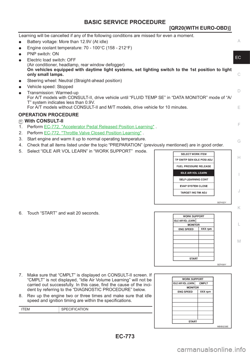
OPERATION PROCEDURE
With CONSULT-II
1. Perform EC-772, "Accelerator Pedal Released Position Learning" .
2. Perform EC-772, "
Throttle Valve Closed Position Learning" .
3. Start engine and warm it up to normal operating temperature.
4. Check that all items listed under the topic “PREPARATION” (previously mentioned) are in good order.
5. Select “IDLE AIR VOL LEARN” in “WORK SUPPORT” mode.
6. Touch “START” and wait 20 seconds.
7. Make sure that “CMPLT” is displayed on CONSULT-II screen. If
“CMPLT” is not displayed, “Idle Air Volume Learning” will not be
carried out successfully. In this case, find the cause of the inci-
dent by referring to the “DIAGNOSTIC PROCEDURE” below.
8. Rev up the engine two or three times and make sure that idle
speed and ignition timing are within the specifications.
SEF452Y
SEF454Y
ITEM SPECIFICATION
MBIB0238E
Page 1127 of 3833
ON BOARD DIAGNOSTIC (OBD) SYSTEM
EC-777
[QR20(WITH EURO-OBD)]
C
D
E
F
G
H
I
J
K
L
MA
EC
ON BOARD DIAGNOSTIC (OBD) SYSTEMPFP:00028
IntroductionEBS00MSL
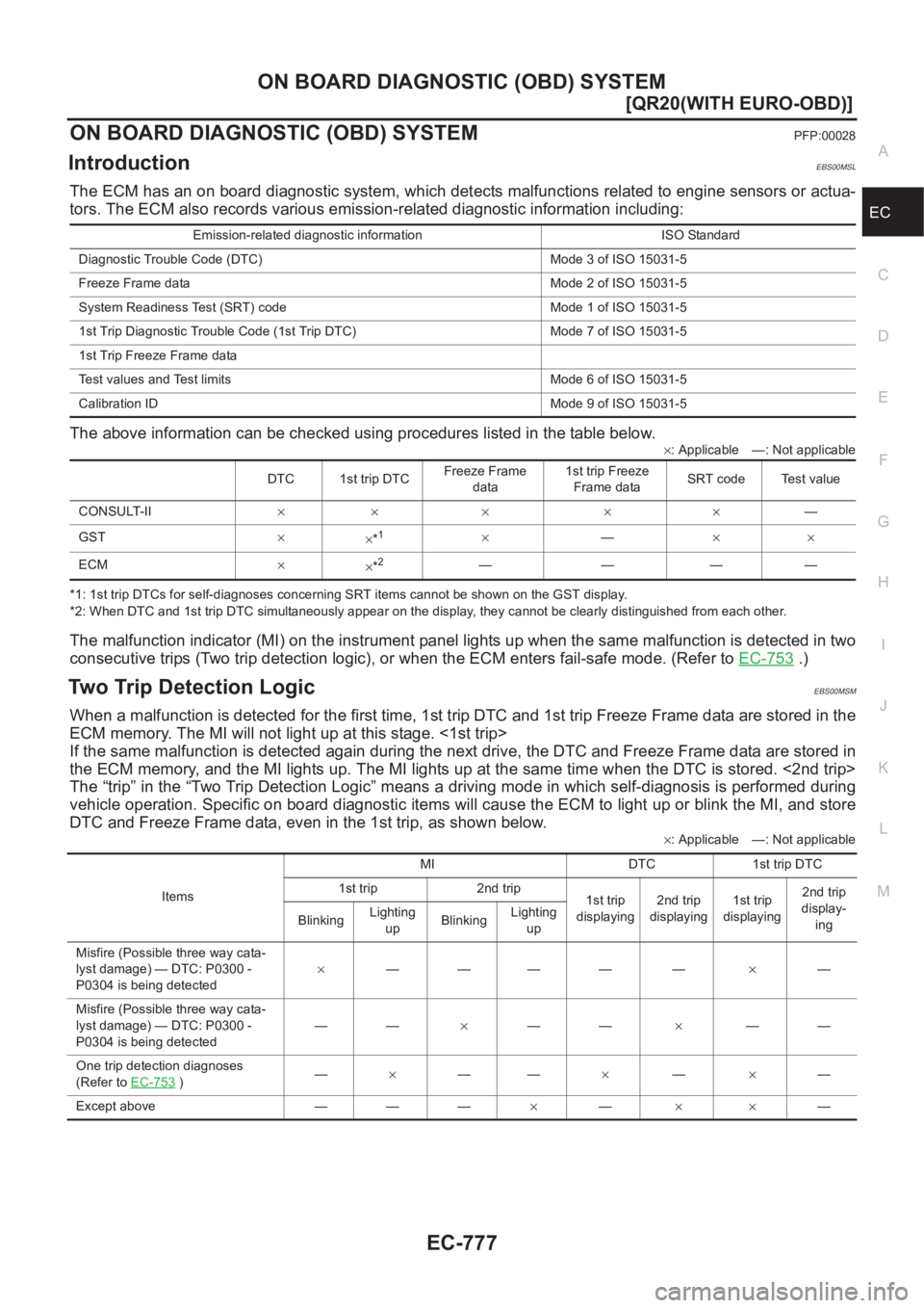
The ECM has an on board diagnostic system, which detects malfunctions related to engine sensors or actua-
tors. The ECM also records various emission-related diagnostic information including:
The above information can be checked using procedures listed in the table below.
×: Applicable —: Not applicable
*1: 1st trip DTCs for self-diagnoses concerning SRT items cannot be shown on the GST display.
*2: When DTC and 1st trip DTC simultaneously appear on the display, they cannot be clearly distinguished from each other.
The malfunction indicator (MI) on the instrument panel lights up when the same malfunction is detected in two
consecutive trips (Two trip detection logic), or when the ECM enters fail-safe mode. (Refer to EC-753
.)
Two Trip Detection LogicEBS00MSM
When a malfunction is detected for the first time, 1st trip DTC and 1st trip Freeze Frame data are stored in the
ECM memory. The MI will not light up at this stage. <1st trip>
If the same malfunction is detected again during the next drive, the DTC and Freeze Frame data are stored in
the ECM memory, and the MI lights up. The MI lights up at the same time when the DTC is stored. <2nd trip>
The “trip” in the “Two Trip Detection Logic” means a driving mode in which self-diagnosis is performed during
vehicle operation. Specific on board diagnostic items will cause the ECM to light up or blink the MI, and store
DTC and Freeze Frame data, even in the 1st trip, as shown below.
×: Applicable —: Not applicable Emission-related diagnostic information ISO Standard
Diagnostic Trouble Code (DTC) Mode 3 of ISO 15031-5
Freeze Frame data Mode 2 of ISO 15031-5
System Readiness Test (SRT) code Mode 1 of ISO 15031-5
1st Trip Diagnostic Trouble Code (1st Trip DTC) Mode 7 of ISO 15031-5
1st Trip Freeze Frame data
Test values and Test limits Mode 6 of ISO 15031-5
Calibration ID Mode 9 of ISO 15031-5
DTC 1st trip DTCFreeze Frame
data1st trip Freeze
Frame dataSRT code Test value
CONSULT-II×× × × ×—
GST×
×*
1×—××
ECM×
×*
2————
ItemsMI DTC 1st trip DTC
1st trip 2nd trip
1st trip
displaying2nd trip
displaying1st trip
displaying2nd trip
display-
ing BlinkingLighting
upBlinkingLighting
up
Misfire (Possible three way cata-
lyst damage) — DTC: P0300 -
P0304 is being detected×———— —×—
Misfire (Possible three way cata-
lyst damage) — DTC: P0300 -
P0304 is being detected——×——×——
One trip detection diagnoses
(Refer to EC-753
)—×——×—×—
Except above — — —×—××—
Page 1130 of 3833
EC-780
[QR20(WITH EURO-OBD)]
ON BOARD DIAGNOSTIC (OBD) SYSTEM
utive trips. If a 1st trip DTC is stored and a non-diagnostic operation is performed between the 1st and 2nd
trips, only the 1st trip DTC will continue to be stored. For malfunctions that blink or light up the MI during the
1st trip, the DTC and 1st trip DTC are stored in the ECM memory.
Procedures for clearing the DTC and the 1st trip DTC from the ECM memory are described in EC-788, "
HOW
TO ERASE EMISSION-RELATED DIAGNOSTIC INFORMATION" .
For malfunctions in which 1st trip DTCs are displayed, refer to EC-778
. These items are required by legal reg-
ulations to continuously monitor the system/component. In addition, the items monitored non-continuously are
also displayed on CONSULT-II.
1st trip DTC is specified in Mode 7 of ISO 15031-5. 1st trip DTC detection occurs without lighting up the MI
and therefore does not warn the driver of a an incident. However, 1st trip DTC detection will not prevent the
vehicle from being tested, for example during Inspection/Maintenance (I/M) tests.
When a 1st trip DTC is detected, check, print out or write down and erase (1st trip) DTC and Freeze Frame
data as specified in “Work Flow” procedure Step II, refer to EC-800
. Then perform “DTC Confirmation Proce-
dure” or “Overall Function Check” to try to duplicate the malfunction. If the malfunction is duplicated, the item
requires repair.
How to Read DTC and 1st Trip DTC
DTC and 1st trip DTC can be read by the following methods.
With CONSULT-II
With GST
CONSULT-II or GST (Generic Scan Tool) Examples: P0340, P0705, P0750, etc.
These DTCs are prescribed by ISO 15031-5.
(CONSULT-II also displays the malfunctioning component or system.)
No Tools
The number of blinks of the MI in the Diagnostic Test Mode II (Self-Diagnostic Results) indicates the DTC.
Example: 0102, 0340 etc.
These DTCs are controlled by NISSAN.
●1st trip DTC No. is the same as DTC No.
●Output of a DTC indicates a malfunction. However, GST or the Diagnostic Test Mode II do not indi-
cate whether the malfunction is still occurring or has occurred in the past and has returned to nor-
mal. CONSULT-II can identify malfunction status as shown below. Therefore, using CONSULT-II (if
available) is recommended.
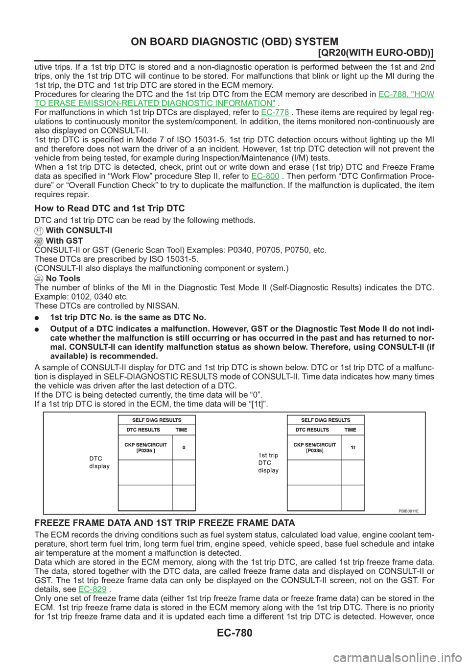
A sample of CONSULT-II display for DTC and 1st trip DTC is shown below. DTC or 1st trip DTC of a malfunc-
tion is displayed in SELF-DIAGNOSTIC RESULTS mode of CONSULT-II. Time data indicates how many times
the vehicle was driven after the last detection of a DTC.
If the DTC is being detected currently, the time data will be “0”.
If a 1st trip DTC is stored in the ECM, the time data will be “[1t]”.
FREEZE FRAME DATA AND 1ST TRIP FREEZE FRAME DATA
The ECM records the driving conditions such as fuel system status, calculated load value, engine coolant tem-
perature, short term fuel trim, long term fuel trim, engine speed, vehicle speed, base fuel schedule and intake
air temperature at the moment a malfunction is detected.
Data which are stored in the ECM memory, along with the 1st trip DTC, are called 1st trip freeze frame data.
The data, stored together with the DTC data, are called freeze frame data and displayed on CONSULT-II or
GST. The 1st trip freeze frame data can only be displayed on the CONSULT-II screen, not on the GST. For
details, see EC-829
.
Only one set of freeze frame data (either 1st trip freeze frame data or freeze frame data) can be stored in the
ECM. 1st trip freeze frame data is stored in the ECM memory along with the 1st trip DTC. There is no priority
for 1st trip freeze frame data and it is updated each time a different 1st trip DTC is detected. However, once
PBIB0911E
Page 1140 of 3833
EC-790
[QR20(WITH EURO-OBD)]
ON BOARD DIAGNOSTIC (OBD) SYSTEM
5. System readiness test (SRT) codes
6. Test values
7. Others
Actual work procedures are explained using a DTC as an example. Be careful so that not only the DTC, but all
of the data listed above, are cleared from the ECM memory during work procedures.
NATS (Nissan Anti-theft System)EBS00MSO
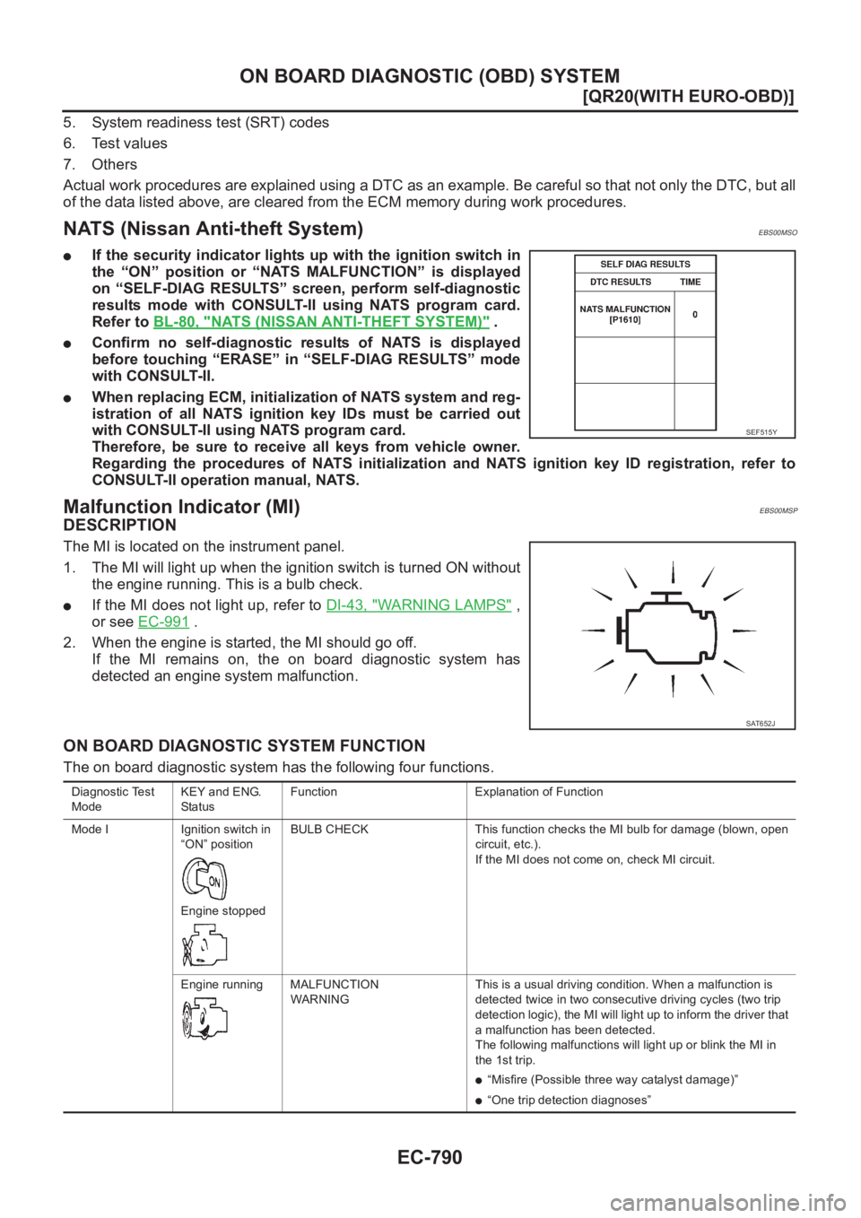
●If the security indicator lights up with the ignition switch in
the “ON” position or “NATS MALFUNCTION” is displayed
on “SELF-DIAG RESULTS” screen, perform self-diagnostic
results mode with CONSULT-II using NATS program card.
Refer to BL-80, "
NATS (NISSAN ANTI-THEFT SYSTEM)" .
●Confirm no self-diagnostic results of NATS is displayed
before touching “ERASE” in “SELF-DIAG RESULTS” mode
with CONSULT-II.
●When replacing ECM, initialization of NATS system and reg-
istration of all NATS ignition key IDs must be carried out
with CONSULT-II using NATS program card.
Therefore, be sure to receive all keys from vehicle owner.
Regarding the procedures of NATS initialization and NATS ignition key ID registration, refer to
CONSULT-II operation manual, NATS.
Malfunction Indicator (MI)EBS00MSP
DESCRIPTION
The MI is located on the instrument panel.
1. The MI will light up when the ignition switch is turned ON without
the engine running. This is a bulb check.
●If the MI does not light up, refer to DI-43, "WARNING LAMPS" ,
or see EC-991
.
2. When the engine is started, the MI should go off.
If the MI remains on, the on board diagnostic system has
detected an engine system malfunction.
ON BOARD DIAGNOSTIC SYSTEM FUNCTION
The on board diagnostic system has the following four functions.
SEF515Y
SAT652J
Diagnostic Test
ModeKEY and ENG.
Sta tusFunction Explanation of Function
Mode I Ignition switch in
“ON” position
Engine stoppedBULB CHECK This function checks the MI bulb for damage (blown, open
circuit, etc.).
If the MI does not come on, check MI circuit.
Engine running MALFUNCTION
WARNINGThis is a usual driving condition. When a malfunction is
detected twice in two consecutive driving cycles (two trip
detection logic), the MI will light up to inform the driver that
a malfunction has been detected.
The following malfunctions will light up or blink the MI in
the 1st trip.
●“Misfire (Possible three way catalyst damage)”
●“One trip detection diagnoses”
Page 1157 of 3833
TROUBLE DIAGNOSIS
EC-807
[QR20(WITH EURO-OBD)]
C
D
E
F
G
H
I
J
K
L
MA
EC
6.PERFORM IDLE AIR VOLUME LEARNING
Refer to EC-772, "
Idle Air Volume Learning" .
Is Idle Air Volume Learning carried out successfully?
Ye s o r N o
Ye s > > G O T O 7 .
No >> 1. Follow the Instruction of “Idle Air Volume Learning”.
2. GO TO 4.
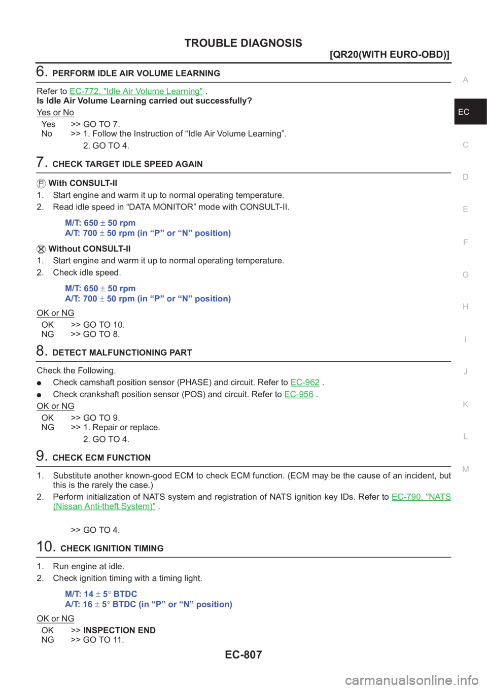
7.CHECK TARGET IDLE SPEED AGAIN
With CONSULT-II
1. Start engine and warm it up to normal operating temperature.
2. Read idle speed in “DATA MONITOR” mode with CONSULT-II.
Without CONSULT-II
1. Start engine and warm it up to normal operating temperature.
2. Check idle speed.
OK or NG
OK >> GO TO 10.
NG >> GO TO 8.
8.DETECT MALFUNCTIONING PART
Check the Following.
●Check camshaft position sensor (PHASE) and circuit. Refer to EC-962 .
●Check crankshaft position sensor (POS) and circuit. Refer to EC-956 .
OK or NG
OK >> GO TO 9.
NG >> 1. Repair or replace.
2. GO TO 4.
9.CHECK ECM FUNCTION
1. Substitute another known-good ECM to check ECM function. (ECM may be the cause of an incident, but
this is the rarely the case.)
2. Perform initialization of NATS system and registration of NATS ignition key IDs. Refer to EC-790, "
NATS
(Nissan Anti-theft System)" .
>> GO TO 4.
10.CHECK IGNITION TIMING
1. Run engine at idle.
2. Check ignition timing with a timing light.
OK or NG
OK >>INSPECTION END
NG >> GO TO 11.M/T: 650 ± 50 rpm
A/T: 700 ± 50 rpm (in “P” or “N” position)
M/T: 650 ± 50 rpm
A/T: 700 ± 50 rpm (in “P” or “N” position)
M/T: 14 ± 5° BTDC
A/T: 16 ± 5° BTDC (in “P” or “N” position)