2001 NISSAN X-TRAIL oil type
[x] Cancel search: oil typePage 1299 of 3833
![NISSAN X-TRAIL 2001 Service Repair Manual DTC P0300 - P0304 MULTIPLE CYLINDER MISFIRE, NO. 1 - 4 CYLINDER MIS-
FIRE
EC-949
[QR20(WITH EURO-OBD)]
C
D
E
F
G
H
I
J
K
L
MA
EC
5.CHECK IGNITION SPARK
1. Disconnect ignition coil assembly from rocker NISSAN X-TRAIL 2001 Service Repair Manual DTC P0300 - P0304 MULTIPLE CYLINDER MISFIRE, NO. 1 - 4 CYLINDER MIS-
FIRE
EC-949
[QR20(WITH EURO-OBD)]
C
D
E
F
G
H
I
J
K
L
MA
EC
5.CHECK IGNITION SPARK
1. Disconnect ignition coil assembly from rocker](/manual-img/5/57405/w960_57405-1298.png)
DTC P0300 - P0304 MULTIPLE CYLINDER MISFIRE, NO. 1 - 4 CYLINDER MIS-
FIRE
EC-949
[QR20(WITH EURO-OBD)]
C
D
E
F
G
H
I
J
K
L
MA
EC
5.CHECK IGNITION SPARK
1. Disconnect ignition coil assembly from rocker cover.
2. Connect a known-good spark plug to the ignition coil assembly.
3. Place end of spark plug against a suitable ground and crank engine.
4. Check for spark.
OK or NG
OK >> GO TO 6.
NG >> Check ignition coil, power transistor and their circuits.
Refer to EC-1074, "
IGNITION SIGNAL" .
6.CHECK SPARK PLUGS
Remove the spark plugs and check for fouling, etc.
OK or NG
OK >> GO TO 7.
NG >> Repair or replace spark plug(s) with standard type
one(s). For spark plug type, refer to MA-24, "
Checking
and Changing Spark Plugs" .
7.CHECK COMPRESSION PRESSURE
Check compression pressure. Refer to EM-59, "
CHECKING COMPRESSION PRESSURE" .
OK or NG
OK >> GO TO 8.
NG >> Check pistons, piston rings, valves, valve seats and cylinder head gaskets.
8.CHECK FUEL PRESSURE
1. Install all removed parts.
2. Release fuel pressure to zero. Refer to EC-775, "
FUEL PRESSURE RELEASE" .
3. Install fuel pressure gauge and check fuel pressure. Refer to EC-775, "
FUEL PRESSURE CHECK" .
OK or NG
OK >> GO TO 9.
NG >> Follow the Instruction of “FUEL PRESSURE CHECK”.
SEF575Q
SEF156I
Standard:
1,190 kPa (11.9 bar, 12.1 kg/cm2 , 172 psi)/250
rpm
Minimum:
990 kPa (9.9 bar, 10.1 kg/cm
2 , 144 psi)/250 rpm
Difference between each
cylinder:98 kPa (0.98 bar, 1.0 kg/cm
2 , 14 psi)/250 rpm
At idle: Approx. 350 kPa (3.5 bar, 3.57 kg/cm
2 , 51 psi)
Page 1472 of 3833
![NISSAN X-TRAIL 2001 Service Repair Manual EC-1122
[QR20(WITHOUT EURO-OBD)]
PRECAUTIONS
●Do not disassemble ECM.
●If a battery terminal is disconnected, the memory will return
to the ECM value.
The ECM will now start to self-control NISSAN X-TRAIL 2001 Service Repair Manual EC-1122
[QR20(WITHOUT EURO-OBD)]
PRECAUTIONS
●Do not disassemble ECM.
●If a battery terminal is disconnected, the memory will return
to the ECM value.
The ECM will now start to self-control](/manual-img/5/57405/w960_57405-1471.png)
EC-1122
[QR20(WITHOUT EURO-OBD)]
PRECAUTIONS
●Do not disassemble ECM.
●If a battery terminal is disconnected, the memory will return
to the ECM value.
The ECM will now start to self-control at its initial value.
Engine operation can vary slightly when the terminal is dis-
connected. However, this is not an indication of a malfunc-
tion. Do not replace parts because of a slight variation.
●When connecting ECM harness connector, fasten it
securely with a lever as far as it will go as shown at right.
●When connecting or disconnecting pin connectors into or
from ECM, take care not to damage pin terminals (bend or
break).
Make sure that there are not any bends or breaks on ECM
pin terminal, when connecting pin connectors.
●Securely connect ECM harness connectors.
A poor connection can cause an extremely high (surge)
voltage to develop in coil and condenser, thus resulting in
damage to ICs.
●Keep engine control system harness at least 10 cm (4 in)
away from adjacent harness, to prevent engine control sys-
tem malfunctions due to receiving external noise, degraded
operation of ICs, etc.
●Keep engine control system parts and harness dry.
●Before replacing ECM, perform “ECM Terminals and Refer-
ence Value” inspection and make sure ECM functions prop-
erly. Refer to EC-1166
.
●Handle mass air flow sensor carefully to avoid damage.
●Do not disassemble mass air flow sensor.
●Do not clean mass air flow sensor with any type of deter-
gent.
●Do not disassemble electric throttle control actuator.
●Even a slight leak in the air intake system can cause seri-
ous incidents.
●Do not shock or jar the camshaft position sensor (PHASE),
crankshaft position sensor (POS).
SEF707Y
SEF908W
PBIB0090E
MEF040D
Page 1485 of 3833
![NISSAN X-TRAIL 2001 Service Repair Manual BASIC SERVICE PROCEDURE
EC-1135
[QR20(WITHOUT EURO-OBD)]
C
D
E
F
G
H
I
J
K
L
MA
EC
BASIC SERVICE PROCEDUREPFP:00018
Idle Speed and Ignition Timing CheckEBS00N3M
IDLE SPEED
With CONSULT-II
Check idle NISSAN X-TRAIL 2001 Service Repair Manual BASIC SERVICE PROCEDURE
EC-1135
[QR20(WITHOUT EURO-OBD)]
C
D
E
F
G
H
I
J
K
L
MA
EC
BASIC SERVICE PROCEDUREPFP:00018
Idle Speed and Ignition Timing CheckEBS00N3M
IDLE SPEED
With CONSULT-II
Check idle](/manual-img/5/57405/w960_57405-1484.png)
BASIC SERVICE PROCEDURE
EC-1135
[QR20(WITHOUT EURO-OBD)]
C
D
E
F
G
H
I
J
K
L
MA
EC
BASIC SERVICE PROCEDUREPFP:00018
Idle Speed and Ignition Timing CheckEBS00N3M
IDLE SPEED
With CONSULT-II
Check idle speed in “DATA MONITOR” mode with CONSULT-II.
Without CONSULT-II
Check the idle speed by installing the pulse type tachometer clamp on the loop wire or on suitable high-tension
wire which installed between No.1 ignition coil and No.1 spark plug.
NOTE:
For the method of installing the tachometer, EC-1135, "
IGNITION TIMING" .
IGNITION TIMING
Any of following two methods may be used.
●Method A
–Attach timing light to loop wire as shown.
–Check ignition timing.
●Method B
–Remove No. 1 ignition coil.
SEF058Y
PBIB0515E
PBIB0509E
Page 1745 of 3833
![NISSAN X-TRAIL 2001 Service Repair Manual PRECAUTIONS
EC-1395
[YD]
C
D
E
F
G
H
I
J
K
L
MA
EC
PRECAUTIONSPFP:00001
Precautions for Supplemental Restraint System (SRS) “AIR BAG” and “SEAT
BELT PRE-TENSIONER”
EBS00NBT
The Supplemental NISSAN X-TRAIL 2001 Service Repair Manual PRECAUTIONS
EC-1395
[YD]
C
D
E
F
G
H
I
J
K
L
MA
EC
PRECAUTIONSPFP:00001
Precautions for Supplemental Restraint System (SRS) “AIR BAG” and “SEAT
BELT PRE-TENSIONER”
EBS00NBT
The Supplemental](/manual-img/5/57405/w960_57405-1744.png)
PRECAUTIONS
EC-1395
[YD]
C
D
E
F
G
H
I
J
K
L
MA
EC
PRECAUTIONSPFP:00001
Precautions for Supplemental Restraint System (SRS) “AIR BAG” and “SEAT
BELT PRE-TENSIONER”
EBS00NBT
The Supplemental Restraint System such as “AIR BAG” and “SEAT BELT PRE-TENSIONER”, used along
with a front seat belt, helps to reduce the risk or severity of injury to the driver and front passenger for certain
types of collision. Information necessary to service the system safely is included in the SRS and SB section of
this Service Manual.
WARNING:
●To avoid rendering the SRS inoperative, which could increase the risk of personal injury or death
in the event of a collision which would result in air bag inflation, all maintenance must be per-
formed by an authorized NISSAN/INFINITI dealer.
●Improper maintenance, including incorrect removal and installation of the SRS, can lead to per-
sonal injury caused by unintentional activation of the system. For removal of Spiral Cable and Air
Bag Module, see the SRS section.
●Do not use electrical test equipment on any circuit related to the SRS unless instructed to in this
Service Manual. SRS wiring harnesses can be identified by yellow and/or orange harness connec-
tors.
PrecautionsEBS00317
●Before connecting or disconnecting the ECM harness con-
nector, turn ignition switch OFF and disconnect negative
battery terminal. Failure to do so may damage the ECM
because battery voltage is applied to ECM even if ignition
switch is turned off.
●Do not disassemble ECM.
●When connecting or disconnecting pin connectors into or
from ECM, take care not to damage pin terminals (bend or
break).
Make sure that there are not any bends or breaks on ECM
pin terminal, when connecting pin connectors.
●Securely connect ECM harness connectors.
A poor connection can cause an extremely high (surge)
voltage to develop in coil and condenser, thus resulting in
damage to IC's.
●Keep engine control system harness at least 10cm (4 in)
away from adjacent harness, to prevent engine control sys-
tem malfunctions due to receiving external noise, degraded
operation of IC's, etc.
●Keep engine control system parts and harness dry.
SEF289H
PBIB0378E
SEF291H
Page 1749 of 3833
![NISSAN X-TRAIL 2001 Service Repair Manual ENGINE CONTROL SYSTEM
EC-1399
[YD]
C
D
E
F
G
H
I
J
K
L
MA
EC
System ChartEBS0037B
*: The input signals are sent to the ECM through CAN communication line.
Fuel Injection Control SystemEBS0036G
SYSTEM NISSAN X-TRAIL 2001 Service Repair Manual ENGINE CONTROL SYSTEM
EC-1399
[YD]
C
D
E
F
G
H
I
J
K
L
MA
EC
System ChartEBS0037B
*: The input signals are sent to the ECM through CAN communication line.
Fuel Injection Control SystemEBS0036G
SYSTEM](/manual-img/5/57405/w960_57405-1748.png)
ENGINE CONTROL SYSTEM
EC-1399
[YD]
C
D
E
F
G
H
I
J
K
L
MA
EC
System ChartEBS0037B
*: The input signals are sent to the ECM through CAN communication line.
Fuel Injection Control SystemEBS0036G
SYSTEM DESCRIPTION
Three types of fuel injection control are provided to accommodate engine operating conditions; normal control,
idle control and start control. The ECM determines the appropriate fuel injection control. Under each control,
the amount of fuel injected is adjusted to improve engine performance.
Pulse signals are exchanged between ECM and Electronic Drive Unit (EDU). EDU controls fuel injectors
according to the input signals to adjust the amount of fuel injected to the preset value.
START CONTROL
Input/Output Signal Chart
When the ECM receives a start signal from the ignition switch, the
ECM adapts the fuel injection system for the start control. The
amount of fuel injected at engine starting is a preset program value
in the ECM. The program is determined by the engine speed, engine
coolant temperature and common rail fuel pressure.
For better startability under cool engine conditions, the lower the
coolant temperature becomes, the greater the amount of fuel
injected. The ECM ends the start control when the engine speed
reaches the specific value, and shifts the control to the normal or idle
control.
Input (Sensor) ECM Function Output (Actuator)
●Accelerator pedal position sensor
●Accelerator pedal released position switch
●Common rail fuel pressure sensor
●Fuel temperature sensor
●Engine coolant temperature sensor
●Crankshaft position sensor (TDC)
●Camshaft position sensor
●Vehicle speed sensor
●ESP/TCS/ABS control unit*
●Ignition switch
●Stop L amp s witch
●Air conditioner switch
●Mass air flow sensor
●Park/neutral position switch
●Battery voltage
●Power steering oil pressure switch Fuel injection controlEDU, Fuel injectors and Suction control
valve
Fuel injection timing controlEDU, Fuel injectors and Suction control
valve
Fuel cut controlEDU, Fuel injectors and Suction control
valve
Glow control system Glow relay & glow indictor lamp
On board diagnostic system Malfunction indicator (MI)
EGR volume control EGR volume control valve
Cooling fan control Cooling fan relay
Air conditioning cut control Air conditioner relay
Sensor Input Signal to ECM ECM Function Actuator
Engine coolant temperature sensor Engine coolant temperature
Fuel injection
control (start
control)EDU
Fuel injectors
Suction control valve Crankshaft position sensor (TDC) Engine speed
Camshaft position sensor Piston position
Ignition switch Start signal
Common rail fuel pressure sensor Common rail fuel pressure
SEF648S
Page 2073 of 3833

SERVICE DATA AND SPECIFICATIONS (SDS)
MT-97
D
E
F
G
H
I
J
K
L
MA
B
MT
SERVICE DATA AND SPECIFICATIONS (SDS)PFP:00030
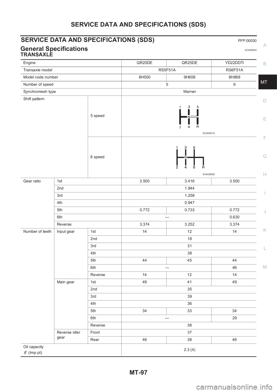
General SpecificationsECS008CE
TRANSAXLE
Engine QR20DE QR25DE YD22DDTi
Transaxle model RS5F51A RS6F51A
Model code number 8H500 9H608 8H868
Number of speed 5 6
Synchromesh typeWarner
Shift pattern
5 speed
6 speed
Gear ratio 1st 3.500 3.416 3.500
2nd 1.944
3rd 1.258
4th 0.947
5th 0.772 0.733 0.772
6th — 0.630
Reverse 3.374 3.252 3.374
Number of teeth Input gear 1st 14 12 14
2nd 18
3rd 31
4th 38
5th 444544
6th — 46
Reverse 14 12 14
Main gear 1st 49 41 49
2nd 35
3rd 39
4th 36
5th 343334
6th — 29
Reverse 38
Reverse idler
gearFront 37
Rear 46 38 46
Oil capacity
(Imp pt)2.3 (4)
SCIA0821E
SCIA0955E
Page 2705 of 3833

SERVICE DATA AND SPECIFICATIONS (SDS)
RFD-29
C
E
F
G
H
I
J
K
L
MA
B
RFD
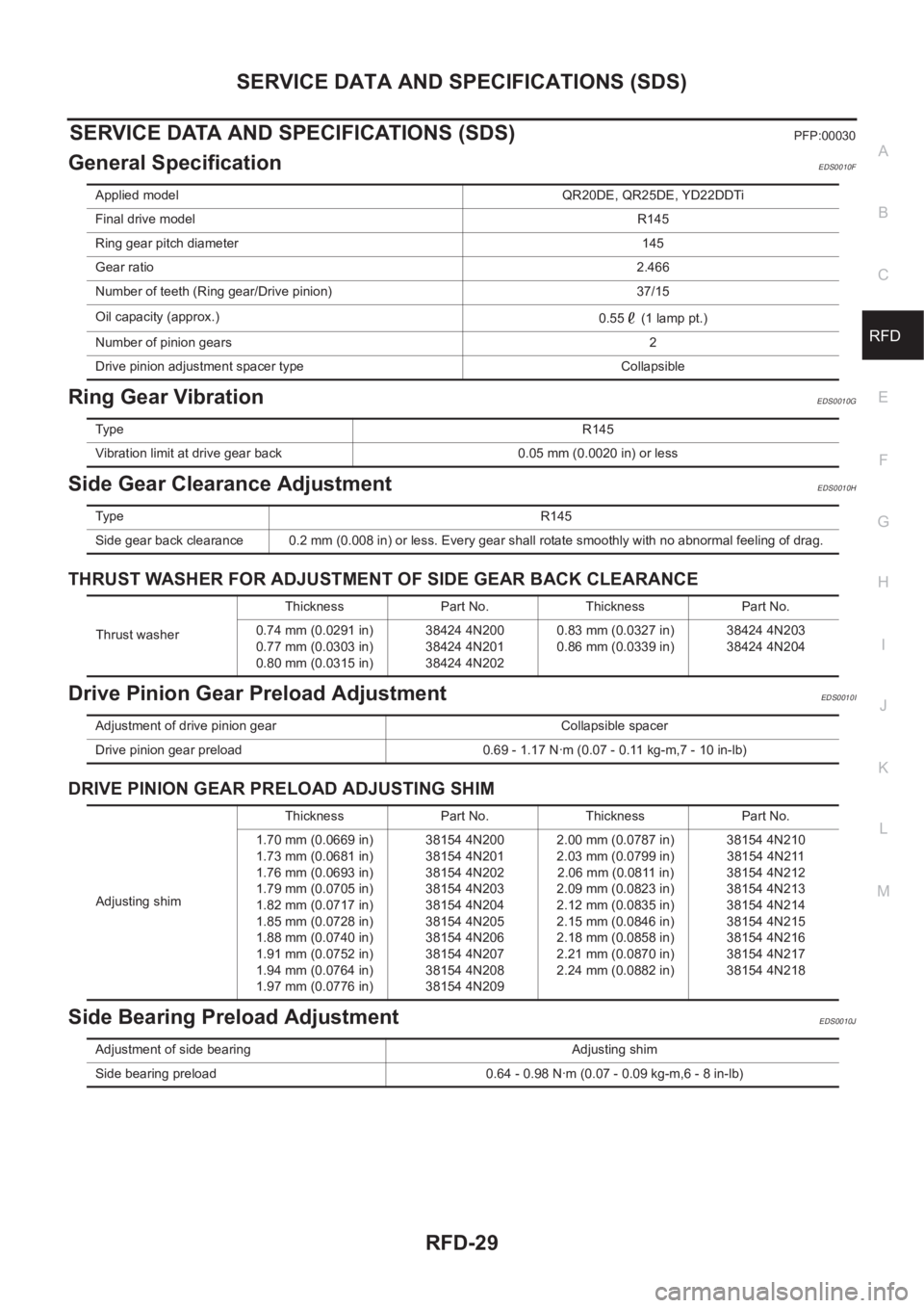
SERVICE DATA AND SPECIFICATIONS (SDS)PFP:00030
General SpecificationEDS0010F
Ring Gear VibrationEDS0010G
Side Gear Clearance AdjustmentEDS0010H
THRUST WASHER FOR ADJUSTMENT OF SIDE GEAR BACK CLEARANCE
Drive Pinion Gear Preload AdjustmentEDS0010I
DRIVE PINION GEAR PRELOAD ADJUSTING SHIM
Side Bearing Preload AdjustmentEDS0010J
Applied model QR20DE, QR25DE, YD22DDTi
Final drive modelR145
Ring gear pitch diameter 145
Gear ratio2.466
Number of teeth (Ring gear/Drive pinion) 37/15
Oil capacity (approx.)
0.55 (1 lamp pt.)
Number of pinion gears2
Drive pinion adjustment spacer type Collapsible
Ty p eR145
Vibration limit at drive gear back 0.05 mm (0.0020 in) or less
Ty p e R 1 4 5
Side gear back clearance 0.2 mm (0.008 in) or less. Every gear shall rotate smoothly with no abnormal feeling of drag.
Thrust washerThickness Part No. Thickness Part No.
0.74 mm (0.0291 in)
0.77 mm (0.0303 in)
0.80 mm (0.0315 in)38424 4N200
38424 4N201
38424 4N2020.83 mm (0.0327 in)
0.86 mm (0.0339 in)38424 4N203
38424 4N204
Adjustment of drive pinion gear Collapsible spacer
Drive pinion gear preload 0.69 - 1.17 N·m (0.07 - 0.11 kg-m,7 - 10 in-lb)
Adjusting shimThickness Part No. Thickness Part No.
1.70 mm (0.0669 in)
1.73 mm (0.0681 in)
1.76 mm (0.0693 in)
1.79 mm (0.0705 in)
1.82 mm (0.0717 in)
1.85 mm (0.0728 in)
1.88 mm (0.0740 in)
1.91 mm (0.0752 in)
1.94 mm (0.0764 in)
1.97 mm (0.0776 in)38154 4N200
38154 4N201
38154 4N202
38154 4N203
38154 4N204
38154 4N205
38154 4N206
38154 4N207
38154 4N208
38154 4N2092.00 mm (0.0787 in)
2.03 mm (0.0799 in)
2.06 mm (0.0811 in)
2.09 mm (0.0823 in)
2.12 mm (0.0835 in)
2.15 mm (0.0846 in)
2.18 mm (0.0858 in)
2.21 mm (0.0870 in)
2.24 mm (0.0882 in)38154 4N210
38154 4N211
38154 4N212
38154 4N213
38154 4N214
38154 4N215
38154 4N216
38154 4N217
38154 4N218
Adjustment of side bearing Adjusting shim
Side bearing preload 0.64 - 0.98 N·m (0.07 - 0.09 kg-m,6 - 8 in-lb)
Page 2719 of 3833

SERVICE DATA AND SPECIFICATIONS (SDS)
FSU-13
C
D
F
G
H
I
J
K
L
MA
B
FSU
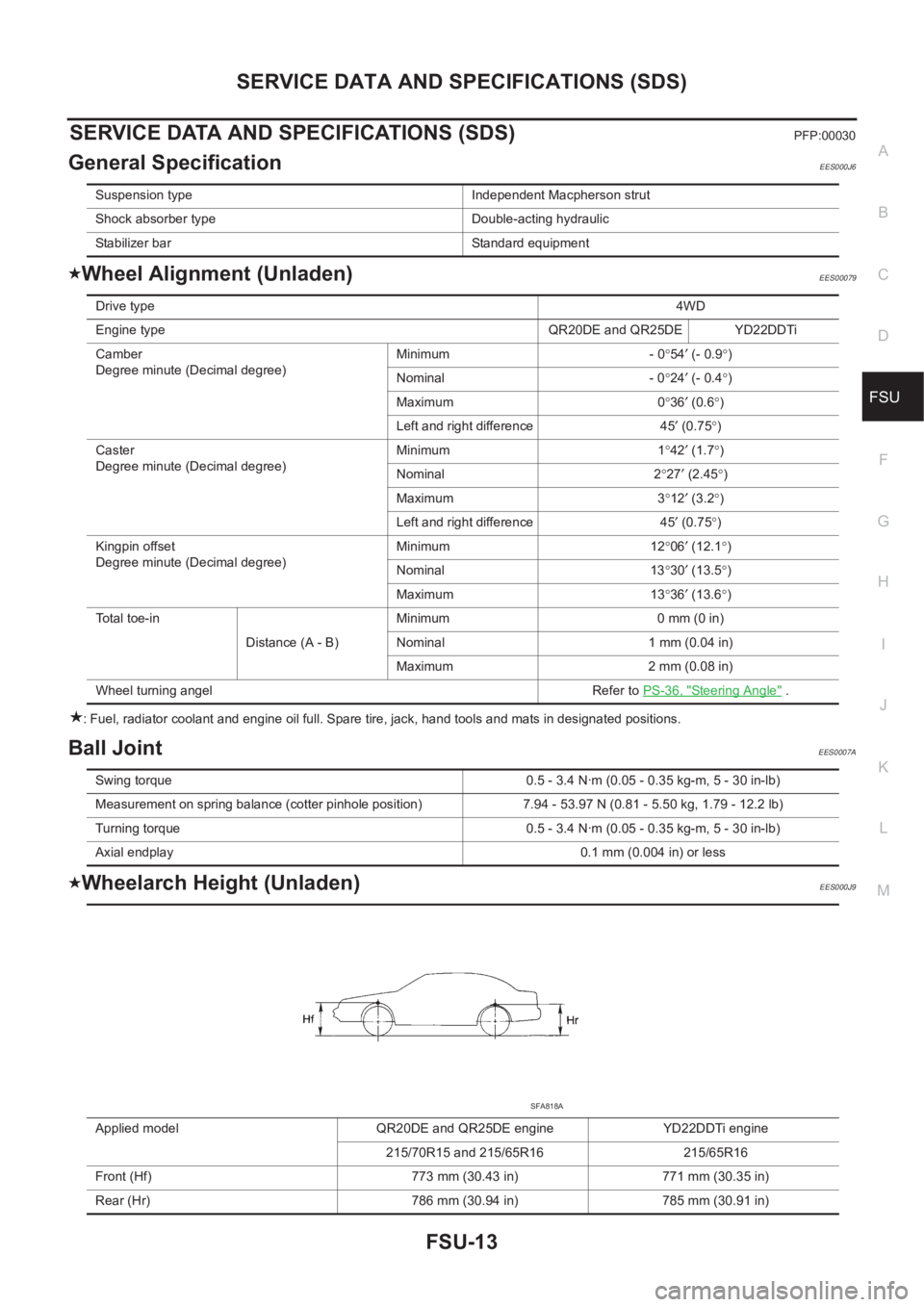
SERVICE DATA AND SPECIFICATIONS (SDS)PFP:00030
General SpecificationEES000J6
Wheel Alignment (Unladen)EES00079
: Fuel, radiator coolant and engine oil full. Spare tire, jack, hand tools and mats in designated positions.
Ball JointEES0007A
Wheelarch Height (Unladen)EES000J9
Suspension type Independent Macpherson strut
Shock absorber type Double-acting hydraulic
Stabilizer bar Standard equipment
Drive type4WD
Engine type QR20DE and QR25DE YD22DDTi
Camber
Degree minute (Decimal degree)Minimum - 0°54′ (- 0.9°)
Nominal - 0°24′ (- 0.4°)
Maximum 0°36′ (0.6°)
Left and right difference 45′ (0.75°)
Caster
Degree minute (Decimal degree)Minimum 1°42′ (1.7°)
Nominal 2°27′ (2.45°)
Maximum 3°12′ (3.2°)
Left and right difference 45′ (0.75°)
Kingpin offset
Degree minute (Decimal degree)Minimum 12°06′ (12.1°)
Nominal 13°30′ (13.5°)
Maximum 13°36′ (13.6°)
Total toe-in
Distance (A - B)Minimum 0 mm (0 in)
Nominal 1 mm (0.04 in)
Maximum 2 mm (0.08 in)
Wheel turning angel Refer to PS-36, "
Steering Angle" .
Swing torque 0.5 - 3.4 N·m (0.05 - 0.35 kg-m, 5 - 30 in-lb)
Measurement on spring balance (cotter pinhole position) 7.94 - 53.97 N (0.81 - 5.50 kg, 1.79 - 12.2 lb)
Turning torque 0.5 - 3.4 N·m (0.05 - 0.35 kg-m, 5 - 30 in-lb)
Axial endplay 0.1 mm (0.004 in) or less
Applied model QR20DE and QR25DE engine YD22DDTi engine
215/70R15 and 215/65R16 215/65R16
Front (Hf) 773 mm (30.43 in) 771 mm (30.35 in)
Rear (Hr) 786 mm (30.94 in) 785 mm (30.91 in)
SFA818A