2001 NISSAN X-TRAIL bulb
[x] Cancel search: bulbPage 2665 of 3833

TROUBLE DIAGNOSIS
TF-55
C
E
F
G
H
I
J
K
L
MA
B
TF
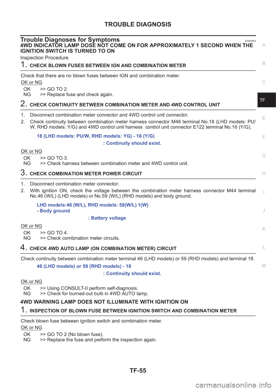
Trouble Diagnoses for SymptomsEDS000IS
4WD INDICATOR LAMP DOSE NOT COME ON FOR APPROXIMATELY 1 SECOND WHEN THE
IGNITION SWITCH IS TURNED TO ON
Inspection Procedure
1.CHECK BLOWN FUSES BETWEEN IGN AND COMBINATION METER
Check that there are no blown fuses between IGN and combination meter.
OK or NG
OK >> GO TO 2.
NG >> Replace fuse and check again.
2.CHECK CONTINUITY BETWEEN COMBINATION METER AND 4WD CONTROL UNIT
1. Disconnect combination meter connector and 4WD control unit connector.
2. Check continuity between combination meter harness connector M46 terminal No.18 (LHD models: PU/
W, RHD models: Y/G) and 4WD control unit harness control unit connector E122 terminal No.16 (Y/G).
OK or NG
OK >> GO TO 3.
NG >> Check harness between combination meter and 4WD control unit.
3.CHECK COMBINATION METER POWER CIRCUIT
1. Disconnect combination meter connector.
2. With ignition ON, check the voltage between the combination meter harness connector M44 terminal
No.46 (W/L) (LHD models) or No.59 (W/L) (RHD models) and body ground.
OK or NG
OK >> GO TO 4.
NG >> Check combination meter circuits.
4.CHECK 4WD AUTO LAMP (ON COMBINATION METER) CIRCUIT
Check continuity between combination meter terminal 46 (LHD models) or 59 (RHD models) and terminal 18.
OK or NG
OK >> Using CONSULT-II perform self-diagnosis.
NG >> Check for burned-out bulb in 4WD AUTO lamp.
4WD WARNING LAMP DOES NOT ILLUMINATE WITH IGNITION ON
1.INSPECTION OF BLOWN FUSE BETWEEN IGNITION SWITCH AND COMBINATION METER
Check blown fuse between ignition switch and combination meter.
OK or NG
OK >> GO TO 2 (No blown fuse).
NG >> Replace the fuse and perform the inspection again.18 (LHD models: PU/W, RHD models: YG) - 16 (Y/G)
: Continuity should exist.
LHD models:46 (W/L), RHD models: 59(W/L) 1(W)
- Body ground
: Battery voltage
46 (LHD models) or 59 (RHD models) - 18
: Continuity should exist.
Page 2802 of 3833
![NISSAN X-TRAIL 2001 Service Repair Manual BRC-18
[4WD/ABS]
TROUBLE DIAGNOSIS
Trouble Diagnosis Chart by Symptom
EFS001BF
When ABS and 4WD warning lamps illuminate, perform self-diagnosis.
Symptom Condition Check items Reference page
4wd indic NISSAN X-TRAIL 2001 Service Repair Manual BRC-18
[4WD/ABS]
TROUBLE DIAGNOSIS
Trouble Diagnosis Chart by Symptom
EFS001BF
When ABS and 4WD warning lamps illuminate, perform self-diagnosis.
Symptom Condition Check items Reference page
4wd indic](/manual-img/5/57405/w960_57405-2801.png)
BRC-18
[4WD/ABS]
TROUBLE DIAGNOSIS
Trouble Diagnosis Chart by Symptom
EFS001BF
When ABS and 4WD warning lamps illuminate, perform self-diagnosis.
Symptom Condition Check items Reference page
4wd indicator lamp does not come on
for approximately 1 second when the
ignition switch is turned on.IGN-ON
●Blown drive mode indicator lamp bulb
●Blown fuse between ignition and drive mode
indicator lamp
●Open circuit of wiring between ignition and
drive mode indicator lampBRC-42
ABS warning lamp does not illuminate
with ignition ON. (ABS warning lamp
check)IGN-ON
●Blown ABS warning lamp bulb
●Blown fuse between ignition and ABS warning
lamp.
●Open circuit of wiring between ignition and
ABS warning lamp.
●Malfunction in ABS systemBRC-42
ABS warning lamp illuminates with
ignition ON, but does not illuminates
after a few seconds. (ABS warning
lamp has not illuminated.)IGN-ON●4WD/ABS control unit connector discon-
nected
●Malfunction in ABS systemBRC-42
4WD warning lamp does not illuminate
with ignition ON.IGN-ON
●Blown 4WD warning lamp bulb
●Blown fuse between ignition and 4WD warn-
ing lamp
●Open circuit in wire between ignition and 4WD
warning lamp
●Open circuit in wire between 4WD warning
lamp and 4WD actuator relay
●Disconnected 4WD actuator relay
●Open circuit in wire between 4WD actuator
relay and body groundBRC-43
4WD warning lamp does not go out
several seconds after engine is started.
(Drive mode indicator lamp goes out.)Engine running●4WD/ABS control unit connector discon-
nected
●Malfunction present in 4WD systemBRC-43
Heavy tight-corner braking symptom
occurs when vehicle is driven in the fol-
lowing conditions: AUTO mode and
steering wheel is turned fully to either
sides after engine is started (Note 1,
Note 2).●Engine run-
ning
●AUTO mode
●Steering
wheel fully
turned
●Operation is not in AUTO mode (in 2WD or
LOCK mode).
●Throttle position signal error
●Mechanical malfunction of electronically con-
trolled coupling
●Malfunction present in 4WD systemBRC-44
Drive modes cannot be switched after
engine is started.Engine running
●Drive mode change-over switch is discon-
nected.
●Open circuit between drive mode change-over
switch and 4WD /ABS control unit
●Open circuit between drive mode change-over
switch and body groundBRC-45
Vehicle running, 4WD warning lamp
flashes rapidly. (When it flashes for
Approx. One minute, then does not illu-
minate.) Rapid flashing: Two times
flashing per 1 secondEngine running
(to other than
2WD mode)Protection function was activated due to heavy
load to electronically controlled coupling. (4WD
system is not malfunctioning.)BRC-45
Page 2822 of 3833
![NISSAN X-TRAIL 2001 Service Repair Manual BRC-38
[4WD/ABS]
TROUBLE DIAGNOSIS
4. HARNESS CONTINUITY INSPECTION
Drive the vehicle for a while and the perform self-diagnosis.
OK or NG
OK >> End
NG >>
●4WD/ABS control unit input/output signal i NISSAN X-TRAIL 2001 Service Repair Manual BRC-38
[4WD/ABS]
TROUBLE DIAGNOSIS
4. HARNESS CONTINUITY INSPECTION
Drive the vehicle for a while and the perform self-diagnosis.
OK or NG
OK >> End
NG >>
●4WD/ABS control unit input/output signal i](/manual-img/5/57405/w960_57405-2821.png)
BRC-38
[4WD/ABS]
TROUBLE DIAGNOSIS
4. HARNESS CONTINUITY INSPECTION
Drive the vehicle for a while and the perform self-diagnosis.
OK or NG
OK >> End
NG >>
●4WD/ABS control unit input/output signal inspection
●Recheck 4WD control unit connector terminals and connection.
Trouble Diagnoses for SymptomsEFS001CC
4WD INDICATOR LAMP DOES NOT COME ON FOR APPROXIMATELY 1 SECOND WHEN THE
IGNITION SWITCH IS TURNED TO ON
Inspection Procedure
1. CHECK BLOWN FUSES BETWEEN IGN AND COMBINATION METER
Check that there are no blown fuses between IGN and combination meter.
OK or NG
OK >> GO TO 2.
NG >> Replace fuse and check again.
2. CHECK CONTINUITY BETWEEN COMBINATION METER AND 4WD/ABS CONTROL UNIT
1. Disconnect combination meter connector and 4WD/ABS control unit connector.
2. Check continuity between combination meter harness connector M44 terminal No.18 (Y/G) and 4WD/ABS
control unit harness connector E122 terminal No.16 (Y/G).
OK or NG
OK >> GO TO 3.
NG >> Check harness between combination meter and 4WD/ABS control unit.
3. CHECK COMBINATION METER POWER CIRCUIT
1. Disconnect combination meter connector.
2. With ignition ON, check the voltage between the combination meter harness connector M46 terminal
No.46 (W/L) (LHD models) or No.59 (W/L) (RHD models) and body ground.
OK or NG
OK >> GO TO 4.
NG >> Check combination meter circuits.
4. CHECK 4WD AUTO LAMP (ON COMBINATION METER) CIRCUIT
Check continuity between combination meter terminal 46 (W/L) (LHD models) or 59 (W/L) (RHD models) and
terminal 18.
OK or NG
OK >> Using CONSULT-II perform self-diagnosis.
NG >> Check for burned-out bulb in 4WD AUTO lamp.18 (YG) - 16 (Y/G) : Continuity should exist.
46 (W/L) (LHD models) or 59 (W/L) (RHD models) - Body ground:
Battery voltage
46 (W/L) (LHD models) or 59 (RHD models) - 18:
Continuity should exist.
Page 2827 of 3833
![NISSAN X-TRAIL 2001 Service Repair Manual TROUBLE DIAGNOSIS
BRC-43
[4WD/ABS]
C
D
E
G
H
I
J
K
L
MA
B
BRC
3.CHECK CONTINUITY BETWEEN IGNITION SWITCH AND ABS WARNING LAMP
●Disconnect 4WD/ABS control unit connector.
●Check continuity between NISSAN X-TRAIL 2001 Service Repair Manual TROUBLE DIAGNOSIS
BRC-43
[4WD/ABS]
C
D
E
G
H
I
J
K
L
MA
B
BRC
3.CHECK CONTINUITY BETWEEN IGNITION SWITCH AND ABS WARNING LAMP
●Disconnect 4WD/ABS control unit connector.
●Check continuity between](/manual-img/5/57405/w960_57405-2826.png)
TROUBLE DIAGNOSIS
BRC-43
[4WD/ABS]
C
D
E
G
H
I
J
K
L
MA
B
BRC
3.CHECK CONTINUITY BETWEEN IGNITION SWITCH AND ABS WARNING LAMP
●Disconnect 4WD/ABS control unit connector.
●Check continuity between ignition switch and 4WD/ABS control module terminal No. 4. (Open circuit
check)
Is inspection result OK?
YES >> Continuity exists. Connect 4WD/ABS control module connector, check again.
NO >> Continuity does not exist. Check ABS warning lamp path.
4.CHECK FUSE
●Check if Fuse No.8 is working normally.
Is the check result OK?
YES >> Repair or replace the harness in between 4WD/ABS control unit and IGN.
NO >> Replace the fuse and replace again.
●If the figure of the monitor is with in ± 10% of the set value of E-TS solenoid electric current, 4WD/ABS C/
U is operating normally. Check for electric control coupling ASSY is required.
4WD Warning Lamp Does Not Illuminate With Ignition ON.EFS001BR
1.INSPECTION OF BLOWN 4WD WARNING LAMP BULB
●Remove glove box on the passenger side and disconnect the 4WD/ABS control unit connector.
●Confirm continuity between 4WD/ABS control unit connector terminals No. 3 (IGN) and No. 4 (ABS warn-
ing lamp).
Is inspection result OK?
YES >> GO TO 3. (Continuity exists.)
NO >>
●Check 4WD warning lamp harness.
●Remove meter control module assembly and check for blown 4WD warning lamp bulb.
2.4WD ACTUATOR RELAY HARNESS INSPECTION
●Open the hood and check that the 4WD relay is properly installed in the relay box.
●Confirm continuity between 4WD/ABS control unit connector terminals No. 7 (4WD warning lamp) and No.
104 (ground).
●Confirm continuity between 4WD/ABS control unit connector terminals No. 3 (IGN) and No. 18 (4WD
actuator relay).
Is inspection result OK?
YES >> Continuity exists. Connect 4WD/ABS control unit connector, check again.
NO >> Check ABS warning lamp harness.
4WD Warning Lamp Does Not Go Out Several Seconds After Engine Is Started.
(Drive Mode Indicator Lamp Goes Out.)
EFS001BS
1.USING CONSULT, PERFORM SELF-DIAGNOSIS
4WD warning lamp does not go out several seconds after the engine is started. (Drive mode indicator lamp
goes out.)
Is inspection result OK?
YES >> No malfunction detected. Perform inspection again.
NO >>
●Determine the location of the malfunction according to the result of self-diagnosis using CON-
SULT. (Malfunction is present in the 4WD system.)
●CONSULT-II does not display ABS -related trouble codes. Proceed to 2.
Page 2902 of 3833
![NISSAN X-TRAIL 2001 Service Repair Manual BRC-118
[ESP/TCS/ABS]
TROUBLE DIAGNOSIS
Symptom 7: SLIP Indicator Lamp Does Not Illuminate
EFS001AY
Inspection procedure
1. SLIP INDICATOR LAMP BURNED-OUT BULB INSPECTION
Check for continuity between NISSAN X-TRAIL 2001 Service Repair Manual BRC-118
[ESP/TCS/ABS]
TROUBLE DIAGNOSIS
Symptom 7: SLIP Indicator Lamp Does Not Illuminate
EFS001AY
Inspection procedure
1. SLIP INDICATOR LAMP BURNED-OUT BULB INSPECTION
Check for continuity between](/manual-img/5/57405/w960_57405-2901.png)
BRC-118
[ESP/TCS/ABS]
TROUBLE DIAGNOSIS
Symptom 7: SLIP Indicator Lamp Does Not Illuminate
EFS001AY
Inspection procedure
1. SLIP INDICATOR LAMP BURNED-OUT BULB INSPECTION
Check for continuity between the power supply terminal of meter and terminal of ABS warning lamp.
Is inspection result OK?
YES >> GO TO 2.
NO >> Circuit malfunction in SLIP indicator lamp or combination meter
2. SLIP INDICATOR LAMP POWER CIRCUIT INSPECTION
Disconnect the meter connector. Check that the voltage between the vehicle-side harness terminal and body
ground is battery voltage (Approx. 12V).
Is inspection result OK?
YES >> GO TO 3.
NO >>
●Fuse inspection
●Inspection for harness and connectors between fuse block and meter
●Check the power supply circuit (battery and ignition switch circuit).
3. SLIP INDICATOR LAMP HARNESS INSPECTION
1. Disconnect connectors for the ESP/TCS/ABS control unit and meter vehicle-side harness.
2. Check the harness between the meter and the ESP/TCS/ABS control unit for an open/shorted circuit.
Is inspection result OK?
YES >> GO TO 4.
NO >> Repair or replace the disconnected harness.
4. SLIP INDICATOR LAMP CONNECTOR INSPECTION
Check connectors for the ESP/TCS/ABS control unit and meter vehicle-side harness.
Is inspection result OK?
YES >> Connect connectors, and perform the self-diagnosis. The vehicle harness has the intermediate
connector. Refer to the vehicle wiring diagram, always check it.
NO >> Repair or replace the disconnected connector.
Symptom 8: During ESP/TCS/ABS Control, Vehicle Behavior is Jerky.EFS001AZ
Inspection procedure
1. ENGINE SPEED SIGNAL INSPECTION
Perform “DATA MONITOR” with CONSULT-II for the ESP/TCS/ABS control unit.
Is the engine speed at idle 400 rpm or higher?
YES >> Normal
NO >> GO TO 2.
2. SELF-DIAGNOSIS RESULT CHECK 1
Perform the ESP/TCS/ABS control unit self-diagnosis.
Is the self-diagnosis results displayed?
YES >> After checking and repairing the applicable item, perform the ESP/TCS/ABS control unit self-
diagnosis again.
NO >> GO TO 3.
Page 3387 of 3833

CONTROLLER
ATC-111
C
D
E
F
G
H
I
K
L
MA
B
AT C
CONTROLLERPFP:27500
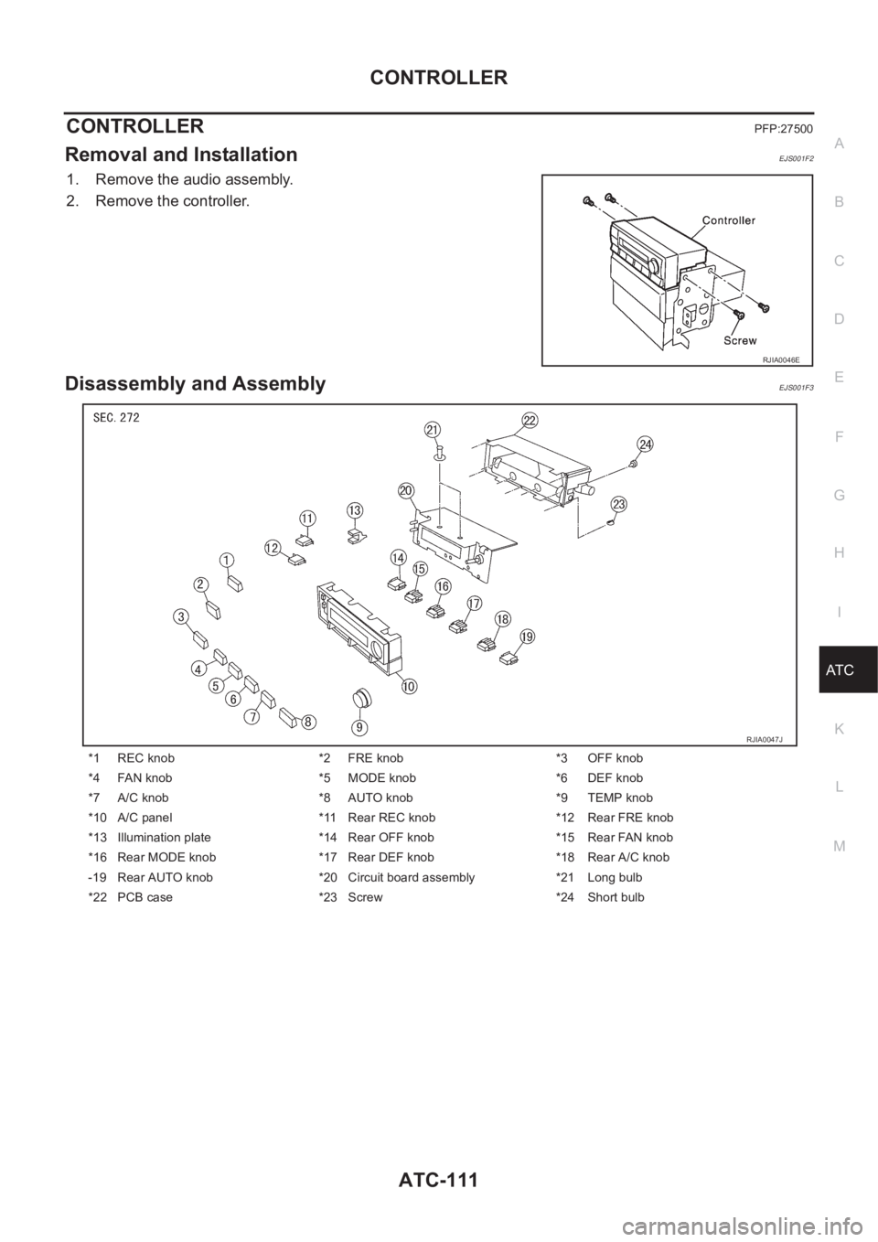
Removal and InstallationEJS001F2
1. Remove the audio assembly.
2. Remove the controller.
Disassembly and AssemblyEJS001F3
RJIA0046E
*1 REC knob *2 FRE knob *3 OFF knob
*4 FAN knob *5 MODE knob *6 DEF knob
*7 A/C knob *8 AUTO knob *9 TEMP knob
*10 A/C panel *11 Rear REC knob *12 Rear FRE knob
*13 Illumination plate *14 Rear OFF knob *15 Rear FAN knob
*16 Rear MODE knob *17 Rear DEF knob *18 Rear A/C knob
-19 Rear AUTO knob *20 Circuit board assembly *21 Long bulb
*22 PCB case *23 Screw *24 Short bulb
RJIA0047J
Page 3491 of 3833

LT-1
LIGHTING SYSTEM
K ELECTRICAL
CONTENTS
C
D
E
F
G
H
I
J
L
M
SECTION
A
B
LT
LIGHTING SYSTEM
PRECAUTION ............................................................ 3
Precautions for Supplemental Restraint System
(SRS) “AIR BAG” and “SEAT BELT PRE-TEN-
SIONER” .................................................................. 3
Precaution ................................................................ 3
Wiring Diagrams and Trouble Diagnosis .................. 3
HEADLAMP ................................................................ 4
System Description .................................................. 4
DESCRIPTION ...................................................... 4
LOW BEAM OPERATION ..................................... 4
HIGH BEAM OPERATION/FLASH-TO-PASS
OPERATION ......................................................... 4
Wiring Diagram — H/LAMP — ................................. 5
Trouble Diagnoses ................................................... 6
Aiming Adjustment ................................................... 6
LOW BEAM ........................................................... 7
Bulb Replacement .................................................... 8
HEAD LAMP ......................................................... 8
CLEARANCE LAMP ............................................. 8
Removal and Installation .......................................... 8
REMOVAL ............................................................. 8
INSTALLATION ..................................................... 8
HEADLAMP - DAYTIME LIGHT SYSTEM - ............... 9
System Description .................................................. 9
DESCRIPTION ...................................................... 9
HEADLAMP OPERATION (DAYTIME LIGHT
CANCEL OPERATION) ........................................ 9
DAYTIME LIGHT OPERATION ............................. 9
Schematic .............................................................. 10
Wiring Diagram -DTRL- ........................................... 11
Trouble Diagnoses ................................................. 14
DAYTIME LIGHT CONTROL UNIT INSPECTION
TABLE ................................................................. 14
Bulb Replacement .................................................. 14
Aiming Adjustment ................................................. 14
HEADLAMP AIMING CONTROL ............................. 15
Wiring Diagram -H/AIM- ......................................... 15
Removal and Installation ........................................ 16
Switch Circuit Inspection ........................................ 16
TURN SIGNAL AND HAZARD WARNING LAMPS ... 17System Description ................................................. 17
TURN SIGNAL OPERATION .............................. 17
HAZARD LAMP OPERATION ............................. 17
Wiring Diagram — TURN — ................................... 19
Trouble Diagnoses ................................................. 21
Electrical Components Inspection .......................... 21
COMBINATION FLASHER UNIT CHECK ........
... 21
Bulb Replacement .................................................. 22
FRONT TURN SIGNAL LAMP ............................ 22
SIDE TURN SIGNAL LAMP ................................ 22
REAR TURN SIGNAL LAMP .............................. 22
Removal and Installation for Front Turn Signal Lamp ... 22
REMOVAL ........................................................... 22
INSTALLATION ................................................... 22
Removal and Installation for Side Turn Signal Lamp ... 23
Removal and Installation for Rear Turn Signal Lamp ... 23
LIGHTING AND TURN SIGNAL SWITCH ................ 24
Removal and Installation ........................................ 24
Switch Circuit Inspection ........................................ 24
HAZARD SWITCH .................................................... 25
Removal and Installation ........................................ 25
REMOVAL ........................................................... 25
INSTALLATION ................................................... 25
STOP LAMP .............................................................. 26
Wiring Diagram — STOP/L — ................................ 26
Bulb Replacement .................................................. 27
STOP LAMP ........................................................ 27
HIGH-MOUNTED STOP LAMP ........................... 27
Removal and Installation ........................................ 27
STOP LAMP ........................................................ 27
HIGH-MOUNTED STOP LAMP ........................... 27
BACK-UP LAMP ....................................................... 28
Wiring Diagram — BACK/L — ................................ 28
Bulb Replacement .................................................. 29
Removal and Installation ........................................ 29
PARKING, LICENSE PLATE AND TAIL LAMPS ..... 30
Wiring Diagram — TAIL/L — .................................. 30
Bulb Replacement .................................................. 32
PARKING AND TAIL LAMPS .............................. 32
Page 3492 of 3833

LT-2
LICENSE PLATE LAMP ...................................... 32
Removal and Installation ........................................ 32
PARKING AND TAIL LAMPS ............................... 32
LICENSE PLATE LAMP ...................................... 32
FRONT FOG LAMP .................................................. 33
System Description ................................................. 33
DESCRIPTION .................................................... 33
FOG LAMP OPERATION .................................... 33
Wiring Diagram — F/FOG — .................................. 34
Aiming Adjustment .................................................. 35
Bulb Replacement .................................................. 36
Removal and Installation ........................................ 36
REMOVAL ........................................................... 36
INSTALLATION .................................................... 36
REAR FOG LAMP .................................................. ... 37
Wiring Diagram -R/FOG-/Without Front Fog Lamp ... 37
Wiring Diagram -R/FOG-/With Front Fog Lamp ..... 38
Bulb Replacement .................................................. 39
Removal and Installation ........................................ 39
REMOVAL ........................................................... 39
INSTALLATION .................................................... 39
CLEARANCE LAMP/TAIL LAMP ............................. 40
Bulb Replacement (Clearance Lamp) .................... 40
Bulb Replacement (Taillamp) .................................. 40
Removal and Installation of Clearance Lamp ......... 40
Removal and Installation of Taillamp ...................... 40
HIGH-MOUNTED STOP LAMP ................................ 41
Bulb Replacement .................................................. 41
Removal and Installation ........................................ 41
REAR COMBINATION LAMP ................................... 42
Wiring Diagram —STOP/L— .................................. 42
Bulb Replacement .................................................. 43
Removal and Installation ........................................ 43
REMOVAL ........................................................... 43
INSTALLATION .................................................... 43COMBINATION SWITCH .......................................... 44
Removal and Installation ......................................... 44
Switch Circuit Inspection ...................................... ... 44
ILLUMINATION .......................................................... 45
System Description ................................................. 45
Schematic ............................................................... 46
Wiring Diagram -ILL-/LHD MODELS ...................... 47
Wiring Diagram -ILL-/RHD MODELS ...................... 51
INTERIOR ROOM LAMP .......................................
... 55
System Description ................................................. 55
POWER SUPPLY AND GROUND ....................... 55
SWITCH OPERATION ......................................... 55
INTERIOR ROOM LAMP TIMER OPERATION ... 56
ON-OFF CONTROL ............................................. 56
Wiring Diagram -ROOM/L- ...................................... 57
Interior Room Lamp Timer Does Not Operate ........ 59
Interior Room Lamp Timer Does Not Cancel .......... 62
Bulb Replacement ................................................... 64
INTERIOR ROOM LAMP ..................................... 64
LUGGAGE ROOM LAMP .................................... 64
Removal and Installation ......................................... 64
INTERIOR ROOM LAMP ..................................... 64
LUGGAGE ROOM LAMP .................................... 64
SPOT LAMPS ............................................................ 65
Wiring Diagram -INT/L- ........................................... 65
Bulb Replacement ................................................... 66
SPOT LAMP (WITHOUT SUNROOF) ................. 66
SPOT LAMP (WITH SUNROOF) ......................... 66
Removal and Installation ......................................... 66
SPOT LAMP (WITHOUT SUNROOF) ................. 66
SPOT LAMP (WITH SUNROOF) ......................... 66
BULB SPECIFICATIONS .......................................... 67
Headlamp ................................................................ 67
Exterior Lamp .......................................................... 67
Interior Lamp/Illumination ........................................ 67