Page 2150 of 3833
AT-72
[EURO-OBD]
TROUBLE DIAGNOSIS — BASIC INSPECTION
3. CHECK VEHICLE MOVE
1. Turn ignition switch to “OFF” position.
2. Move selector lever to “P” position.
3. Release parking brake.
4. Push vehicle forward or backward.
5. Does vehicle move when it is pushed forward or backward?
Ye s o r N o
Yes >> Mark the box of “In “P” Position, Vehicle Moves Forward
Or Backward When Pushed” on the DIAGNOSTIC
WORKSHEET. Continue Road Test.
No >> GO TO 4
4. CHECK VEHICLE MOVE
1. Apply parking brake.
2. Move selector lever to “N” position.
3. Turn ignition switch to “START” position and start engine.
4. Release parking brake.
5. Does vehicle move forward or backward?
Ye s o r N o
Yes >> Mark the box of “In “N” Position, Vehicle Moves” on the
DIAGNOSTIC WORKSHEET. Continue Road Test.
No >> GO TO 5
SAT768B
SAT796A
SAT771B
Page 2343 of 3833
![NISSAN X-TRAIL 2001 Service Repair Manual TROUBLE DIAGNOSIS — BASIC INSPECTION
AT-265
[EXC.F/EURO-OBD]
D
E
F
G
H
I
J
K
L
MA
B
AT
Stall TestECS004VS
STALL TEST PROCEDURE
1. Check A/T fluid and engine oil levels. If necessary, add.
2. Drive](/manual-img/5/57405/w960_57405-2342.png "NISSAN X-TRAIL 2001 Service Repair Manual TROUBLE DIAGNOSIS — BASIC INSPECTION
AT-265
[EXC.F/EURO-OBD]
D
E
F
G
H
I
J
K
L
MA
B
AT
Stall TestECS004VS
STALL TEST PROCEDURE
1. Check A/T fluid and engine oil levels. If necessary, add.
2. Drive")
TROUBLE DIAGNOSIS — BASIC INSPECTION
AT-265
[EXC.F/EURO-OBD]
D
E
F
G
H
I
J
K
L
MA
B
AT
Stall TestECS004VS
STALL TEST PROCEDURE
1. Check A/T fluid and engine oil levels. If necessary, add.
2. Drive vehicle for approx. 10 minutes or until fluid and oil reach
operating temperature.
3. Set parking brake and block wheels.
4. Install a tachometer where it can be seen by driver during test.
●It is good practice to mark the point of specified engine
rpm on indicator.
5. Start engine, apply foot brake, and place selector lever in D
position.
6. Accelerate to wide open throttle gradually while applying foot
brake.
7. Quickly note the engine stall revolution and immediately release
throttle.
●During test, never hold throttle wide open for less than 5
seconds.
Stall revolution:
8. Move selector lever to “N” position.
9. Cool off ATF.
●Run engine at idle for at least one minute.
10. Repeat steps 5 through 9 with selector lever in “2”, “1” and “R”
positions.ATF operating temperature:
50 - 80°C (122 - 176°F)
SAT647B
SAT513G
SAT514G
QR20DE 2,450 - 2,950 rpm
QR25DE 2,300 - 2,750 rpm
SAT771B
Page 2346 of 3833
AT-268
[EXC.F/EURO-OBD]
TROUBLE DIAGNOSIS — BASIC INSPECTION
Line Pressure Test
ECS004VT
LINE PRESSURE TEST PORTS
Location of line pressure test ports are shown in the illustration.
●Always replace pressure plugs as they are self-sealing
bolts.
LINE PRESSURE TEST PROCEDURE
1. Check A/T fluid and engine oil levels. If necessary, add fluid or
oil.
2. Drive vehicle for approx. 10 minutes or until engine oil and AT F
reach operating temperature.
3. Install pressure gauge to corresponding line pressure port.
4. Set parking brake and block wheels.
●Continue to depress brake pedal fully while line pressure
test is being performed at stall speed.
SCIA0709E
ATF operating temperature: 50 - 80°C (122 -176°F)
SAT647B
UAT008
UAT008
Page 2351 of 3833
![NISSAN X-TRAIL 2001 Service Repair Manual TROUBLE DIAGNOSIS — BASIC INSPECTION
AT-273
[EXC.F/EURO-OBD]
D
E
F
G
H
I
J
K
L
MA
B
AT
3.CHECK VEHICLE MOVE
1. Turn ignition switch to “OFF” position.
2. Move selector lever to “P” position.](/manual-img/5/57405/w960_57405-2350.png "NISSAN X-TRAIL 2001 Service Repair Manual TROUBLE DIAGNOSIS — BASIC INSPECTION
AT-273
[EXC.F/EURO-OBD]
D
E
F
G
H
I
J
K
L
MA
B
AT
3.CHECK VEHICLE MOVE
1. Turn ignition switch to “OFF” position.
2. Move selector lever to “P” position.")
TROUBLE DIAGNOSIS — BASIC INSPECTION
AT-273
[EXC.F/EURO-OBD]
D
E
F
G
H
I
J
K
L
MA
B
AT
3.CHECK VEHICLE MOVE
1. Turn ignition switch to “OFF” position.
2. Move selector lever to “P” position.
3. Release parking brake.
4. Push vehicle forward or backward.
5. Does vehicle move when it is pushed forward or backward?
Ye s o r N o
Ye s > >●Mark the box on the DIAGNOSTIC WORKSHEET.
Refer to AT- 2 5 9 , "
DIAGNOSTIC WORKSHEET" .
●GO TO AT- 3 1 5 , "In “P” Position, Vehicle Moves For-
ward Or Backward When Pushed" .
●Continue ROAD TEST.
No >> GO TO 4.
4.CHECK VEHICLE MOVE
1. Apply parking brake.
2. Move selector lever to “N” position.
3. Turn ignition switch to “START” position and start engine.
4. Release parking brake.
5. Does vehicle move forward or backward?
Ye s o r N o
Ye s > >●Mark the box on the DIAGNOSTIC WORKSHEET.
Refer to AT- 2 5 9 , "
DIAGNOSTIC WORKSHEET" .
●GO TO AT-315, "In “N” Position, Vehicle Moves" .
●Continue ROAD TEST.
No >> GO TO 5.
SAT768B
SAT796A
SAT771B
Page 2378 of 3833
![NISSAN X-TRAIL 2001 Service Repair Manual AT-300
[EXC.F/EURO-OBD]
TROUBLE DIAGNOSIS — GENERAL DESCRIPTION
Vehicle will not run in any position.ON vehicle1. Fluid levelAT-264, "
FLUID LEVEL
CHECK"
2. Control cable adjustmentAT-416,](/manual-img/5/57405/w960_57405-2377.png "NISSAN X-TRAIL 2001 Service Repair Manual AT-300
[EXC.F/EURO-OBD]
TROUBLE DIAGNOSIS — GENERAL DESCRIPTION
Vehicle will not run in any position.ON vehicle1. Fluid levelAT-264, \"
FLUID LEVEL
CHECK\"
2. Control cable adjustmentAT-416,")
AT-300
[EXC.F/EURO-OBD]
TROUBLE DIAGNOSIS — GENERAL DESCRIPTION
Vehicle will not run in any position.ON vehicle1. Fluid levelAT-264, "
FLUID LEVEL
CHECK"
2. Control cable adjustmentAT-416, "Control Cable
Adjustment"
3. Line pressure testAT-268, "Line Pressure
Te s t"
4. Line pressure solenoid valveAT-396, "
LINE PRES-
SURE SOLENOID
VA LV E"
OFF vehicle5. Oil pumpAT-444, "
Oil Pump"
6. Torque converterAT-425, "
Locations of
Adjusting Shims, Needle
Bearings, Thrust Washers
and Snap Rings"
7. Parking componentsAT-421, "Components"
Transmission noise in “D”, “2”, “1” and
“R” positions.ON vehicle 1. Fluid levelAT-264, "
FLUID LEVEL
CHECK"
OFF vehicle 2. Torque converterAT-425, "
Locations of
Adjusting Shims, Needle
Bearings, Thrust Washers
and Snap Rings"
Failure to change from “D3 ” to “22 ”
when changing lever into “2” position.
AT- 3 4 0 , "
A/T Does Not Shift: D3→ 22
, When Selector Lever “D”→“2” Posi-
tion"
ON vehicle1. Accelerator pedal position (APP) sensorAT-362, "
ACCELE
RATOR PEDAL POSI-
TION (APP) SENSOR"
2. Shift solenoid valve BAT-372, "SHIFT SOLE-
NOID VALVE B"
3. Control valve assemblyAT-414, "
Control Valve
Assembly and Accumula-
tors"
4. Control cable adjustmentAT-416, "Control Cable
Adjustment"
OFF vehicle 5. Brake bandAT-488, "Band Servo Pis-
ton Assembly"
Gear change from “22 ” to “23 ” in “2”
position.ON vehicle1. PNP switchAT-344, "
TCM Self-diag-
nosis Does Not Activate"
2. Control cable adjustmentAT-416, "Control Cable
Adjustment"
Symptom Condition Diagnostic Item Reference Page
Page 2484 of 3833
AT-406
[ALL]
A/T SHIFT LOCK SYSTEM
A/T SHIFT LOCK SYSTEM
PFP:34950
DescriptionECS00405
●The mechanical key interlock mechanism also operates as a shift lock:
With the key switch turned to ON, the selector lever cannot be shifted from “P” (parking) to any other posi-
tion unless the brake pedal is depressed.
With the key removed, the selector lever cannot be shifted from “P” to any other position.
The key cannot be removed unless the selector lever is placed in “P”.
●The shift lock and key interlock mechanisms are controlled by the ON-OFF operation of the shift lock sole-
noid and by the operation of the rotator and slider located inside the key cylinder.
Shift Lock System Electrical Parts LocationECS00406
SCIA0781E
Page 2498 of 3833
AT-420
[ALL]
REMOVAL AND INSTALLATION
3. Tighten belts fixing transaxle.
4. Reinstall any part removed.
5. Adjust control cable. Refer to AT- 4 1 6 , "
Control Cable Adjust-
ment" .
6. Check continuity of PNP switch. Refer to AT- 11 0 , "
DTC P0705
PARK/NEUTRAL POSITION (PNP) SWITCH" .
7. Refill transaxle with ATF and check fluid level.
8. Move selector lever through all positions to be sure that tran-
saxle operates correctly. With parking brake applied, idle
engine. Move selector lever through “N” to “D”, to “2”, to “1” and
“R” positions. A slight shock should be felt through the hand
gripping the selector each time the transaxle is shifted.
9. Perform road test. Refer to AT-68, "
Road Test" .
Bolt No.Tightening torque
N·m (kg-m, ft-lb)Bolt length “ L ”
mm (in)
1
69.6 - 79.4 (7.1 - 8.1, 51.4 - 58.6)49 (1.93)
2 45 (1.77)
3
39.2 - 46.1 (4.0 - 4.7, 29.0 - 34.0)40 (1.57)
4 30 (1.18)
5
30.4 - 40.2 (3.1 - 4.1, 22.4 - 29.7)40 (1.57)
6 45 (1.97)
SCIA0795E
SAT638A
Page 2653 of 3833
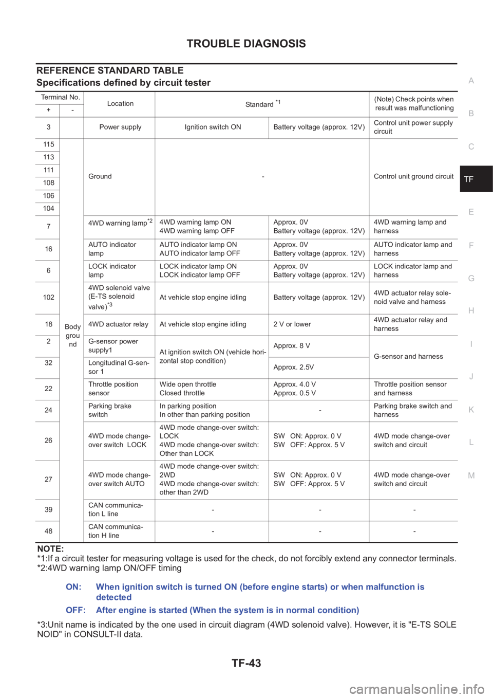
TROUBLE DIAGNOSIS
TF-43
C
E
F
G
H
I
J
K
L
MA
B
TF
REFERENCE STANDARD TABLE
Specifications defined by circuit tester
NOTE:
*1:If a circuit tester for measuring voltage is used for the check, do not forcibly extend any connector terminals.
*2:4WD warning lamp ON/OFF timing
*3:Unit name is indicated by the one used in circuit diagram (4WD solenoid valve). However, it is "E-TS SOLE
NOID" in CONSULT-II data.
Terminal No.
Location
Standard *1(Note) Check points when
result was malfunctioning
+-
3 Power supply Ignition switch ON Battery voltage (approx. 12V)Control unit power supply
circuit
11 5
Body
grou
ndGround - Control unit ground circuit 11 3
111
108
106
104
74WD warning lamp
*24WD warning lamp ON
4WD warning lamp OFFApprox. 0V
Battery voltage (approx. 12V)4WD warning lamp and
harness
16AUTO indicator
lampAUTO indicator lamp ON
AUTO indicator lamp OFFApprox. 0V
Battery voltage (approx. 12V)AUTO indicator lamp and
harness
6LOCK indicator
lampLOCK indicator lamp ON
LOCK indicator lamp OFFApprox. 0V
Battery voltage (approx. 12V)LOCK indicator lamp and
harness
1024WD solenoid valve
(E-TS solenoid
valve)
*3At vehicle stop engine idling Battery voltage (approx. 12V)4WD actuator relay sole-
noid valve and harness
18 4WD actuator relay At vehicle stop engine idling 2 V or lower4WD actuator relay and
harness
2 G-sensor power
supply1
At ignition switch ON (vehicle hori-
zontal stop condition)Approx. 8 V
G-sensor and harness
32 Longitudinal G-sen-
sor 1Approx. 2.5V
22Throttle position
sensorWide open throttle
Closed throttleApprox. 4.0 V
Approx. 0.5 VThrottle position sensor
and harness
24Parking brake
switchIn parking position
In other than parking position-Parking brake switch and
harness
264WD mode change-
over switch LOCK4WD mode change-over switch:
LOCK
4WD mode change-over switch:
Other than LOCKSW ON: Approx. 0 V
SW OFF: Approx. 5 V4WD mode change-over
switch and circuit
274WD mode change-
over switch AUTO4WD mode change-over switch:
2WD
4WD mode change-over switch:
other than 2WDSW ON: Approx. 0 V
SW OFF: Approx. 5 V4WD mode change-over
switch and circuit
39CAN communica-
tion L line---
48CAN communica-
tion H line---
ON: When ignition switch is turned ON (before engine starts) or when malfunction is
detected
OFF: After engine is started (When the system is in normal condition)
![NISSAN X-TRAIL 2001 Service Repair Manual AT-72
[EURO-OBD]
TROUBLE DIAGNOSIS — BASIC INSPECTION
3. CHECK VEHICLE MOVE
1. Turn ignition switch to “OFF” position.
2. Move selector lever to “P” position.
3. Release parking brake.
4. Pu](/manual-img/5/57405/w960_57405-2149.png "NISSAN X-TRAIL 2001 Service Repair Manual AT-72
[EURO-OBD]
TROUBLE DIAGNOSIS — BASIC INSPECTION
3. CHECK VEHICLE MOVE
1. Turn ignition switch to “OFF” position.
2. Move selector lever to “P” position.
3. Release parking brake.
4. Pu")
![NISSAN X-TRAIL 2001 Service Repair Manual AT-268
[EXC.F/EURO-OBD]
TROUBLE DIAGNOSIS — BASIC INSPECTION
Line Pressure Test
ECS004VT
LINE PRESSURE TEST PORTS
Location of line pressure test ports are shown in the illustration.
●Always repla](/manual-img/5/57405/w960_57405-2345.png "NISSAN X-TRAIL 2001 Service Repair Manual AT-268
[EXC.F/EURO-OBD]
TROUBLE DIAGNOSIS — BASIC INSPECTION
Line Pressure Test
ECS004VT
LINE PRESSURE TEST PORTS
Location of line pressure test ports are shown in the illustration.
●Always repla")
![NISSAN X-TRAIL 2001 Service Repair Manual AT-406
[ALL]
A/T SHIFT LOCK SYSTEM
A/T SHIFT LOCK SYSTEM
PFP:34950
DescriptionECS00405
●The mechanical key interlock mechanism also operates as a shift lock:
With the key switch turned to ON, the se](/manual-img/5/57405/w960_57405-2483.png "NISSAN X-TRAIL 2001 Service Repair Manual AT-406
[ALL]
A/T SHIFT LOCK SYSTEM
A/T SHIFT LOCK SYSTEM
PFP:34950
DescriptionECS00405
●The mechanical key interlock mechanism also operates as a shift lock:
With the key switch turned to ON, the se")
![NISSAN X-TRAIL 2001 Service Repair Manual AT-420
[ALL]
REMOVAL AND INSTALLATION
3. Tighten belts fixing transaxle.
4. Reinstall any part removed.
5. Adjust control cable. Refer to AT- 4 1 6 , "
Control Cable Adjust-
ment" .
6.](/manual-img/5/57405/w960_57405-2497.png "NISSAN X-TRAIL 2001 Service Repair Manual AT-420
[ALL]
REMOVAL AND INSTALLATION
3. Tighten belts fixing transaxle.
4. Reinstall any part removed.
5. Adjust control cable. Refer to AT- 4 1 6 , \"
Control Cable Adjust-
ment\" .
6.")