2001 NISSAN X-TRAIL engine mechanical
[x] Cancel search: engine mechanicalPage 1 of 3833

MODEL T30 SERIES
© 2002 NISSAN EUROPE S.A.S.
All rights reserved. No part of this Electronic Service Manual may be reproduced or stored in a retrieval system, or transmitted in any
form, or by any means, electronic, mechanical, photocopying, recording or otherwise, without the prior written permission of Nissan
Europe S.A.S., Paris, France.
A GENERAL INFORMATION
B ENGINE
C TRANSMISSION/
TRANSAXLE
D DRIVELINE/AXLE
E SUSPENSION
F BRAKES
G STEERING
H RESTRAINTS
IBODY
J AIR CONDITIONER
K ELECTRICAL
L MAINTENANCE
M INDEXGI General Information
EM Engine Mechanical
LU Engine Lubrication System
CO Engine Cooling System
EC Engine Control System
FL Fuel System
EX Exhaust System
ACC Accelerator Control System
CL Clutch
MT Manual Transaxle
AT Automatic Transaxle
TF Transfer
PR Propeller Shaft
RFD Rear Final Drive
FAX Front Axle
RAX Rear Axle
FSU Front Suspension
RSU Rear Suspension
WT Road Wheels & Tires
BR Brake System
PB Parking Brake System
BRC Brake Control System
PS Power Steering System
SB Seat Belts
SRS Supplemental Restraint System (SRS)
BL Body, Lock & Security System
GW Glasses, Window System & Mirrors
RF Roof
EI Exterior & Interior
IP Instrument Panel
SE Seat
ATC Automatic Air Conditioner
MTC Manual AIr Conditioner
SC Starting & Charging System
LT Lighting System
DI Driver Information System
WW Wiper, Washer & Horn
BCS Body Control System
LAN LAN System
AV Audio, Visual & Telephone System
PG Power Supply, Ground & Circuit Elements
MA Maintenance
IDX Alphabetical Index
QUICK REFERENCE INDEX
A
B
C
D
E
F
G
H
I
J
K
L
M
Page 25 of 3833
SERVICE INFORMATION FOR ELECTRICAL INCIDENT
GI-23
C
D
E
F
G
H
I
J
K
L
MB
GI
SERVICE INFORMATION FOR ELECTRICAL INCIDENTPFP:00000
How to Perform Efficient Diagnosis for an Electrical IncidentEAS000G6
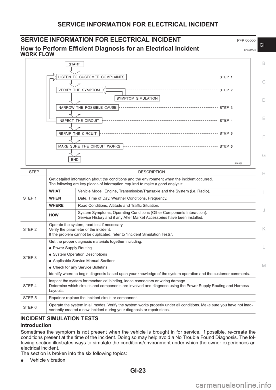
WORK FLOW
INCIDENT SIMULATION TESTS
Introduction
Sometimes the symptom is not present when the vehicle is brought in for service. If possible, re-create the
conditions present at the time of the incident. Doing so may help avoid a No Trouble Found Diagnosis. The fol-
lowing section illustrates ways to simulate the conditions/environment under which the owner experiences an
electrical incident.
The section is broken into the six following topics:
●Vehicle vibration
SGI838
STEP DESCRIPTION
STEP 1Get detailed information about the conditions and the environment when the incident occurred.
The following are key pieces of information required to make a good analysis:
WHATVehicle Model, Engine, Transmission/Transaxle and the System (i.e. Radio).
WHENDate, Time of Day, Weather Conditions, Frequency.
WHERERoad Conditions, Altitude and Traffic Situation.
HOWSystem Symptoms, Operating Conditions (Other Components Interaction).
Service History and if any After Market Accessories have been installed.
STEP 2Operate the system, road test if necessary.
Verify the parameter of the incident.
If the problem cannot be duplicated, refer to “Incident Simulation Tests”.
STEP 3Get the proper diagnosis materials together including:
●Power Supply Routing
●System Operation Descriptions
●Applicable Service Manual Sections
●Check for any Service Bulletins
Identify where to begin diagnosis based upon your knowledge of the system operation and the customer comments.
STEP 4Inspect the system for mechanical binding, loose connectors or wiring damage.
Determine which circuits and components are involved and diagnose using the Power Supply Routing and Harness
Layouts.
STEP 5 Repair or replace the incident circuit or component.
STEP 6Operate the system in all modes. Verify the system works properly under all conditions. Make sure you have not inad-
vertently created a new incident during your diagnosis or repair steps.
Page 51 of 3833
EM-1
ENGINE MECHANICAL
B ENGINE
CONTENTS
C
D
E
F
G
H
I
J
K
L
M
SECTION
A
EM
ENGINE MECHANICAL
QR
PRECAUTIONS .......................................................... 5
Precautions for Drain Engine Coolant ...................... 5
Precautions for Disconnecting Fuel Piping .............. 5
Precautions for Removal and Disassembly ............. 5
Precautions for Inspection, Repair and Replace-
ment ......................................................................... 5
Precautions for Assembly and Installation ............... 5
Parts Requiring Angular Tightening ......................... 5
Precautions For Liquid Gasket ................................. 6
REMOVAL OF LIQUID GASKET .......................... 6
LIQUID GASKET APPLICATION PROCEDURE ..... 6
PREPARATION ........................................................... 7
Special Service Tools ............................................... 7
Commercial Service Tools ........................................ 8
NOISE, VIBRATION, AND HARSHNESS (NVH)
TROUBLESHOOTING .............................................. 10
NVH Troubleshooting —Engine Noise ................... 10
Use the Chart Below to Help You Find the Cause
of the Symptom. ...................................................... 11
DRIVE BELTS ........................................................... 12
Checking Drive Belts .............................................. 12
Tension Adjustment ................................................ 12
Removal and Installation ........................................ 12
REMOVAL ........................................................... 12
INSTALLATION ................................................... 13
Removal and Installation of Drive Belt Auto-Ten-
sioner ..................................................................... 13
REMOVAL ........................................................... 13
INSTALLATION ................................................... 13
AIR CLEANER AND AIR DUCT ............................... 14
Removal and Installation ........................................ 14
REMOVAL ........................................................... 14
INSTALLATION ................................................... 14
CHANGING AIR CLEANER FILTER ................... 15INTAKE MANIFOLD ................................................. 16
Removal and Installation ........................................ 16
QR20DE .............................................................. 16
QR25DE .............................................................. 17
REMOVAL ........................................................... 17
INSPECTION AFTER REMOVAL ....................... 20
INSTALLATION ................................................... 20
INSPECTION AFTER INSTALLATION ................ 22
EXHAUST MANIFOLD AND THREE WAY CATA-
LYST .......................................................................... 24
Removal and Installation ........................................ 24
REMOVAL ........................................................... 24
INSPECTION AFTER REMOVAL ....................
... 25
INSTALLATION ................................................... 25
OIL PAN AND OIL STRAINER ................................. 26
Removal and Installation ........................................ 26
REMOVAL ........................................................... 26
INSPECTION AFTER REMOVAL ....................... 27
INSTALLATION ................................................... 27
INSPECTION AFTER INSTALLATION ................ 28
IGNITION COIL ......................................................... 29
Removal and Installation ........................................ 29
REMOVAL ........................................................... 29
INSTALLATION ................................................... 29
SPARK PLUG ........................................................... 30
Removal and Installation ........................................ 30
REMOVAL ........................................................... 30
INSPECTION AFTER REMOVAL ....................... 30
INSTALLATION ................................................... 31
FUEL INJECTOR AND FUEL TUBE ........................ 32
Removal and Installation ........................................ 32
QR20DE .............................................................. 32
QR25DE .............................................................. 32
REMOVAL ........................................................... 33
INSTALLATION ................................................... 33
INSPECTION AFTER INSTALLATION ................ 34
ROCKER COVER ..................................................... 35
Removal and Installation ........................................ 35
REMOVAL ........................................................... 35
INSTALLATION ................................................... 36
Page 419 of 3833

TROUBLE DIAGNOSIS
EC-69
[QR25(WITH EURO-OBD)]
C
D
E
F
G
H
I
J
K
L
MA
EC
Description for Work Flow
DIAGNOSTIC WORKSHEET
Description
There are many operating conditions that lead to the malfunction of
engine components. A good grasp of such conditions can make trou-
bleshooting faster and more accurate.
In general, each customer feels differently about a problem. It is
important to fully understand the symptoms or conditions for a cus-
tomer complaint.
Utilize a diagnostic worksheet like the one on the next page in order
to organize all the information for troubleshooting.
Some conditions may cause the MI to come on steady or blink and
DTC to be detected. Examples:
●Vehicle ran out of fuel, which caused the engine to misfire.
STEP DESCRIPTION
STEP IGet detailed information about the conditions and the environment when the incident/symptom occurred using the
“DIAGNOSTIC WORK SHEET”, EC-69
.
STEP IIBefore confirming the concern, check and write down (print out using CONSULT-II or GST) the (1st trip) DTC and the
(1st trip) freeze frame data, then erase the DTC and the data. (Refer to EC-56
.) The (1st trip) DTC and the (1st trip)
freeze frame data can be used when duplicating the incident at STEP III & IV.
If the incident cannot be verified, perform EC-115, "
TROUBLE DIAGNOSIS FOR INTERMITTENT INCIDENT" .
Study the relationship between the cause, specified by (1st trip) DTC, and the symptom described by the customer.
(The “Symptom Matrix Chart” will be useful. See EC-77
.)
Also check related service bulletins for information.
STEP IIITry to confirm the symptom and under what conditions the incident occurs.
The “DIAGNOSTIC WORK SHEET” and the freeze frame data are useful to verify the incident. Connect CONSULT-II
to the vehicle in DATA MONITOR (AUTO TRIG) mode and check real time diagnosis results.
If the incident cannot be verified, perform EC-115, "
TROUBLE DIAGNOSIS FOR INTERMITTENT INCIDENT" .
If the malfunction code is detected, skip STEP IV and perform STEP V.
STEP IVTry to detect the (1st trip) DTC by driving in (or performing) the “DTC Confirmation Procedure”. Check and read the
(1st trip) DTC and (1st trip) freeze frame data by using CONSULT-II or GST.
During the (1st trip) DTC verification, be sure to connect CONSULT-II to the vehicle in DATA MONITOR (AUTO TRIG)
mode and check real time diagnosis results.
If the incident cannot be verified, perform EC-115, "
TROUBLE DIAGNOSIS FOR INTERMITTENT INCIDENT" .
In case the “DTC Confirmation Procedure” is not available, perform the “Overall Function Check” instead. The (1st
trip) DTC cannot be displayed by this check, however, this simplified “check” is an effective alternative.
The “NG” result of the “Overall Function Check” is the same as the (1st trip) DTC detection.
STEP VTake the appropriate action based on the results of STEP I through IV.
If the malfunction code is indicated, proceed to TROUBLE DIAGNOSIS FOR DTC PXXXX.
If the normal code is indicated, proceed to the BASIC INSPECTION. (Refer to EC-73
.) Then perform inspections
according to the Symptom Matrix Chart. (Refer to EC-77
.)
STEP VIIdentify where to begin diagnosis based on the relationship study between symptom and possible causes. Inspect the
system for mechanical binding, loose connectors or wiring damage using (tracing) “Harness Layouts”.
Gently shake the related connectors, components or wiring harness with CONSULT-II set in “DATA MONITOR
(AUTO TRIG)” mode.
Check the voltage of the related ECM terminals or monitor the output data from the related sensors with CONSULT-II.
Refer to EC-819
, EC-106 .
The “Diagnostic Procedure” in EC section contains a description based on open circuit inspection. A short circuit
inspection is also required for the circuit check in the Diagnostic Procedure. For details, refer to “Circuit Inspection” in
GI-23, "
How to Perform Efficient Diagnosis for an Electrical Incident" .
Repair or replace the malfunction parts.
If malfunctioning part cannot be detected, perform EC-115, "
TROUBLE DIAGNOSIS FOR INTERMITTENT INCI-
DENT" .
STEP VIIOnce you have repaired the circuit or replaced a component, you need to run the engine in the same conditions and
circumstances which resulted in the customer's initial complaint.
Perform the “DTC Confirmation Procedure” and confirm the normal code [DTC No. P0000] is detected. If the incident
is still detected in the final check, perform STEP VI by using a method different from the previous one.
Before returning the vehicle to the customer, be sure to erase the unnecessary (already fixed) (1st trip) DTC in ECM
and TCM (Transmission control module). (Refer to EC-56, "
HOW TO ERASE EMISSION-RELATED DIAGNOSTIC
INFORMATION" and AT-39, "HOW TO ERASE DTC" .)
SEF907L
Page 423 of 3833

TROUBLE DIAGNOSIS
EC-73
[QR25(WITH EURO-OBD)]
C
D
E
F
G
H
I
J
K
L
MA
EC
Basic InspectionEBS00M0V
1.INSPECTION START
1. Check service records for any recent repairs that may indicate a related incident, or a current need for
scheduled maintenance.
2. Open engine hood and check the following:
–Harness connectors for improper connections
–Wiring harness for improper connections, pinches and cut
–Vacuum hoses for splits, kinks and improper connections
–Hoses and ducts for leaks
–Air cleaner clogging
–Gasket
3. Confirm that electrical or mechanical loads are not applied.
–Headlamp switch is OFF.
–Air conditioner switch is OFF.
–Rear window defogger switch is OFF.
–Steering wheel is in the straight-ahead position, etc.
4. Start engine and warm it up until engine coolant temperature
indicator points the middle of gauge.
Ensure engine stays below 1,000 rpm.
5. Run engine at about 2,000 rpm for about 2 minutes under no-
load.
6. Make sure that no DTC is displayed with CONSULT-II or GST.
OK or NG
OK >> GO TO 3.
NG >> GO TO 2.
2.REPAIR OR REPLACE
Repair or replace components as necessary according to corresponding “Diagnostic Procedure”.
>> GO TO 3
SEF983U
SEF976U
SEF977U
Page 429 of 3833

TROUBLE DIAGNOSIS
EC-79
[QR25(WITH EURO-OBD)]
C
D
E
F
G
H
I
J
K
L
MA
EC
(continued on next page)
SYSTEM — ENGINE MECHANICAL & OTHER
SYMPTOM
Reference
page
HARD/NO START/RESTART (EXCP. HA)
ENGINE STALL
HESITATION/SURGING/FLAT SPOT
SPARK KNOCK/DETONATION
LACK OF POWER/POOR ACCELERATION
HIGH IDLE/LOW IDLE
ROUGH IDLE/HUNTING
IDLING VIBRATION
SLOW/NO RETURN TO IDLE
OVERHEATS/WATER TEMPERATURE HIGH
EXCESSIVE FUEL CONSUMPTION
EXCESSIVE OIL CONSUMPTION
BATTERY DEAD (UNDER CHARGE)
Warranty symptom code AA AB AC AD AE AF AG AH AJ AK AL AM HA
Fuel Fuel tank
5
5FL-9
Fuel piping 5 5 5 5 5 5FL-3,EM-
32
Vapor lock—
Valve deposit
555555 5—
Poor fuel (Heavy weight gaso-
line, Low octane)—
Air Air duct
55555 5EM-14
Air cleanerEM-14
Air leakage from air duct
(Mass air flow sensor —electric
throttle control actuator)
5555EM-14
Electric throttle control actuatorEM-16
Air leakage from intake manifold/
Collector/GasketEM-16
Cranking Battery
111111 11SC-3
Alternator circuitSC-12
Starter circuit 3SC-20
Signal plate 6EM-73
PNP switch
4MT-12 or
AT- 11 5
Engine Cylinder head
55555 55 5EM-59
Cylinder head gasket 4 3
Cylinder block
66666 66 64
EM-73
Piston
Piston ring
Connecting rod
Bearing
Crankshaft
Page 812 of 3833

EC-462
[QR25(WITHOUT EURO-OBD)]
TROUBLE DIAGNOSIS
Description for Work Flow
DIAGNOSTIC WORKSHEET
Description
There are many operating conditions that lead to the malfunction of
engine components. A good grasp of such conditions can make trou-
bleshooting faster and more accurate.
In general, each customer feels differently about an incident. It is
important to fully understand the symptoms or conditions for a cus-
tomer complaint.
Utilize a diagnostic worksheet like the one on the next page in order
to organize all the information for troubleshooting.
Some conditions may cause the MI to come on steady or blink and
DTC to be detected. Examples:
●Vehicle ran out of fuel, which caused the engine to misfire.
STEP DESCRIPTION
STEP IGet detailed information about the conditions and the environment when the incident/symptom occurred using the
“DIAGNOSTIC WORK SHEET”, EC-462
.
STEP IIBefore confirming the concern, check and write down (print out using CONSULT-II or GST) the (1st trip) DTC and the
(1st trip) freeze frame data, then erase the DTC and the data. (Refer to EC-455
.) The (1st trip) DTC and the (1st trip)
freeze frame data can be used when duplicating the incident at STEP III & IV.
If the incident cannot be verified, perform EC-506, "
TROUBLE DIAGNOSIS FOR INTERMITTENT INCIDENT" .
Study the relationship between the cause, specified by (1st trip) DTC, and the symptom described by the customer.
(The “Symptom Matrix Chart” will be useful. See EC-469
.)
Also check related service bulletins for information.
STEP IIITry to confirm the symptom and under what conditions the incident occurs.
The “DIAGNOSTIC WORK SHEET” and the freeze frame data are useful to verify the incident. Connect CONSULT-II
to the vehicle in DATA MONITOR (AUTO TRIG) mode and check real time diagnosis results.
If the incident cannot be verified, perform EC-506, "
TROUBLE DIAGNOSIS FOR INTERMITTENT INCIDENT" .
If the malfunction code is detected, skip STEP IV and perform STEP V.
STEP IVTry to detect the (1st trip) DTC by driving in (or performing) the “DTC Confirmation Procedure”. Check and read the
(1st trip) DTC and (1st trip) freeze frame data by using CONSULT-II or GST.
During the (1st trip) DTC verification, be sure to connect CONSULT-II to the vehicle in DATA MONITOR (AUTO TRIG)
mode and check real time diagnosis results.
If the incident cannot be verified, perform EC-506, "
TROUBLE DIAGNOSIS FOR INTERMITTENT INCIDENT" .
In case the “DTC Confirmation Procedure” is not available, perform the “Overall Function Check” instead. The (1st
trip) DTC cannot be displayed by this check, however, this simplified “check” is an effective alternative.
The “NG” result of the “Overall Function Check” is the same as the (1st trip) DTC detection.
STEP VTake the appropriate action based on the results of STEP I through IV.
If the malfunction code is indicated, proceed to TROUBLE DIAGNOSIS FOR DTC PXXXX.
If the normal code is indicated, proceed to the BASIC INSPECTION. (Refer to EC-465
.) Then perform inspections
according to the Symptom Matrix Chart. (Refer to EC-469
.)
STEP VIIdentify where to begin diagnosis based on the relationship study between symptom and possible causes. Inspect the
system for mechanical binding, loose connectors or wiring damage using (tracing) “Harness Layouts”.
Gently shake the related connectors, components or wiring harness with CONSULT-II set in “DATA MONITOR
(AUTO TRIG)” mode.
Check the voltage of the related ECM terminals or monitor the output data from the related sensors with CONSULT-II.
Refer to EC-479
, EC-496 .
The “Diagnostic Procedure” in EC section contains a description based on open circuit inspection. A short circuit
inspection is also required for the circuit check in the Diagnostic Procedure. For details, refer to “Circuit Inspection” in
GI-23, "
How to Perform Efficient Diagnosis for an Electrical Incident" .
Repair or replace the malfunction parts.
If malfunctioning part cannot be detected, perform EC-506, "
TROUBLE DIAGNOSIS FOR INTERMITTENT INCI-
DENT" .
STEP VIIOnce you have repaired the circuit or replaced a component, you need to run the engine in the same conditions and
circumstances which resulted in the customer's initial complaint.
Perform the “DTC Confirmation Procedure” and confirm the normal code [DTC No. P0000] is detected. If the incident
is still detected in the final check, perform STEP VI by using a method different from the previous one.
Before returning the vehicle to the customer, be sure to erase the unnecessary (already fixed) (1st trip) DTC in ECM.
(Refer to EC-455, "
HOW TO ERASE EMISSION-RELATED DIAGNOSTIC INFORMATION" .)
SEF907L
Page 815 of 3833

TROUBLE DIAGNOSIS
EC-465
[QR25(WITHOUT EURO-OBD)]
C
D
E
F
G
H
I
J
K
L
MA
EC
Basic InspectionEBS00NEC
1.INSPECTION START
1. Check service records for any recent repairs that may indicate a related incident, or a current need for
scheduled maintenance.
2. Open engine hood and check the following:
–Harness connectors for improper connections
–Wiring harness for improper connections, pinches and cut
–Vacuum hoses for splits, kinks and improper connections
–Hoses and ducts for leaks
–Air cleaner clogging
–Gasket
3. Confirm that electrical or mechanical loads are not applied.
–Headlamp switch is OFF.
–Air conditioner switch is OFF.
–Rear window defogger switch is OFF.
–Steering wheel is in the straight-ahead position, etc.
4. Start engine and warm it up until engine coolant temperature
indicator points the middle of gauge.
Ensure engine stays below 1,000 rpm.
5. Run engine at about 2,000 rpm for about 2 minutes under no-
load.
6. Make sure that no DTC is displayed with CONSULT-II or GST.
OK or NG
OK >> GO TO 3.
NG >> GO TO 2.
2.REPAIR OR REPLACE
Repair or replace components as necessary according to corresponding “Diagnostic Procedure”.
>> GO TO 3.
P1229 Sensor power supply ECM stops the electric throttle control actuator control, throttle valve is maintained at a
fixed opening (approx. 5 degrees) by the return spring.
P2122
P2123
P2127
P2128
P2138Accelerator pedal position
sensorThe ECM controls the electric throttle control actuator in regulating the throttle opening
in order for the idle position to be within +10 degrees.
The ECM regulates the opening speed of the throttle valve to be slower than the nor-
mal condition.
So, the acceleration will be poor. DTC No. Detected items Engine operating condition in fail-safe mode
SEF983U
SEF976U
SEF977U