2001 NISSAN PICK-UP Steering diagram
[x] Cancel search: Steering diagramPage 29 of 1306
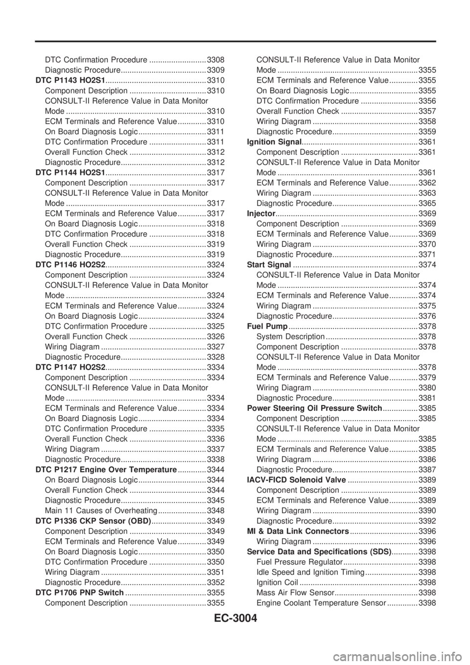
DTC Confirmation Procedure .......................... 3308
Diagnostic Procedure....................................... 3309
DTC P1143 HO2S1.............................................. 3310
Component Description ................................... 3310
CONSULT-II Reference Value in Data Monitor
Mode ................................................................ 3310
ECM Terminals and Reference Value ............. 3310
On Board Diagnosis Logic ............................... 3311
DTC Confirmation Procedure .......................... 3311
Overall Function Check ................................... 3312
Diagnostic Procedure....................................... 3312
DTC P1144 HO2S1.............................................. 3317
Component Description ................................... 3317
CONSULT-II Reference Value in Data Monitor
Mode ................................................................ 3317
ECM Terminals and Reference Value ............. 3317
On Board Diagnosis Logic ............................... 3318
DTC Confirmation Procedure .......................... 3318
Overall Function Check ................................... 3319
Diagnostic Procedure....................................... 3319
DTC P1146 HO2S2.............................................. 3324
Component Description ................................... 3324
CONSULT-II Reference Value in Data Monitor
Mode ................................................................ 3324
ECM Terminals and Reference Value ............. 3324
On Board Diagnosis Logic ............................... 3324
DTC Confirmation Procedure .......................... 3325
Overall Function Check ................................... 3326
Wiring Diagram ................................................ 3327
Diagnostic Procedure....................................... 3328
DTC P1147 HO2S2.............................................. 3334
Component Description ................................... 3334
CONSULT-II Reference Value in Data Monitor
Mode ................................................................ 3334
ECM Terminals and Reference Value ............. 3334
On Board Diagnosis Logic ............................... 3334
DTC Confirmation Procedure .......................... 3335
Overall Function Check ................................... 3336
Wiring Diagram ................................................ 3337
Diagnostic Procedure....................................... 3338
DTC P1217 Engine Over Temperature............. 3344
On Board Diagnosis Logic ............................... 3344
Overall Function Check ................................... 3344
Diagnostic Procedure....................................... 3345
Main 11 Causes of Overheating ...................... 3348
DTC P1336 CKP Sensor (OBD)......................... 3349
Component Description ................................... 3349
ECM Terminals and Reference Value ............. 3349
On Board Diagnosis Logic ............................... 3350
DTC Confirmation Procedure .......................... 3350
Wiring Diagram ................................................ 3351
Diagnostic Procedure....................................... 3352
DTC P1706 PNP Switch..................................... 3355
Component Description ................................... 3355CONSULT-II Reference Value in Data Monitor
Mode ................................................................ 3355
ECM Terminals and Reference Value ............. 3355
On Board Diagnosis Logic ............................... 3355
DTC Confirmation Procedure .......................... 3356
Overall Function Check ................................... 3357
Wiring Diagram ................................................ 3358
Diagnostic Procedure....................................... 3359
Ignition Signal..................................................... 3361
Component Description ................................... 3361
CONSULT-II Reference Value in Data Monitor
Mode ................................................................ 3361
ECM Terminals and Reference Value ............. 3362
Wiring Diagram ................................................ 3363
Diagnostic Procedure....................................... 3365
Injector................................................................. 3369
Component Description ................................... 3369
ECM Terminals and Reference Value ............. 3369
Wiring Diagram ................................................ 3370
Diagnostic Procedure....................................... 3371
Start Signal......................................................... 3374
CONSULT-II Reference Value in Data Monitor
Mode ................................................................ 3374
ECM Terminals and Reference Value ............. 3374
Wiring Diagram ................................................ 3375
Diagnostic Procedure....................................... 3376
Fuel Pump........................................................... 3378
System Description .......................................... 3378
Component Description ................................... 3378
CONSULT-II Reference Value in Data Monitor
Mode ................................................................ 3378
ECM Terminals and Reference Value ............. 3379
Wiring Diagram ................................................ 3380
Diagnostic Procedure....................................... 3381
Power Steering Oil Pressure Switch................ 3385
Component Description ................................... 3385
CONSULT-II Reference Value in Data Monitor
Mode ................................................................ 3385
ECM Terminals and Reference Value ............. 3385
Wiring Diagram ................................................ 3386
Diagnostic Procedure....................................... 3387
IACV-FICD Solenoid Valve................................ 3389
Component Description ................................... 3389
ECM Terminals and Reference Value ............. 3389
Wiring Diagram ................................................ 3390
Diagnostic Procedure....................................... 3392
MI & Data Link Connectors............................... 3396
Wiring Diagram ................................................ 3396
Service Data and Specifications (SDS)............ 3398
Fuel Pressure Regulator .................................. 3398
Idle Speed and Ignition Timing ........................ 3398
Ignition Coil ...................................................... 3398
Mass Air Flow Sensor...................................... 3398
Engine Coolant Temperature Sensor .............. 3398
EC-3004
Page 411 of 1306

Wiring DiagramNEEC0450
GEC257A
POWER STEERING OIL PRESSURE
SWITCH
KA24DE (EURO OBD)
Wiring Diagram
EC-3386
Page 413 of 1306
4 CHECK INPUT SIGNAL CIRCUIT
1. Turn ignition switch ªOFFº.
2. Disconnect ECM harness connector.
3. Check harness continuity between ECM terminal 39 and terminal 1. Refer to wiring diagram.
Continuity should exist.
4. Also check harness for short to ground and short to power.
OK or NG
OK©GO TO 6.
NG©GO TO 5.
5 DETECT MALFUNCTIONING PART
Check the following.
+Harness connectors M5, E101
Check the harness for open or short between ECM and power steering oil pressure switch.
©Repair open circuit or short to ground or short to power in harness or connectors.
6 CHECK GROUND CIRCUIT
1. Disconnect power steering oil pressure switch harness connector.
2. Check continuity between power steering oil pressure switch harness connector terminal 2 and ground.
Continuity should exist.
OK or NG
OK©
NG©Repair open circuit or short to power in harness or connectors.
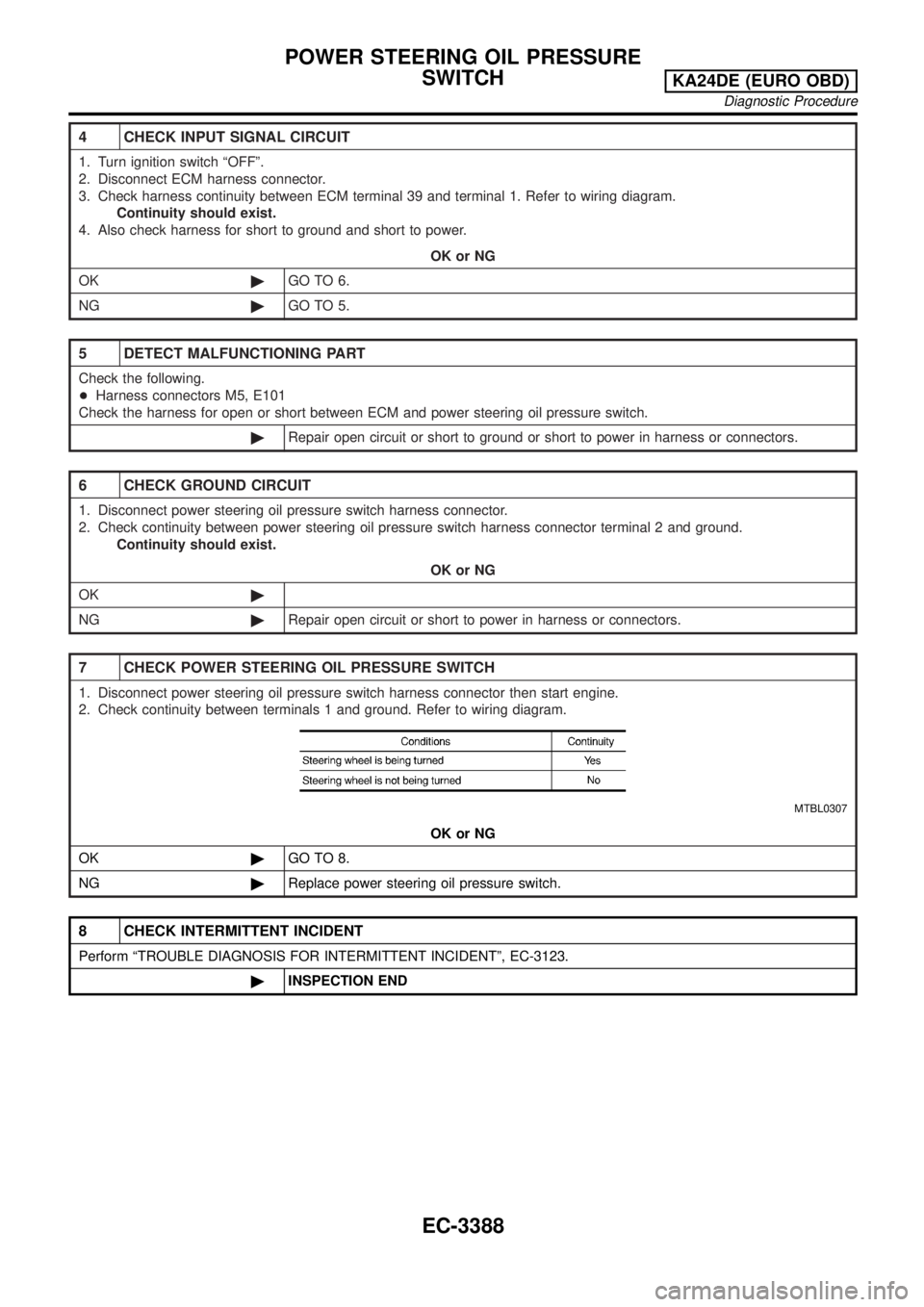
7 CHECK POWER STEERING OIL PRESSURE SWITCH
1. Disconnect power steering oil pressure switch harness connector then start engine.
2. Check continuity between terminals 1 and ground. Refer to wiring diagram.
MTBL0307
OK or NG
OK©GO TO 8.
NG©Replace power steering oil pressure switch.
8 CHECK INTERMITTENT INCIDENT
Perform ªTROUBLE DIAGNOSIS FOR INTERMITTENT INCIDENTº, EC-3123.
©INSPECTION END
POWER STEERING OIL PRESSURE
SWITCH
KA24DE (EURO OBD)
Diagnostic Procedure
EC-3388
Page 870 of 1306
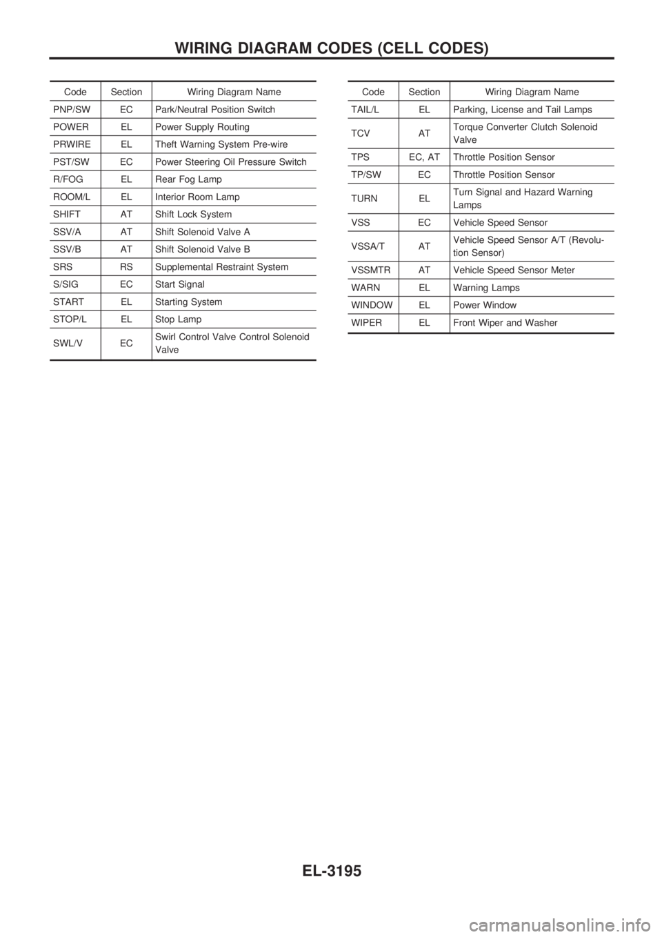
Code Section Wiring Diagram Name
PNP/SW EC Park/Neutral Position Switch
POWER EL Power Supply Routing
PRWIRE EL Theft Warning System Pre-wire
PST/SW EC Power Steering Oil Pressure Switch
R/FOG EL Rear Fog Lamp
ROOM/L EL Interior Room Lamp
SHIFT AT Shift Lock System
SSV/A AT Shift Solenoid Valve A
SSV/B AT Shift Solenoid Valve B
SRS RS Supplemental Restraint System
S/SIG EC Start Signal
START EL Starting System
STOP/L EL Stop Lamp
SWL/V ECSwirl Control Valve Control Solenoid
ValveCode Section Wiring Diagram Name
TAIL/L EL Parking, License and Tail Lamps
TCV ATTorque Converter Clutch Solenoid
Valve
TPS EC, AT Throttle Position Sensor
TP/SW EC Throttle Position Sensor
TURN ELTurn Signal and Hazard Warning
Lamps
VSS EC Vehicle Speed Sensor
VSSA/T ATVehicle Speed Sensor A/T (Revolu-
tion Sensor)
VSSMTR AT Vehicle Speed Sensor Meter
WARN EL Warning Lamps
WINDOW EL Power Window
WIPER EL Front Wiper and Washer
WIRING DIAGRAM CODES (CELL CODES)
EL-3195
Page 1064 of 1306
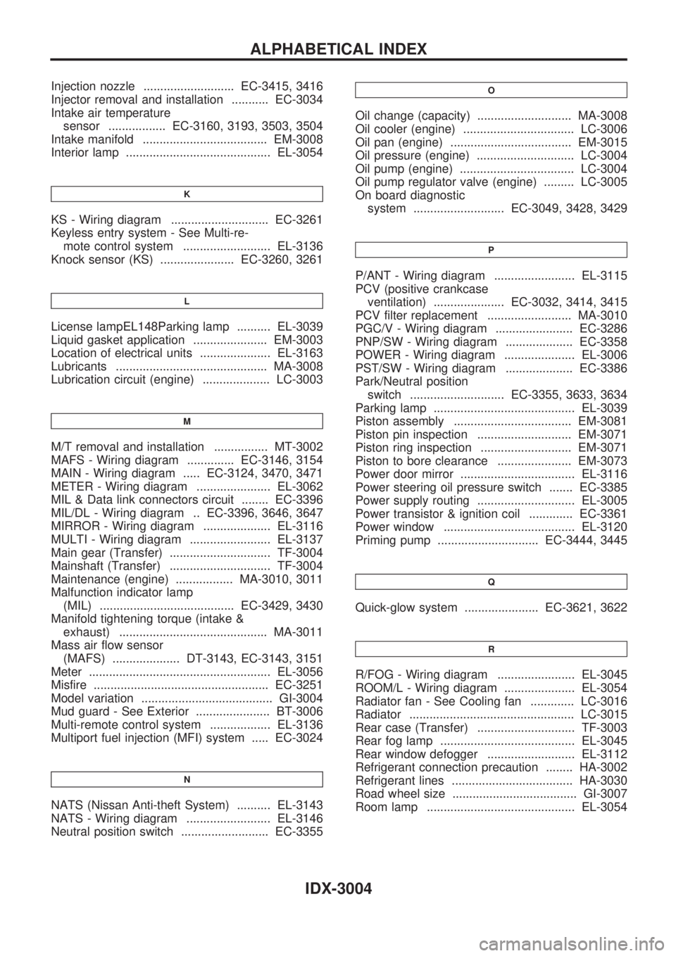
Injection nozzle ........................... EC-3415, 3416
Injector removal and installation ........... EC-3034
Intake air temperature
sensor ................. EC-3160, 3193, 3503, 3504
Intake manifold ..................................... EM-3008
Interior lamp ........................................... EL-3054
K
KS - Wiring diagram ............................. EC-3261
Keyless entry system - See Multi-re-
mote control system .......................... EL-3136
Knock sensor (KS) ...................... EC-3260, 3261
L
License lampEL148Parking lamp .......... EL-3039
Liquid gasket application ...................... EM-3003
Location of electrical units ..................... EL-3163
Lubricants ............................................. MA-3008
Lubrication circuit (engine) .................... LC-3003
M
M/T removal and installation ................ MT-3002
MAFS - Wiring diagram .............. EC-3146, 3154
MAIN - Wiring diagram ..... EC-3124, 3470, 3471
METER - Wiring diagram ...................... EL-3062
MIL & Data link connectors circuit ........ EC-3396
MIL/DL - Wiring diagram .. EC-3396, 3646, 3647
MIRROR - Wiring diagram .................... EL-3116
MULTI - Wiring diagram ........................ EL-3137
Main gear (Transfer) .............................. TF-3004
Mainshaft (Transfer) .............................. TF-3004
Maintenance (engine) ................. MA-3010, 3011
Malfunction indicator lamp
(MIL) ........................................ EC-3429, 3430
Manifold tightening torque (intake &
exhaust) ............................................ MA-3011
Mass air flow sensor
(MAFS) .................... DT-3143, EC-3143, 3151
Meter ...................................................... EL-3056
Misfire .................................................... EC-3251
Model variation ....................................... GI-3004
Mud guard - See Exterior ...................... BT-3006
Multi-remote control system .................. EL-3136
Multiport fuel injection (MFI) system ..... EC-3024
N
NATS (Nissan Anti-theft System) .......... EL-3143
NATS - Wiring diagram ......................... EL-3146
Neutral position switch .......................... EC-3355
O
Oil change (capacity) ............................ MA-3008
Oil cooler (engine) ................................. LC-3006
Oil pan (engine) .................................... EM-3015
Oil pressure (engine) ............................. LC-3004
Oil pump (engine) .................................. LC-3004
Oil pump regulator valve (engine) ......... LC-3005
On board diagnostic
system ........................... EC-3049, 3428, 3429
P
P/ANT - Wiring diagram ........................ EL-3115
PCV (positive crankcase
ventilation) ..................... EC-3032, 3414, 3415
PCV filter replacement ......................... MA-3010
PGC/V - Wiring diagram ....................... EC-3286
PNP/SW - Wiring diagram .................... EC-3358
POWER - Wiring diagram ..................... EL-3006
PST/SW - Wiring diagram .................... EC-3386
Park/Neutral position
switch ............................ EC-3355, 3633, 3634
Parking lamp .......................................... EL-3039
Piston assembly ................................... EM-3081
Piston pin inspection ............................ EM-3071
Piston ring inspection ........................... EM-3071
Piston to bore clearance ...................... EM-3073
Power door mirror .................................. EL-3116
Power steering oil pressure switch ....... EC-3385
Power supply routing ............................. EL-3005
Power transistor & ignition coil ............. EC-3361
Power window ....................................... EL-3120
Priming pump .............................. EC-3444, 3445
Q
Quick-glow system ...................... EC-3621, 3622
R
R/FOG - Wiring diagram ....................... EL-3045
ROOM/L - Wiring diagram ..................... EL-3054
Radiator fan - See Cooling fan ............. LC-3016
Radiator ................................................. LC-3015
Rear case (Transfer) ............................. TF-3003
Rear fog lamp ........................................ EL-3045
Rear window defogger .......................... EL-3112
Refrigerant connection precaution ........ HA-3002
Refrigerant lines .................................... HA-3030
Road wheel size ..................................... GI-3007
Room lamp ............................................ EL-3054
ALPHABETICAL INDEX
IDX-3004
Page 1306 of 1306
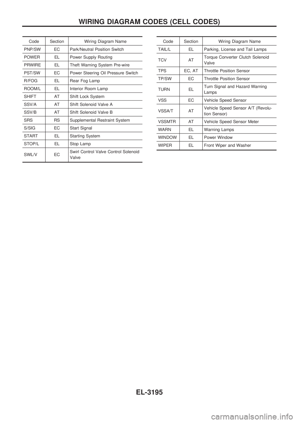
Code Section Wiring Diagram Name
PNP/SW EC Park/Neutral Position Switch
POWER EL Power Supply Routing
PRWIRE EL Theft Warning System Pre-wire
PST/SW EC Power Steering Oil Pressure Switch
R/FOG EL Rear Fog Lamp
ROOM/L EL Interior Room Lamp
SHIFT AT Shift Lock System
SSV/A AT Shift Solenoid Valve A
SSV/B AT Shift Solenoid Valve B
SRS RS Supplemental Restraint System
S/SIG EC Start Signal
START EL Starting System
STOP/L EL Stop Lamp
SWL/V ECSwirl Control Valve Control Solenoid
ValveCode Section Wiring Diagram Name
TAIL/L EL Parking, License and Tail Lamps
TCV ATTorque Converter Clutch Solenoid
Valve
TPS EC, AT Throttle Position Sensor
TP/SW EC Throttle Position Sensor
TURN ELTurn Signal and Hazard Warning
Lamps
VSS EC Vehicle Speed Sensor
VSSA/T ATVehicle Speed Sensor A/T (Revolu-
tion Sensor)
VSSMTR AT Vehicle Speed Sensor Meter
WARN EL Warning Lamps
WINDOW EL Power Window
WIPER EL Front Wiper and Washer
WIRING DIAGRAM CODES (CELL CODES)
EL-3195