2001 NISSAN PICK-UP stop start
[x] Cancel search: stop startPage 124 of 1306
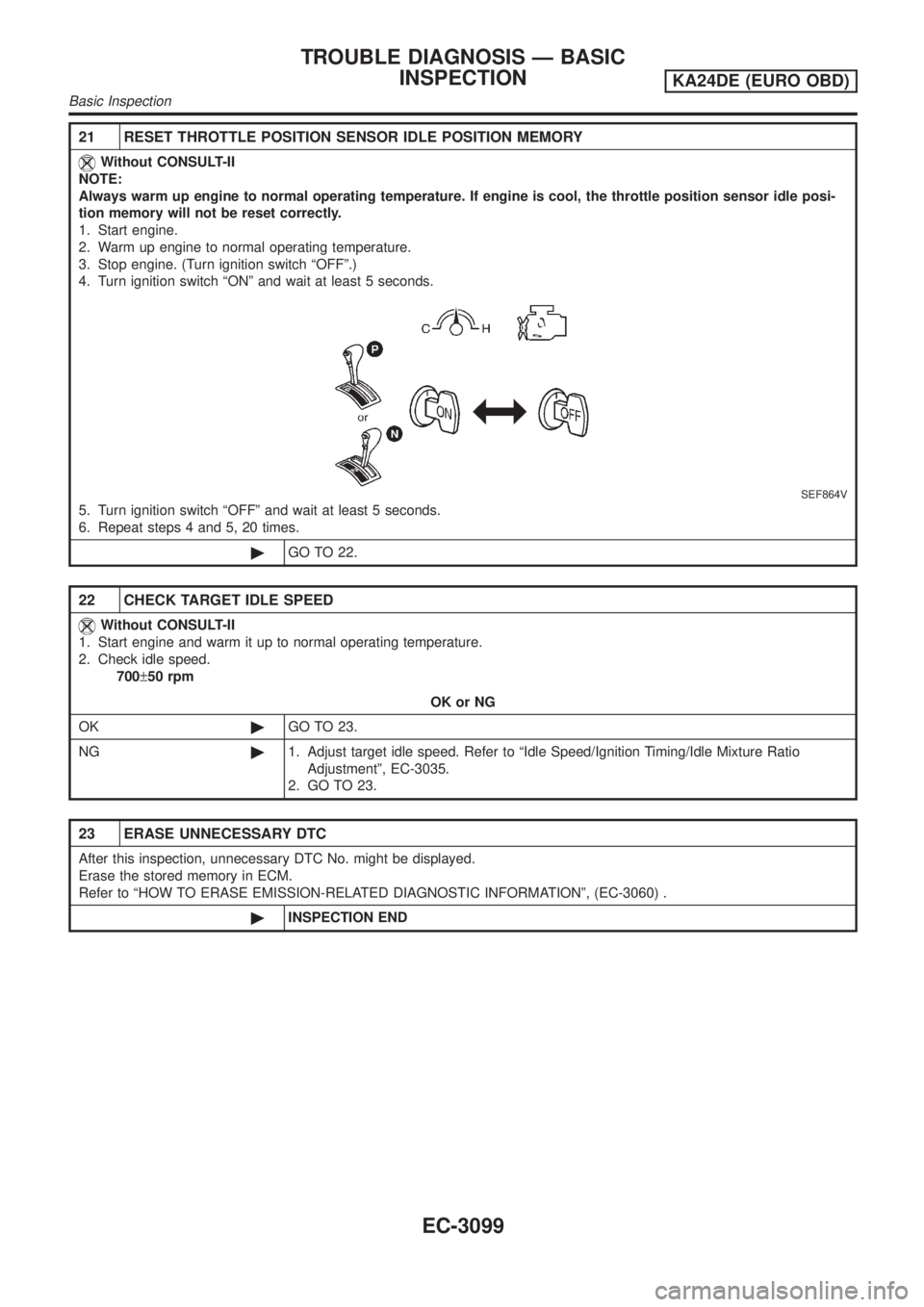
21 RESET THROTTLE POSITION SENSOR IDLE POSITION MEMORY
Without CONSULT-II
NOTE:
Always warm up engine to normal operating temperature. If engine is cool, the throttle position sensor idle posi-
tion memory will not be reset correctly.
1. Start engine.
2. Warm up engine to normal operating temperature.
3. Stop engine. (Turn ignition switch ªOFFº.)
4. Turn ignition switch ªONº and wait at least 5 seconds.
SEF864V
5. Turn ignition switch ªOFFº and wait at least 5 seconds.
6. Repeat steps 4 and 5, 20 times.
©GO TO 22.
22 CHECK TARGET IDLE SPEED
Without CONSULT-II
1. Start engine and warm it up to normal operating temperature.
2. Check idle speed.
700±50 rpm
OK or NG
OK©GO TO 23.
NG©1. Adjust target idle speed. Refer to ªIdle Speed/Ignition Timing/Idle Mixture Ratio
Adjustmentº, EC-3035.
2. GO TO 23.
23 ERASE UNNECESSARY DTC
After this inspection, unnecessary DTC No. might be displayed.
Erase the stored memory in ECM.
Refer to ªHOW TO ERASE EMISSION-RELATED DIAGNOSTIC INFORMATIONº, (EC-3060) .
©INSPECTION END
TROUBLE DIAGNOSIS Ð BASIC
INSPECTION
KA24DE (EURO OBD)
Basic Inspection
EC-3099
Page 131 of 1306
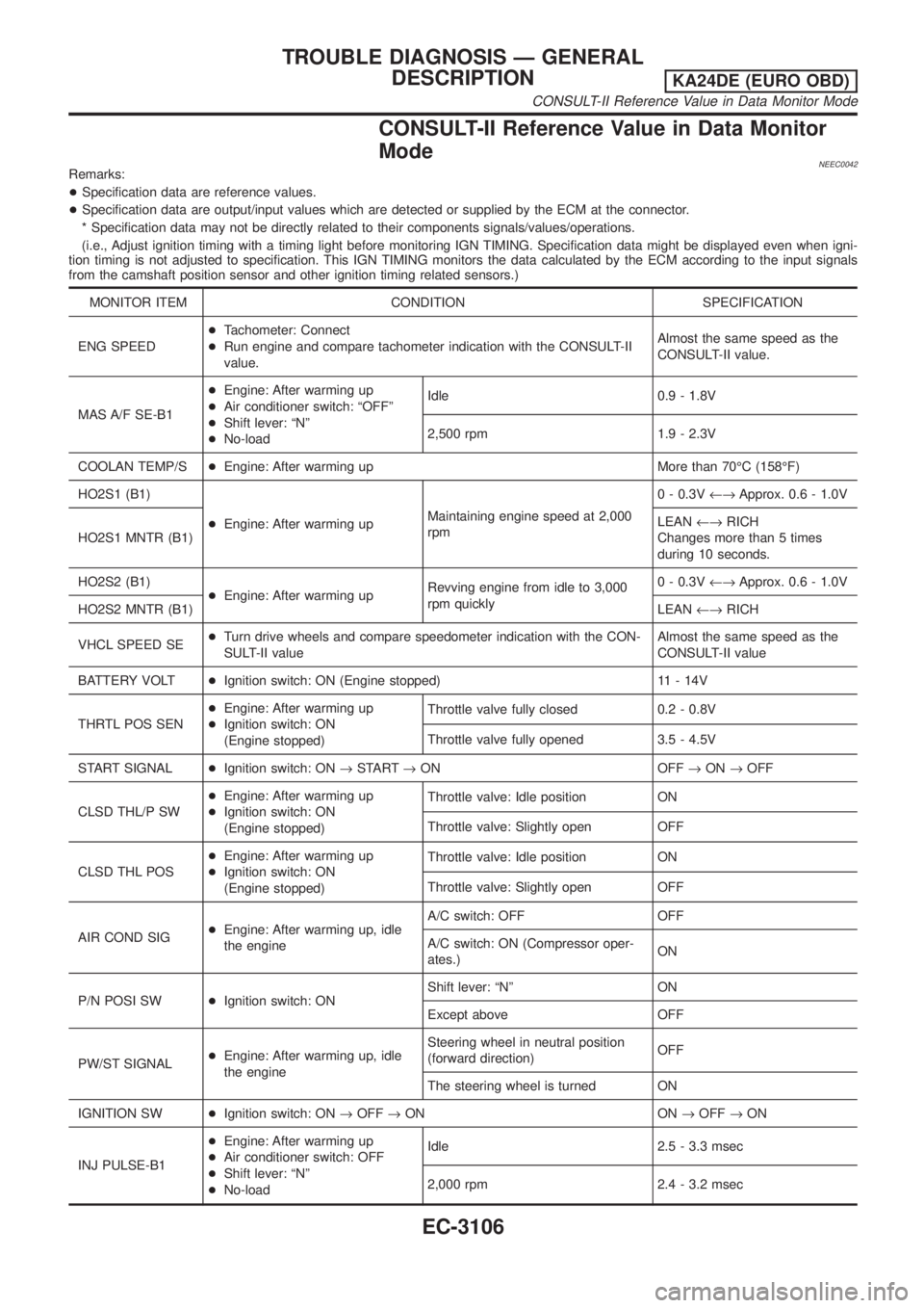
CONSULT-II Reference Value in Data Monitor
Mode
NEEC0042Remarks:
+Specification data are reference values.
+Specification data are output/input values which are detected or supplied by the ECM at the connector.
* Specification data may not be directly related to their components signals/values/operations.
(i.e., Adjust ignition timing with a timing light before monitoring IGN TIMING. Specification data might be displayed even when igni-
tion timing is not adjusted to specification. This IGN TIMING monitors the data calculated by the ECM according to the input signals
from the camshaft position sensor and other ignition timing related sensors.)
MONITOR ITEM CONDITION SPECIFICATION
ENG SPEED+Tachometer: Connect
+Run engine and compare tachometer indication with the CONSULT-II
value.Almost the same speed as the
CONSULT-II value.
MAS A/F SE-B1+Engine: After warming up
+Air conditioner switch: ªOFFº
+Shift lever: ªNº
+No-loadIdle 0.9 - 1.8V
2,500 rpm 1.9 - 2.3V
COOLAN TEMP/S+Engine: After warming up More than 70ÉC (158ÉF)
HO2S1 (B1)
+Engine: After warming upMaintaining engine speed at 2,000
rpm0 - 0.3V¨Approx. 0.6 - 1.0V
HO2S1 MNTR (B1)LEAN¨RICH
Changes more than 5 times
during 10 seconds.
HO2S2 (B1)
+Engine: After warming upRevving engine from idle to 3,000
rpm quickly0 - 0.3V¨Approx. 0.6 - 1.0V
HO2S2 MNTR (B1)LEAN¨RICH
VHCL SPEED SE+Turn drive wheels and compare speedometer indication with the CON-
SULT-II valueAlmost the same speed as the
CONSULT-II value
BATTERY VOLT+Ignition switch: ON (Engine stopped) 11 - 14V
THRTL POS SEN+Engine: After warming up
+Ignition switch: ON
(Engine stopped)Throttle valve fully closed 0.2 - 0.8V
Throttle valve fully opened 3.5 - 4.5V
START SIGNAL+Ignition switch: ON®START®ON OFF®ON®OFF
CLSD THL/P SW+Engine: After warming up
+Ignition switch: ON
(Engine stopped)Throttle valve: Idle position ON
Throttle valve: Slightly open OFF
CLSD THL POS+Engine: After warming up
+Ignition switch: ON
(Engine stopped)Throttle valve: Idle position ON
Throttle valve: Slightly open OFF
AIR COND SIG+Engine: After warming up, idle
the engineA/C switch: OFF OFF
A/C switch: ON (Compressor oper-
ates.)ON
P/N POSI SW+Ignition switch: ONShift lever: ªNº ON
Except above OFF
PW/ST SIGNAL+Engine: After warming up, idle
the engineSteering wheel in neutral position
(forward direction)OFF
The steering wheel is turned ON
IGNITION SW+Ignition switch: ON®OFF®ON ON®OFF®ON
INJ PULSE-B1+Engine: After warming up
+Air conditioner switch: OFF
+Shift lever: ªNº
+No-loadIdle 2.5 - 3.3 msec
2,000 rpm 2.4 - 3.2 msec
TROUBLE DIAGNOSIS Ð GENERAL
DESCRIPTION
KA24DE (EURO OBD)
CONSULT-II Reference Value in Data Monitor Mode
EC-3106
Page 132 of 1306
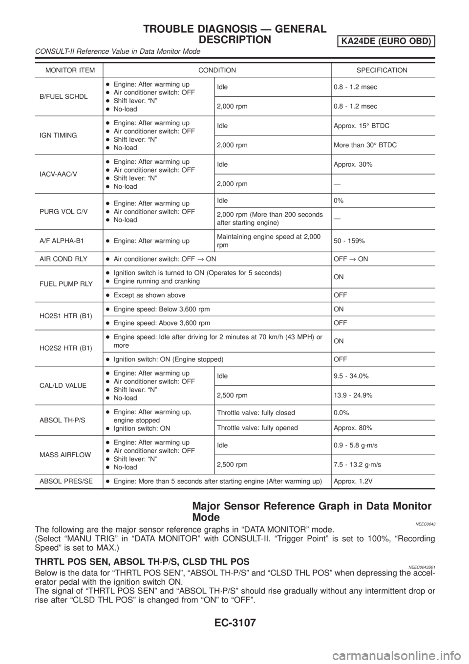
MONITOR ITEM CONDITION SPECIFICATION
B/FUEL SCHDL+Engine: After warming up
+Air conditioner switch: OFF
+Shift lever: ªNº
+No-loadIdle 0.8 - 1.2 msec
2,000 rpm 0.8 - 1.2 msec
IGN TIMING+Engine: After warming up
+Air conditioner switch: OFF
+Shift lever: ªNº
+No-loadIdle Approx. 15É BTDC
2,000 rpm More than 30É BTDC
IACV-AAC/V+Engine: After warming up
+Air conditioner switch: OFF
+Shift lever: ªNº
+No-loadIdle Approx. 30%
2,000 rpm Ð
PURG VOL C/V+Engine: After warming up
+Air conditioner switch: OFF
+No-loadIdle 0%
2,000 rpm (More than 200 seconds
after starting engine)Ð
A/F ALPHA-B1+Engine: After warming upMaintaining engine speed at 2,000
rpm50 - 159%
AIR COND RLY+Air conditioner switch: OFF®ON OFF®ON
FUEL PUMP RLY+Ignition switch is turned to ON (Operates for 5 seconds)
+Engine running and crankingON
+Except as shown above OFF
HO2S1 HTR (B1)+Engine speed: Below 3,600 rpm ON
+Engine speed: Above 3,600 rpm OFF
HO2S2 HTR (B1)+Engine speed: Idle after driving for 2 minutes at 70 km/h (43 MPH) or
moreON
+Ignition switch: ON (Engine stopped) OFF
CAL/LD VALUE+Engine: After warming up
+Air conditioner switch: OFF
+Shift lever: ªNº
+No-loadIdle 9.5 - 34.0%
2,500 rpm 13.9 - 24.9%
ABSOL TH´P/S+Engine: After warming up,
engine stopped
+Ignition switch: ONThrottle valve: fully closed 0.0%
Throttle valve: fully opened Approx. 80%
MASS AIRFLOW+Engine: After warming up
+Air conditioner switch: OFF
+Shift lever: ªNº
+No-loadIdle 0.9 - 5.8 g´m/s
2,500 rpm 7.5 - 13.2 g´m/s
ABSOL PRES/SE+Engine: More than 5 seconds after starting engine (After warming up) Approx. 1.2V
Major Sensor Reference Graph in Data Monitor
Mode
NEEC0043The following are the major sensor reference graphs in ªDATA MONITORº mode.
(Select ªMANU TRIGº in ªDATA MONITORº with CONSULT-II. ªTrigger Pointº is set to 100%, ªRecording
Speedº is set to MAX.)
THRTL POS SEN, ABSOL TH´P/S, CLSD THL POSNEEC0043S01Below is the data for ªTHRTL POS SENº, ªABSOL TH´P/Sº and ªCLSD THL POSº when depressing the accel-
erator pedal with the ignition switch ON.
The signal of ªTHRTL POS SENº and ªABSOL TH´P/Sº should rise gradually without any intermittent drop or
rise after ªCLSD THL POSº is changed from ªONº to ªOFFº.
TROUBLE DIAGNOSIS Ð GENERAL
DESCRIPTION
KA24DE (EURO OBD)
CONSULT-II Reference Value in Data Monitor Mode
EC-3107
Page 164 of 1306
DTC No.Trouble diag-
nosis nameDTC detecting condition Possible cause
P0038
0038Heated oxy-
gen sensor 2
heater con-
trol circuit
high+The current amperage in the heated oxygen sen-
sor 2 heater circuit is out of the normal range.
(An excessively high voltage signal is sent to
ECM through the heated oxygen sensor 2
heater.)+Harness or connectors
(The heated oxygen sensor 2 heater circuit
is shorted.)
+Heated oxygen sensor 2 heater
DTC Confirmation ProcedureNEEC0184NOTE:
If ªDTC Confirmation Procedureº has been previously conducted,
always turn ignition switch OFF and wait at least 5 seconds before
conducting the next test.
TESTING CONDITION:
Before performing the following procedure, confirm that bat-
tery voltage is in between 10.5V at idle.
SEF175Y
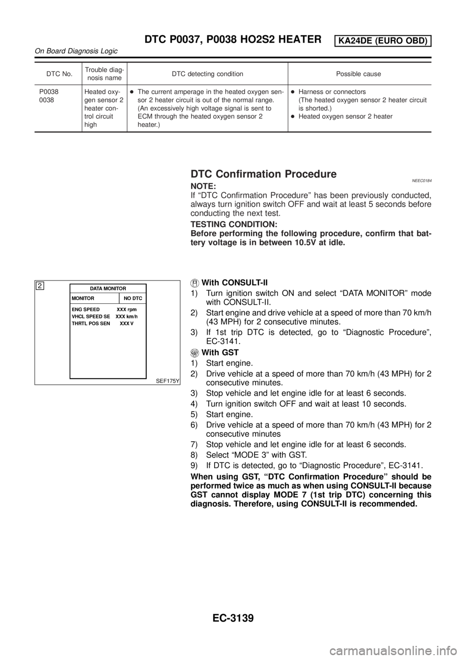
With CONSULT-II
1) Turn ignition switch ON and select ªDATA MONITORº mode
with CONSULT-II.
2) Start engine and drive vehicle at a speed of more than 70 km/h
(43 MPH) for 2 consecutive minutes.
3) If 1st trip DTC is detected, go to ªDiagnostic Procedureº,
EC-3141.
With GST
1) Start engine.
2) Drive vehicle at a speed of more than 70 km/h (43 MPH) for 2
consecutive minutes.
3) Stop vehicle and let engine idle for at least 6 seconds.
4) Turn ignition switch OFF and wait at least 10 seconds.
5) Start engine.
6) Drive vehicle at a speed of more than 70 km/h (43 MPH) for 2
consecutive minutes
7) Stop vehicle and let engine idle for at least 6 seconds.
8) Select ªMODE 3º with GST.
9) If DTC is detected, go to ªDiagnostic Procedureº, EC-3141.
When using GST, ªDTC Confirmation Procedureº should be
performed twice as much as when using CONSULT-II because
GST cannot display MODE 7 (1st trip DTC) concerning this
diagnosis. Therefore, using CONSULT-II is recommended.
DTC P0037, P0038 HO2S2 HEATERKA24DE (EURO OBD)
On Board Diagnosis Logic
EC-3139
Page 169 of 1306
DTC No. Malfunction is detected when ... Check Items (Possible Cause)
P0101
0101B) A low voltage from the sensor is sent to ECM* under
heavy load driving condition.+Harness or connectors
(The sensor circuit is open or shorted.)
+Intake air leaks
+Mass air flow sensor
*: When this malfunction is detected, the ECM enters fail-safe mode and the MI lights up.
FAIL-SAFE MODENEEC0053S01
Detected items Engine operating condition in fail-safe mode
Mass air flow sensor circuitEngine speed will not rise more than 2,400 rpm due to the fuel
cut.
DTC Confirmation ProcedureNEEC0054CAUTION:
Always drive vehicle at a safe speed.
NOTE:
If ªDTC Confirmation Procedureº has been previously conducted,
always turn ignition switch OFF and wait at least 5 seconds before
conducting the next test.
SEF174Y
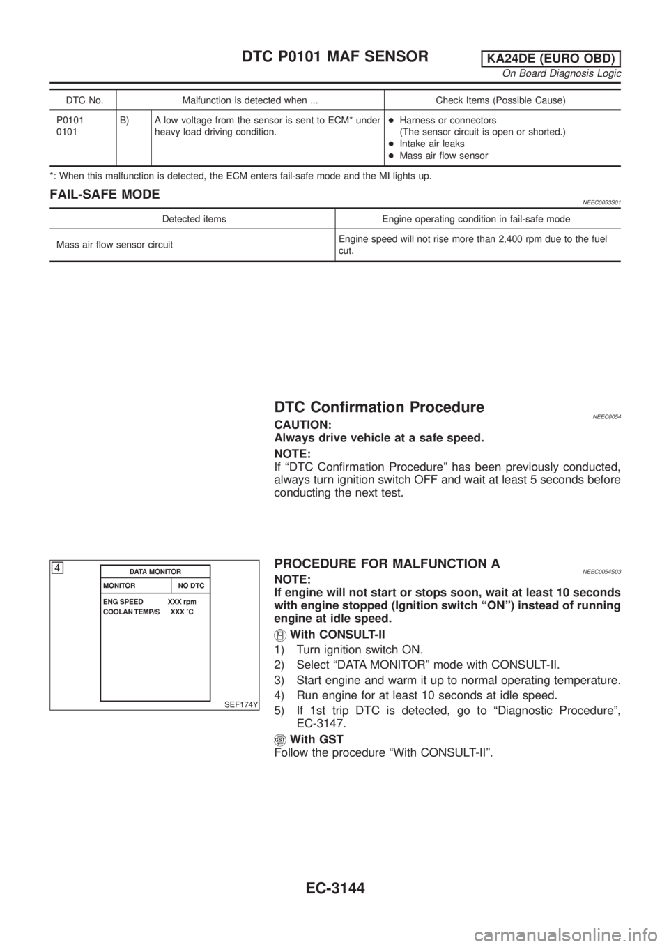
PROCEDURE FOR MALFUNCTION ANEEC0054S03NOTE:
If engine will not start or stops soon, wait at least 10 seconds
with engine stopped (Ignition switch ªONº) instead of running
engine at idle speed.
With CONSULT-II
1) Turn ignition switch ON.
2) Select ªDATA MONITORº mode with CONSULT-II.
3) Start engine and warm it up to normal operating temperature.
4) Run engine for at least 10 seconds at idle speed.
5) If 1st trip DTC is detected, go to ªDiagnostic Procedureº,
EC-3147.
With GST
Follow the procedure ªWith CONSULT-IIº.
DTC P0101 MAF SENSORKA24DE (EURO OBD)
On Board Diagnosis Logic
EC-3144
Page 202 of 1306
7 DETECT MALFUNCTIONING PART
Check harness for open or short between ECM and throttle position sensor.
©Repair open circuit or short to power in harness or connectors.
8 CHECK INPUT SIGNAL CIRCUIT
1. Disconnect ECM harness connector.
2. Check harness continuity between ECM terminal 23 and terminal 2.
Refer to the Wiring Diagram.
Continuity should exist.
3. Also check harness for short to ground and short to power.
OK or NG
OK (With CONSULT-II)©GO TO 9.
OK (Without CONSULT-
II)©GO TO 10.
NG©Repair open circuit or short to ground or short to power in harness or connectors.
9 CHECK THROTTLE POSITION SENSOR
With CONSULT-II
1. Reconnect all harness connectors disconnected.
2. Start engine and warm it up to normal operating temperature.
3. Stop engine and turn ignition switch ON.
4. Select ªDATA MONITORº mode with CONSULT-II.
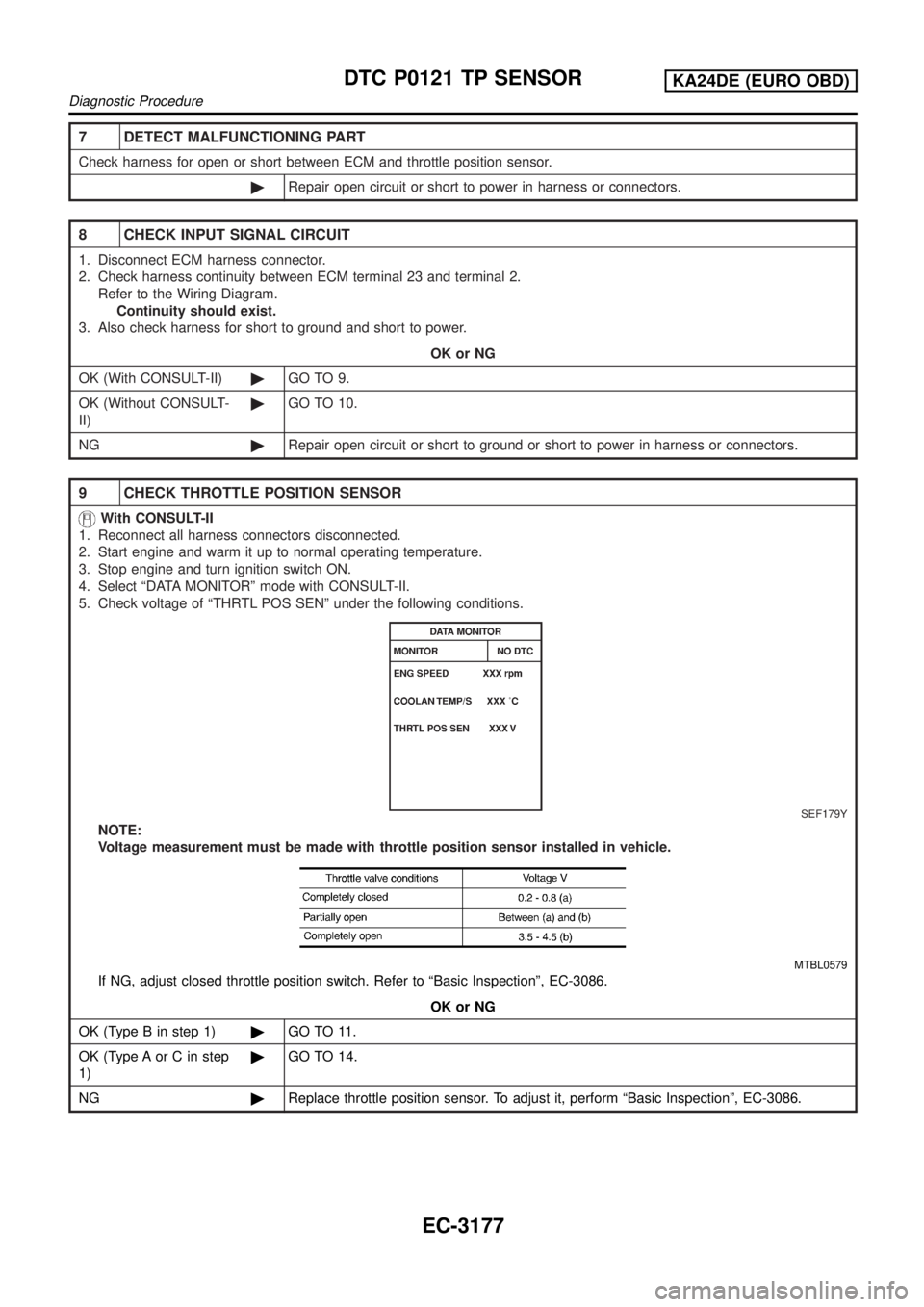
5. Check voltage of ªTHRTL POS SENº under the following conditions.
SEF179Y
NOTE:
Voltage measurement must be made with throttle position sensor installed in vehicle.
MTBL0579
If NG, adjust closed throttle position switch. Refer to ªBasic Inspectionº, EC-3086.
OK or NG
OK (Type B in step 1)©GO TO 11.
OK (Type A or C in step
1)©GO TO 14.
NG©Replace throttle position sensor. To adjust it, perform ªBasic Inspectionº, EC-3086.
DTC P0121 TP SENSORKA24DE (EURO OBD)
Diagnostic Procedure
EC-3177
Page 203 of 1306

10 CHECK THROTTLE POSITION SENSOR
Without CONSULT-II
1. Reconnect all harness connectors disconnected.
2. Start engine and warm it up to normal operating temperature.
3. Stop engine and turn ignition switch ON.
4. Check voltage between ECM terminal 23 (Throttle position sensor signal) and ground under the following conditions.
SEF767W
NOTE:
Voltage measurement must be made with throttle position sensor installed in vehicle.
MTBL0579
If NG, adjust closed throttle position switch. Refer to ªBasic Inspectionº, EC-3086.
OK or NG
OK (Type B in step 1)©GO TO 11.
OK (Type A or C in step
1)©GO TO 14.
NG©Replace throttle position sensor. To adjust it, perform ªBasic Inspectionº, EC-3086.
DTC P0121 TP SENSORKA24DE (EURO OBD)
Diagnostic Procedure
EC-3178
Page 213 of 1306
6 CHECK THROTTLE POSITION SENSOR
With CONSULT-II
1. Reconnect all harness connectors disconnected.
2. Start engine and warm it up to normal operating temperature.
3. Stop engine and turn ignition switch ON.
4. Select ªDATA MONITORº mode with CONSULT-II.
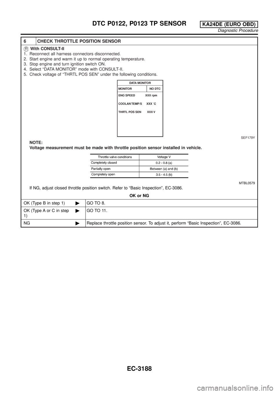
5. Check voltage of ªTHRTL POS SENº under the following conditions.
SEF179Y
NOTE:
Voltage measurement must be made with throttle position sensor installed in vehicle.
MTBL0579
If NG, adjust closed throttle position switch. Refer to ªBasic Inspectionº, EC-3086.
OK or NG
OK (Type B in step 1)©GO TO 8.
OK (Type A or C in step
1)©GO TO 11.
NG©Replace throttle position sensor. To adjust it, perform ªBasic Inspectionº, EC-3086.
DTC P0122, P0123 TP SENSORKA24DE (EURO OBD)
Diagnostic Procedure
EC-3188