2001 NISSAN PICK-UP alternator
[x] Cancel search: alternatorPage 129 of 1306
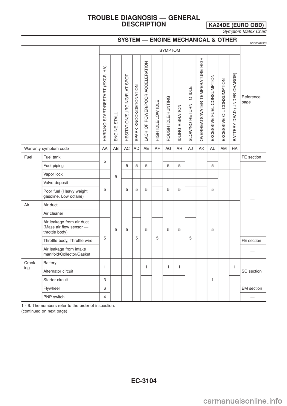
SYSTEM Ð ENGINE MECHANICAL & OTHERNEEC0041S03
SYMPTOM
Reference
page
HARD/NO START/RESTART (EXCP. HA)
ENGINE STALL
HESITATION/SURGING/FLAT SPOT
SPARK KNOCK/DETONATION
LACK OF POWER/POOR ACCELERATION
HIGH IDLE/LOW IDLE
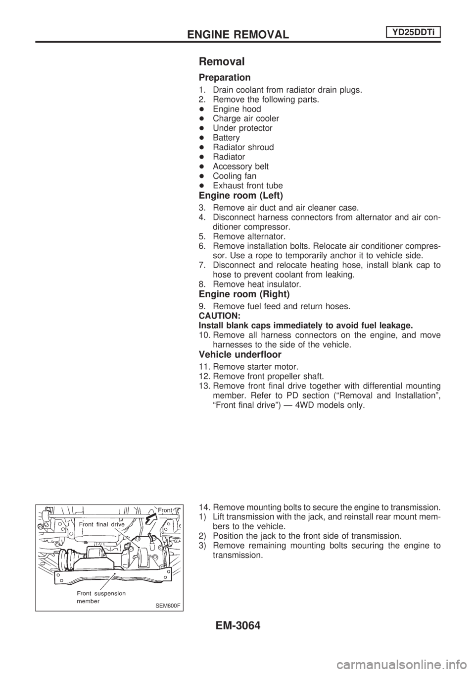
ROUGH IDLE/HUNTING
IDLING VIBRATION
SLOW/NO RETURN TO IDLE
OVERHEATS/WATER TEMPERATURE HIGH
EXCESSIVE FUEL CONSUMPTION
EXCESSIVE OIL CONSUMPTION
BATTERY DEAD (UNDER CHARGE)
Warranty symptom code AA AB AC AD AE AF AG AH AJ AK AL AM HA
Fuel Fuel tank
5
5FE section
Fuel piping 5 5 5 5 5 5
Ð Vapor lock
Valve deposit
555555 5
Poor fuel (Heavy weight
gasoline, Low octane)
Air Air duct
55 5 55 5 Air cleaner
Air leakage from air duct
(Mass air flow sensor Ð
throttle body)
555 5
Throttle body, Throttle wireFE section
Air leakage from intake
manifold/Collector/GasketÐ
Crank-
ingBattery
111 1 11
11
SC section Alternator circuit
Starter circuit 3
Flywheel 6EM section
PNP switch 4Ð
1 - 6: The numbers refer to the order of inspection.
(continued on next page)
TROUBLE DIAGNOSIS Ð GENERAL
DESCRIPTION
KA24DE (EURO OBD)
Symptom Matrix Chart
EC-3104
Page 565 of 1306
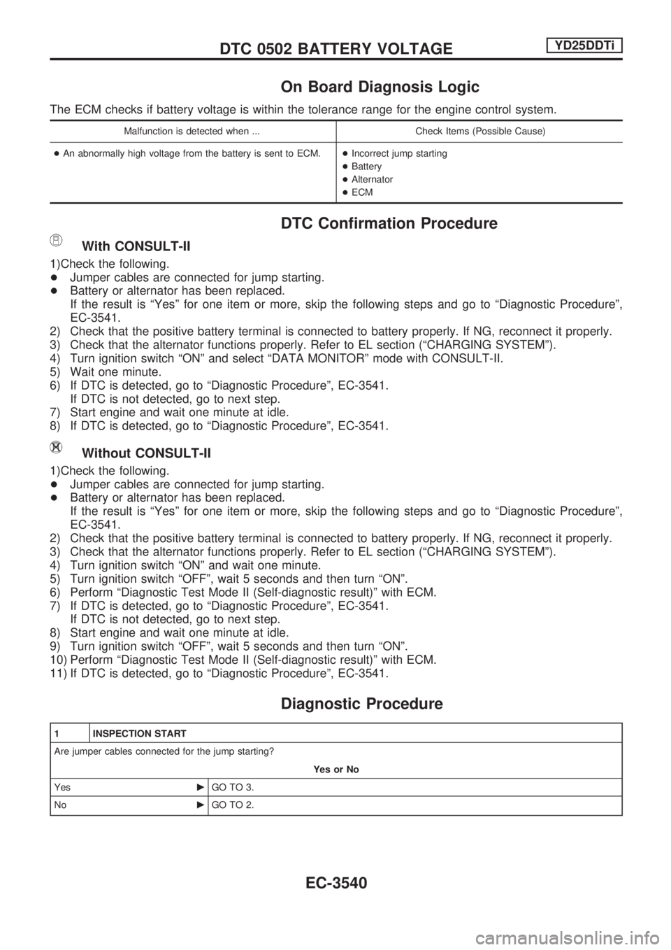
On Board Diagnosis Logic
The ECM checks if battery voltage is within the tolerance range for the engine control system.
Malfunction is detected when ... Check Items (Possible Cause)
+An abnormally high voltage from the battery is sent to ECM.+Incorrect jump starting
+Battery
+Alternator
+ECM
DTC Confirmation Procedure
With CONSULT-II
1)Check the following.
+Jumper cables are connected for jump starting.
+Battery or alternator has been replaced.
If the result is ªYesº for one item or more, skip the following steps and go to ªDiagnostic Procedureº,
EC-3541.
2) Check that the positive battery terminal is connected to battery properly. If NG, reconnect it properly.
3) Check that the alternator functions properly. Refer to EL section (ªCHARGING SYSTEMº).
4) Turn ignition switch ªONº and select ªDATA MONITORº mode with CONSULT-II.
5) Wait one minute.
6) If DTC is detected, go to ªDiagnostic Procedureº, EC-3541.
If DTC is not detected, go to next step.
7) Start engine and wait one minute at idle.
8) If DTC is detected, go to ªDiagnostic Procedureº, EC-3541.
Without CONSULT-II
1)Check the following.
+Jumper cables are connected for jump starting.
+Battery or alternator has been replaced.
If the result is ªYesº for one item or more, skip the following steps and go to ªDiagnostic Procedureº,
EC-3541.
2) Check that the positive battery terminal is connected to battery properly. If NG, reconnect it properly.
3) Check that the alternator functions properly. Refer to EL section (ªCHARGING SYSTEMº).
4) Turn ignition switch ªONº and wait one minute.
5) Turn ignition switch ªOFFº, wait 5 seconds and then turn ªONº.
6) Perform ªDiagnostic Test Mode II (Self-diagnostic result)º with ECM.
7) If DTC is detected, go to ªDiagnostic Procedureº, EC-3541.
If DTC is not detected, go to next step.
8) Start engine and wait one minute at idle.
9) Turn ignition switch ªOFFº, wait 5 seconds and then turn ªONº.
10) Perform ªDiagnostic Test Mode II (Self-diagnostic result)º with ECM.
11) If DTC is detected, go to ªDiagnostic Procedureº, EC-3541.
Diagnostic Procedure
1 INSPECTION START
Are jumper cables connected for the jump starting?
Yes or No
YescGO TO 3.
NocGO TO 2.
DTC 0502 BATTERY VOLTAGEYD25DDTi
EC-3540
Page 566 of 1306
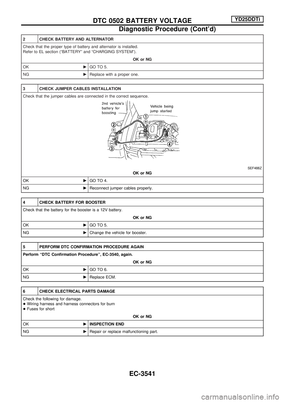
2 CHECK BATTERY AND ALTERNATOR
Check that the proper type of battery and alternator is installed.
Refer to EL section (ªBATTERYº and ªCHARGING SYSTEMº).
OK or NG
OKcGO TO 5.
NGcReplace with a proper one.
3 CHECK JUMPER CABLES INSTALLATION
Check that the jumper cables are connected in the correct sequence.
SEF488Z
OK or NG
OKcGO TO 4.
NGcReconnect jumper cables properly.
4 CHECK BATTERY FOR BOOSTER
Check that the battery for the booster is a 12V battery.
OK or NG
OKcGO TO 5.
NGcChange the vehicle for booster.
5 PERFORM DTC CONFIRMATION PROCEDURE AGAIN
Perform ªDTC Confirmation Procedureº, EC-3540, again.
OK or NG
OKcGO TO 6.
NGcReplace ECM.
6 CHECK ELECTRICAL PARTS DAMAGE
Check the following for damage.
+Wiring harness and harness connectors for burn
+Fuses for short
OK or NG
OKcINSPECTION END
NGcRepair or replace malfunctioning part.
DTC 0502 BATTERY VOLTAGEYD25DDTi
Diagnostic Procedure (Cont'd)
EC-3541
Page 677 of 1306

METER AND GAUGES....................................... 3056
System Description .......................................... 3056
Combination Meter/With Tachometer .............. 3057
Combination Meter/Without Tachometer ......... 3058
Schematic/With Tachometer ............................ 3059
Schematic/Without Tachometer ....................... 3060
Construction ..................................................... 3061
Wiring Diagram - METER -/Gasoline Engine
with Tachometer .............................................. 3062
Wiring Diagram - METER -/Gasoline Engine
without Tachometer ......................................... 3064
Wiring Diagram - METER -/LHD Diesel Engine
Models with Tachometer.................................. 3065
Wiring Diagram - METER -/RHD Diesel
Engine Models with Tachometer ..................... 3067
Wiring Diagram - METER -/Diesel Engine
without Tachometer ......................................... 3069
Meter/Gauge Operation and Odo/Trip Meter
Segment Check in Diagnosis Mode ................ 3070
Trouble Diagnoses/With Tachometer .............. 3071
Trouble Diagnoses/Without Tachometer ......... 3076
WARNING LAMPS.............................................. 3081
Schematic/With Tachometer ............................ 3081
Schematic/Without Tachometer ....................... 3082
Wiring Diagram - WARN -/Gasoline Engine
with Tachometer .............................................. 3083
Wiring Diagram - WARN -/Gasoline Engine
without Tachometer ......................................... 3087
Wiring Diagram - WARN -/Diesel Engine with
Tachometer ...................................................... 3091
Wiring Diagram - WARN -/Diesel Engine
without Tachometer ......................................... 3095
A/T INDICATOR................................................... 3100
Wiring Diagram - AT/IND -/RHD Models ......... 3100
Wiring Diagram - CHIME -/LHD Models.......... 3101
Wiring Diagram - CHIME -/RHD Models ......... 3102
FRONT WIPER AND WASHER.......................... 3103
Wiring Diagram - WIPER -/Without Intermittent
for Floor-shift .................................................... 3103
Wiring Diagram - WIPER -/Without Intermittent
for RHD Column-shift Models .......................... 3106
HEADLAMP WASHER........................................ 3108
Wiring Diagram - HLC - ................................... 3108
HORN................................................................... 3109
Wiring Diagram - HORN -................................ 3109
CIGARETTE LIGHTER........................................ 3110
Wiring Diagram - CIGAR - ............................... 3110
CLOCK................................................................. 3111
Wiring Diagram - CLOCK - .............................. 3111
REAR WINDOW DEFOGGER AND MIRROR
DEFOGGER......................................................... 3112
Wiring Diagram - DEF - ................................... 3112
AUDIO.................................................................. 3113
Wiring Diagram - AUDIO -/LHD Models .......... 3113Wiring Diagram - AUDIO -/RHD Models ......... 3114
AUDIO ANTENNA............................................... 3115
Power Antenna/Wiring Diagram - P/ANT - ...... 3115
POWER DOOR MIRROR.................................... 3116
Wiring Diagram - MIRROR -/LHD Models....... 3116
Wiring Diagram - MIRROR -/RHD Models ...... 3117
HEATED SEAT.................................................... 3118
Wiring Diagram - H/SEAT - ............................. 3118
POWER WINDOW............................................... 3120
Schematic/Without Interruption Detection
Function ........................................................... 3120
Schematic/With Interruption Detection
Function ........................................................... 3121
Wiring Diagram - WINDOW -/Without
Interruption Detection Function........................ 3122
Wiring Diagram - WINDOW -/With Interruption
Detection Function ........................................... 3126
Trouble Diagnoses/Without Interruption
Detection Function ........................................... 3130
Trouble Diagnoses/With Interruption Detection
Function ........................................................... 3131
POWER DOOR LOCK......................................... 3133
Wiring Diagram - D/LOCK - ............................. 3133
MULTI-REMOTE CONTROL SYSTEM............... 3135
System Description .......................................... 3135
MULTI-REMOTE CONTROL SYSTEM............... 3136
Wiring Diagram - MULTI - ............................... 3136
Trouble Diagnoses ........................................... 3137
ID Code Entry Procedure ................................ 3139
Remote Controller Battery Replacement ......... 3140
THEFT WARNING SYSTEM............................... 3141
Wiring Diagram - PRWIRE - ............................ 3141
NATS (Nissan Anti-Theft System).................... 3142
Component Parts and Harness Connector
Location............................................................ 3142
System Description .......................................... 3143
System Composition ........................................ 3144
Wiring Diagram - NATS -/LHD Models............ 3145
Wiring Diagram - NATS -/RHD Diesel Engine
Models.............................................................. 3146
CONSULT-II ..................................................... 3147
Trouble Diagnoses ........................................... 3149
How to Replace NATS IMMU .......................... 3160
LOCATION OF ELECTRICAL UNITS................. 3161
Engine Compartment ....................................... 3161
Passenger Compartment ................................. 3162
HARNESS LAYOUT............................................ 3164
Main Harness ................................................... 3164
Engine Room Harness..................................... 3174
Engine Control Harness/KA engine ................. 3182
Engine Control Harness................................... 3184
Engine Harness ............................................... 3185
Alternator Harness ........................................... 3187
Instrument Harness.......................................... 3189
EL-3002
Page 697 of 1306
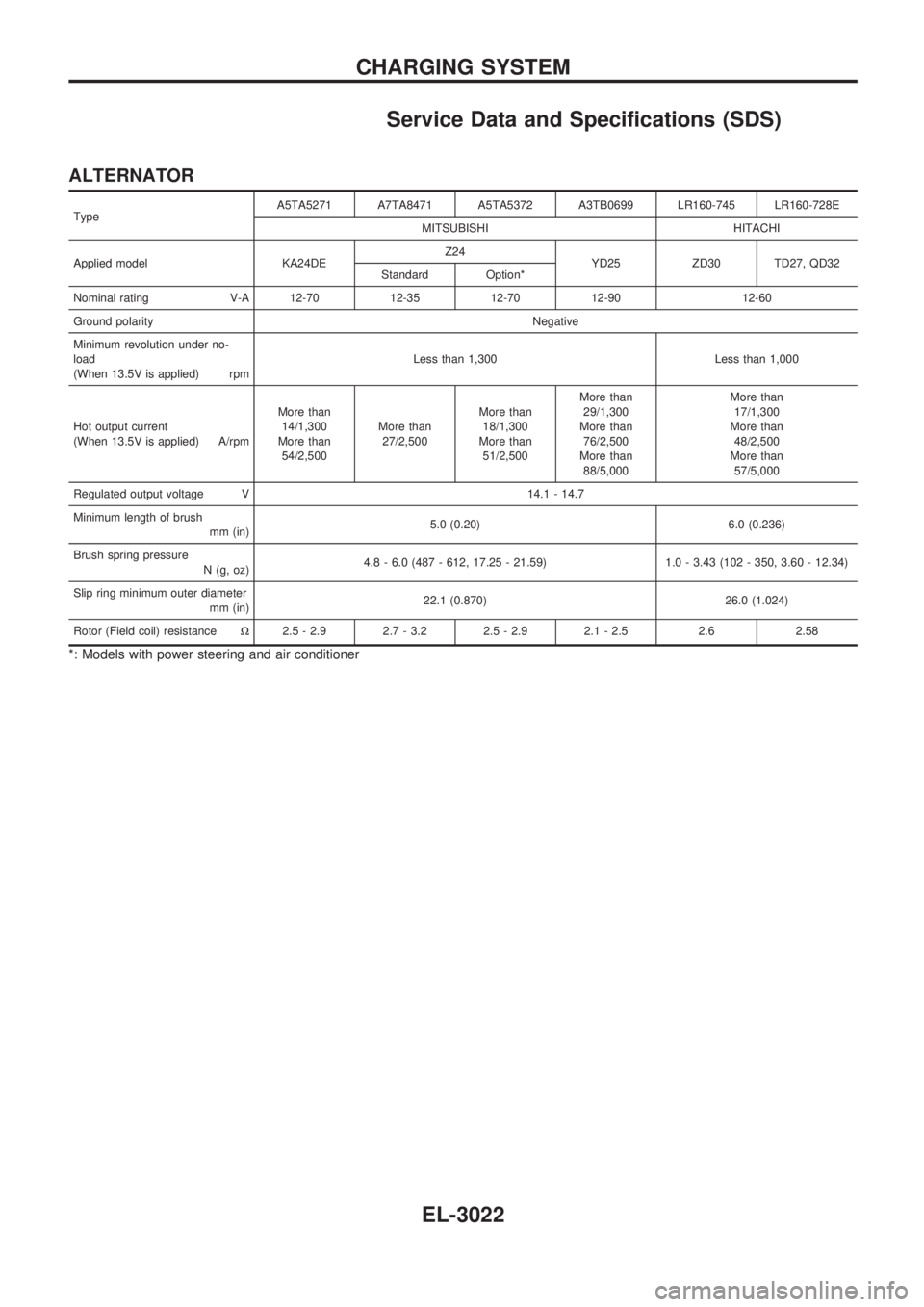
Service Data and Specifications (SDS)
ALTERNATOR
TypeA5TA5271 A7TA8471 A5TA5372 A3TB0699 LR160-745 LR160-728E
MITSUBISHI HITACHI
Applied model KA24DEZ24
YD25 ZD30 TD27, QD32
Standard Option*
Nominal rating V-A 12-70 12-35 12-70 12-90 12-60
Ground polarityNegative
Minimum revolution under no-
load
(When 13.5V is applied) rpmLess than 1,300 Less than 1,000
Hot output current
(When 13.5V is applied) A/rpmMore than
14/1,300
More than
54/2,500More than
27/2,500More than
18/1,300
More than
51/2,500More than
29/1,300
More than
76/2,500
More than
88/5,000More than
17/1,300
More than
48/2,500
More than
57/5,000
Regulated output voltage V 14.1 - 14.7
Minimum length of brush
mm (in)5.0 (0.20) 6.0 (0.236)
Brush spring pressure
N (g, oz)4.8 - 6.0 (487 - 612, 17.25 - 21.59) 1.0 - 3.43 (102 - 350, 3.60 - 12.34)
Slip ring minimum outer diameter
mm (in)22.1 (0.870) 26.0 (1.024)
Rotor (Field coil) resistanceW2.5 - 2.9 2.7 - 3.2 2.5 - 2.9 2.1 - 2.5 2.6 2.58
*: Models with power steering and air conditioner
CHARGING SYSTEM
EL-3022
Page 862 of 1306

Alternator Harness
HEL808B
HARNESS LAYOUT
EL-3187
Page 863 of 1306

YD ENGINE
HEL882B
HARNESS LAYOUT
Alternator Harness (Cont'd)
EL-3188
Page 941 of 1306
Removal
Preparation
1. Drain coolant from radiator drain plugs.
2. Remove the following parts.
+Engine hood
+Charge air cooler
+Under protector
+Battery
+Radiator shroud
+Radiator
+Accessory belt
+Cooling fan
+Exhaust front tube
Engine room (Left)
3. Remove air duct and air cleaner case.
4. Disconnect harness connectors from alternator and air con-
ditioner compressor.
5. Remove alternator.
6. Remove installation bolts. Relocate air conditioner compres-
sor. Use a rope to temporarily anchor it to vehicle side.
7. Disconnect and relocate heating hose, install blank cap to
hose to prevent coolant from leaking.
8. Remove heat insulator.
Engine room (Right)
9. Remove fuel feed and return hoses.
CAUTION:
Install blank caps immediately to avoid fuel leakage.
10. Remove all harness connectors on the engine, and move
harnesses to the side of the vehicle.
Vehicle underfloor
11. Remove starter motor.
12. Remove front propeller shaft.
13. Remove front final drive together with differential mounting
member. Refer to PD section (ªRemoval and Installationº,
ªFront final driveº) Ð 4WD models only.
14. Remove mounting bolts to secure the engine to transmission.
1) Lift transmission with the jack, and reinstall rear mount mem-
bers to the vehicle.
2) Position the jack to the front side of transmission.
3) Remove remaining mounting bolts securing the engine to
transmission.
SEM600F
ENGINE REMOVALYD25DDTi
EM-3064