2001 NISSAN PATROL air condition
[x] Cancel search: air conditionPage 1 of 273
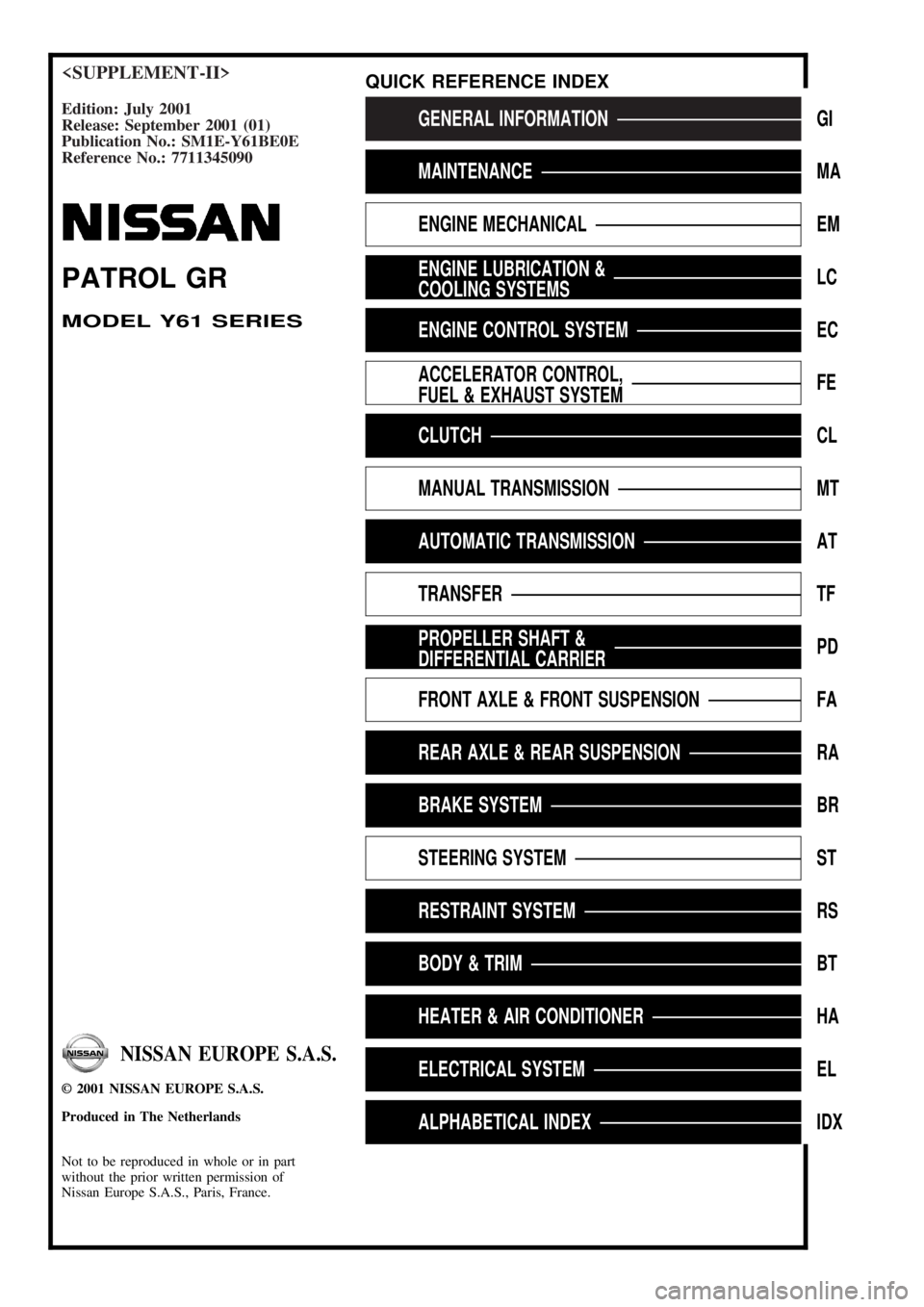
Edition: July 2001
Release: September 2001 (01)
Publication No.: SM1E-Y61BE0E
Reference No.: 7711345090GENERAL INFORMATIONGI
MAINTENANCEMA
ENGINE MECHANICALEM
ENGINE LUBRICATION &
COOLING SYSTEMSLC
ENGINE CONTROL SYSTEMEC
ACCELERATOR CONTROL,
FUEL & EXHAUST SYSTEMFE
CLUTCHCL
MANUAL TRANSMISSIONMT
AUTOMATIC TRANSMISSIONAT
TRANSFERTF
PROPELLER SHAFT &
DIFFERENTIAL CARRIERPD
FRONT AXLE & FRONT SUSPENSIONFA
REAR AXLE & REAR SUSPENSIONRA
BRAKE SYSTEMBR
STEERING SYSTEMST
RESTRAINT SYSTEMRS
BODY & TRIMBT
HEATER & AIR CONDITIONERHA
ELECTRICAL SYSTEMEL
ALPHABETICAL INDEXIDX
PATROL GR
MODEL Y61 SERIES
NISSAN EUROPE S.A.S.
2001 NISSAN EUROPE S.A.S.
Produced in The Netherlands
Not to be reproduced in whole or in part
without the prior written permission of
Nissan Europe S.A.S., Paris, France.
QUICK REFERENCE INDEX
Page 38 of 273
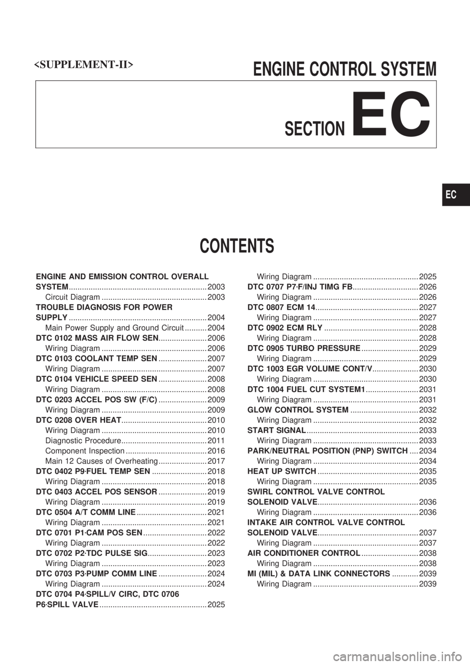
ENGINE CONTROL SYSTEM
SECTION
EC
CONTENTS
ENGINE AND EMISSION CONTROL OVERALL
SYSTEM............................................................... 2003
Circuit Diagram ................................................ 2003
TROUBLE DIAGNOSIS FOR POWER
SUPPLY............................................................... 2004
Main Power Supply and Ground Circuit .......... 2004
DTC 0102 MASS AIR FLOW SEN...................... 2006
Wiring Diagram ................................................ 2006
DTC 0103 COOLANT TEMP SEN...................... 2007
Wiring Diagram ................................................ 2007
DTC 0104 VEHICLE SPEED SEN...................... 2008
Wiring Diagram ................................................ 2008
DTC 0203 ACCEL POS SW (F/C)...................... 2009
Wiring Diagram ................................................ 2009
DTC 0208 OVER HEAT....................................... 2010
Wiring Diagram ................................................ 2010
Diagnostic Procedure....................................... 2011
Component Inspection ..................................... 2016
Main 12 Causes of Overheating ...................... 2017
DTC 0402 P9zFUEL TEMP SEN......................... 2018
Wiring Diagram ................................................ 2018
DTC 0403 ACCEL POS SENSOR...................... 2019
Wiring Diagram ................................................ 2019
DTC 0504 A/T COMM LINE................................ 2021
Wiring Diagram ................................................ 2021
DTC 0701 P1zCAM POS SEN............................. 2022
Wiring Diagram ................................................ 2022
DTC 0702 P2zTDC PULSE SIG........................... 2023
Wiring Diagram ................................................ 2023
DTC 0703 P3zPUMP COMM LINE...................... 2024
Wiring Diagram ................................................ 2024
DTC 0704 P4zSPILL/V CIRC, DTC 0706
P6zSPILL VALVE................................................. 2025Wiring Diagram ................................................ 2025
DTC 0707 P7zF/INJ TIMG FB.............................. 2026
Wiring Diagram ................................................ 2026
DTC 0807 ECM 14............................................... 2027
Wiring Diagram ................................................ 2027
DTC 0902 ECM RLY........................................... 2028
Wiring Diagram ................................................ 2028
DTC 0905 TURBO PRESSURE.......................... 2029
Wiring Diagram ................................................ 2029
DTC 1003 EGR VOLUME CONT/V..................... 2030
Wiring Diagram ................................................ 2030
DTC 1004 FUEL CUT SYSTEM1........................ 2031
Wiring Diagram ................................................ 2031
GLOW CONTROL SYSTEM............................... 2032
Wiring Diagram ................................................ 2032
START SIGNAL................................................... 2033
Wiring Diagram ................................................ 2033
PARK/NEUTRAL POSITION (PNP) SWITCH.... 2034
Wiring Diagram ................................................ 2034
HEAT UP SWITCH.............................................. 2035
Wiring Diagram ................................................ 2035
SWIRL CONTROL VALVE CONTROL
SOLENOID VALVE.............................................. 2036
Wiring Diagram ................................................ 2036
INTAKE AIR CONTROL VALVE CONTROL
SOLENOID VALVE.............................................. 2037
Wiring Diagram ................................................ 2037
AIR CONDITIONER CONTROL.......................... 2038
Wiring Diagram ................................................ 2038
MI (MIL) & DATA LINK CONNECTORS............ 2039
Wiring Diagram ................................................ 2039
EC
Page 75 of 273
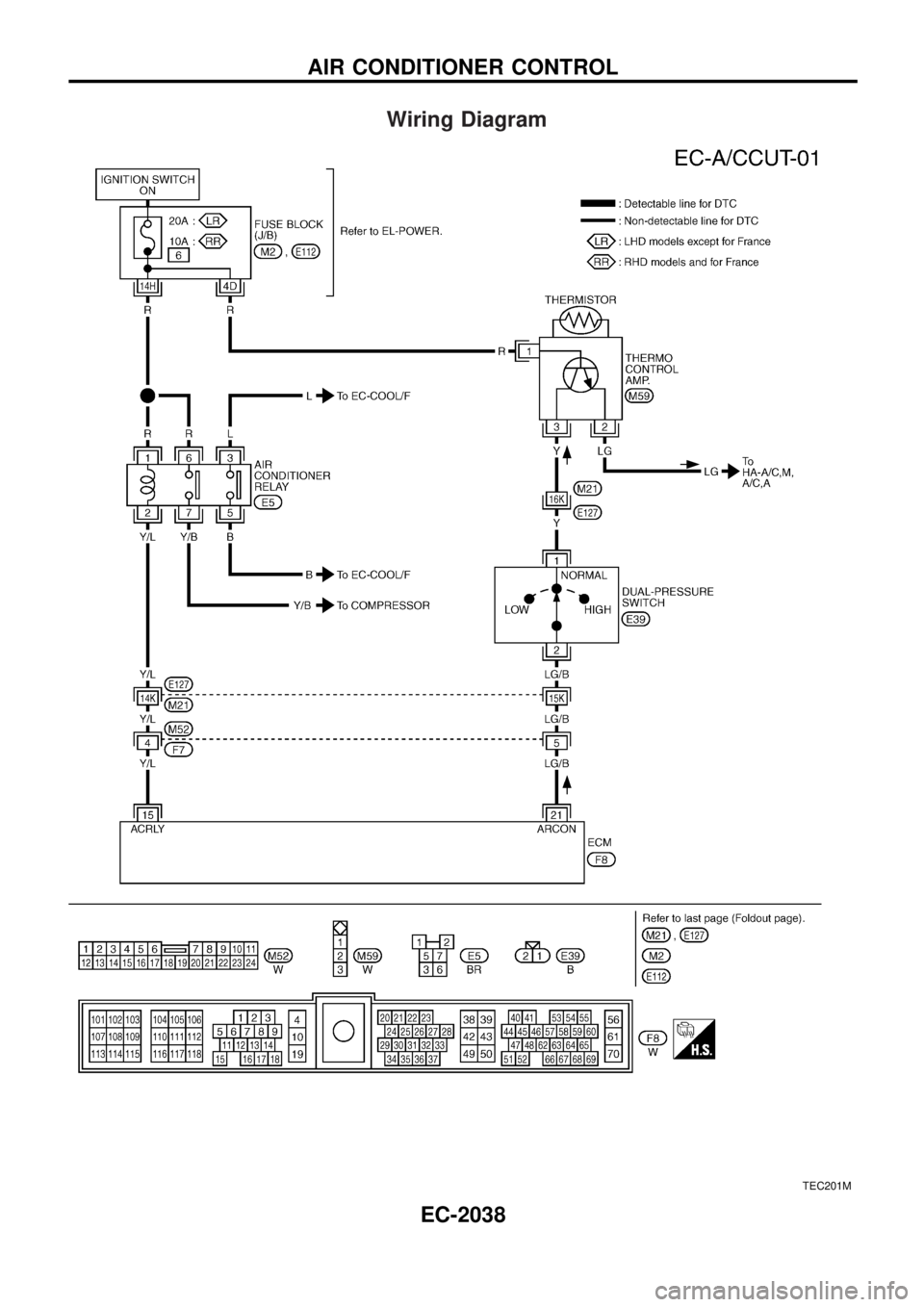
Wiring Diagram
TEC201M
AIR CONDITIONER CONTROL
EC-2038
Page 209 of 273
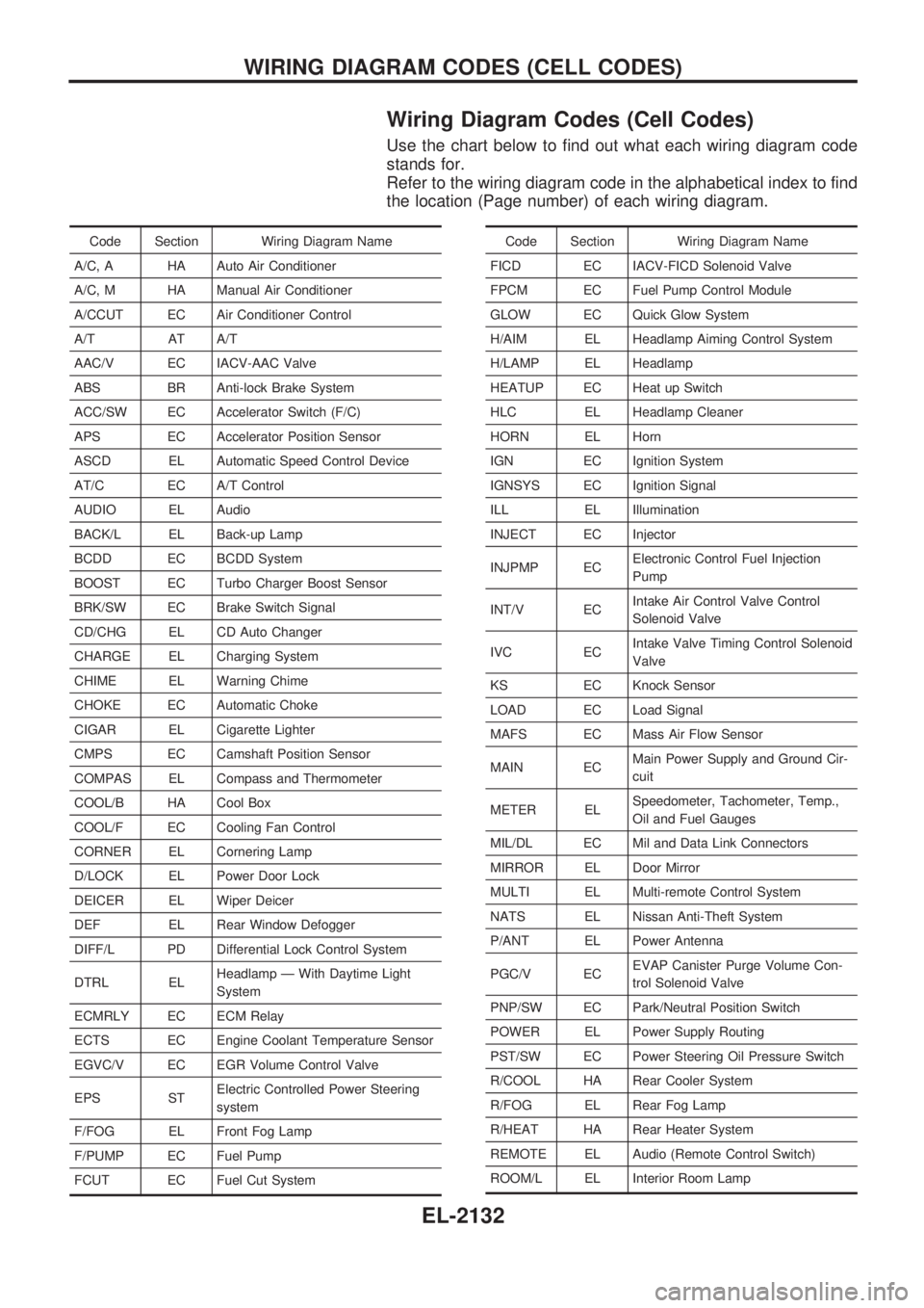
Wiring Diagram Codes (Cell Codes)
Use the chart below to find out what each wiring diagram code
stands for.
Refer to the wiring diagram code in the alphabetical index to find
the location (Page number) of each wiring diagram.
Code Section Wiring Diagram Name
A/C, A HA Auto Air Conditioner
A/C, M HA Manual Air Conditioner
A/CCUT EC Air Conditioner Control
A/T AT A/T
AAC/V EC IACV-AAC Valve
ABS BR Anti-lock Brake System
ACC/SW EC Accelerator Switch (F/C)
APS EC Accelerator Position Sensor
ASCD EL Automatic Speed Control Device
AT/C EC A/T Control
AUDIO EL Audio
BACK/L EL Back-up Lamp
BCDD EC BCDD System
BOOST EC Turbo Charger Boost Sensor
BRK/SW EC Brake Switch Signal
CD/CHG EL CD Auto Changer
CHARGE EL Charging System
CHIME EL Warning Chime
CHOKE EC Automatic Choke
CIGAR EL Cigarette Lighter
CMPS EC Camshaft Position Sensor
COMPAS EL Compass and Thermometer
COOL/B HA Cool Box
COOL/F EC Cooling Fan Control
CORNER EL Cornering Lamp
D/LOCK EL Power Door Lock
DEICER EL Wiper Deicer
DEF EL Rear Window Defogger
DIFF/L PD Differential Lock Control System
DTRL ELHeadlamp Ð With Daytime Light
System
ECMRLY EC ECM Relay
ECTS EC Engine Coolant Temperature Sensor
EGVC/V EC EGR Volume Control Valve
EPS STElectric Controlled Power Steering
system
F/FOG EL Front Fog Lamp
F/PUMP EC Fuel Pump
FCUT EC Fuel Cut SystemCode Section Wiring Diagram Name
FICD EC IACV-FICD Solenoid Valve
FPCM EC Fuel Pump Control Module
GLOW EC Quick Glow System
H/AIM EL Headlamp Aiming Control System
H/LAMP EL Headlamp
HEATUP EC Heat up Switch
HLC EL Headlamp Cleaner
HORN EL Horn
IGN EC Ignition System
IGNSYS EC Ignition Signal
ILL EL Illumination
INJECT EC Injector
INJPMP ECElectronic Control Fuel Injection
Pump
INT/V ECIntake Air Control Valve Control
Solenoid Valve
IVC ECIntake Valve Timing Control Solenoid
Valve
KS EC Knock Sensor
LOAD EC Load Signal
MAFS EC Mass Air Flow Sensor
MAIN ECMain Power Supply and Ground Cir-
cuit
METER ELSpeedometer, Tachometer, Temp.,
Oil and Fuel Gauges
MIL/DL EC Mil and Data Link Connectors
MIRROR EL Door Mirror
MULTI EL Multi-remote Control System
NATS EL Nissan Anti-Theft System
P/ANT EL Power Antenna
PGC/V ECEVAP Canister Purge Volume Con-
trol Solenoid Valve
PNP/SW EC Park/Neutral Position Switch
POWER EL Power Supply Routing
PST/SW EC Power Steering Oil Pressure Switch
R/COOL HA Rear Cooler System
R/FOG EL Rear Fog Lamp
R/HEAT HA Rear Heater System
REMOTE EL Audio (Remote Control Switch)
ROOM/L EL Interior Room Lamp
WIRING DIAGRAM CODES (CELL CODES)
EL-2132
Page 220 of 273
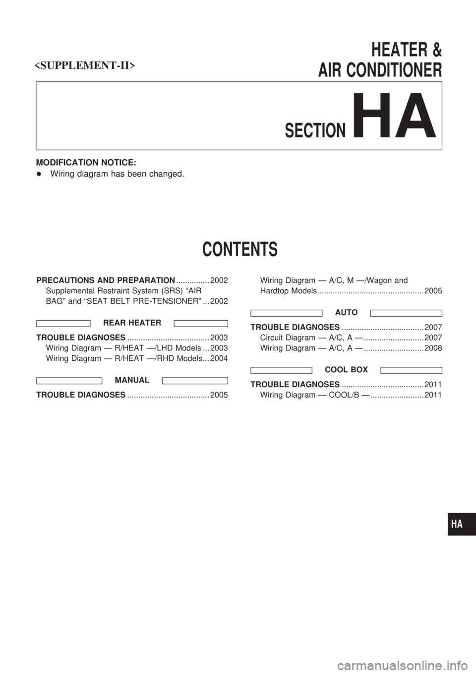
HEATER &
AIR CONDITIONER
SECTION
HA
MODIFICATION NOTICE:
+Wiring diagram has been changed.
CONTENTS
PRECAUTIONS AND PREPARATION............... 2002
Supplemental Restraint System (SRS) ªAIR
BAGº and ªSEAT BELT PRE-TENSIONERº ... 2002
REAR HEATER
TROUBLE DIAGNOSES..................................... 2003
Wiring Diagram Ð R/HEAT Ð/LHD Models ... 2003
Wiring Diagram Ð R/HEAT Ð/RHD Models... 2004
MANUAL
TROUBLE DIAGNOSES..................................... 2005Wiring Diagram Ð A/C, M Ð/Wagon and
Hardtop Models................................................ 2005
AUTO
TROUBLE DIAGNOSES..................................... 2007
Circuit Diagram Ð A/C, A Ð ........................... 2007
Wiring Diagram Ð A/C, A Ð ........................... 2008
COOL BOX
TROUBLE DIAGNOSES..................................... 2011
Wiring Diagram Ð COOL/B Ð ........................ 2011
HA
Page 241 of 273
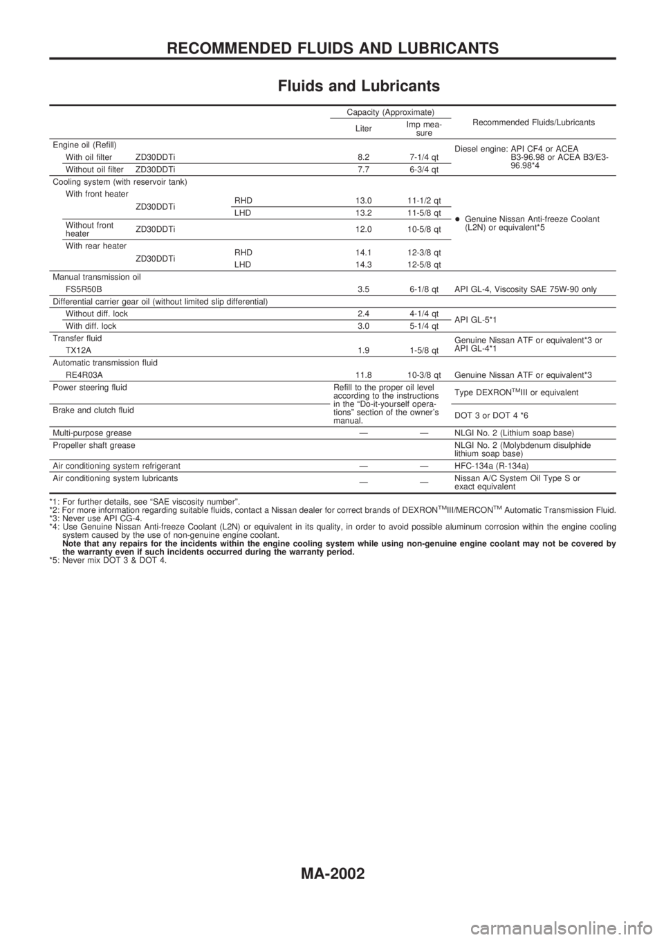
Fluids and Lubricants
Capacity (Approximate)
Recommended Fluids/Lubricants
LiterImp mea-
sure
Engine oil (Refill)
Diesel engine: API CF4 or ACEA
B3-96.98 or ACEA B3/E3-
96.98*4 With oil filter ZD30DDTi 8.2 7-1/4 qt
Without oil filter ZD30DDTi 7.7 6-3/4 qt
Cooling system (with reservoir tank)
+Genuine Nissan Anti-freeze Coolant
(L2N) or equivalent*5 With front heater
ZD30DDTiRHD 13.0 11-1/2 qt
LHD 13.2 11-5/8 qt
Without front
heaterZD30DDTi 12.0 10-5/8 qt
With rear heater
ZD30DDTiRHD 14.1 12-3/8 qt
LHD 14.3 12-5/8 qt
Manual transmission oil
FS5R50B 3.5 6-1/8 qt API GL-4, Viscosity SAE 75W-90 only
Differential carrier gear oil (without limited slip differential)
Without diff. lock 2.4 4-1/4 qt
API GL-5*1
With diff. lock 3.0 5-1/4 qt
Transfer fluid
Genuine Nissan ATF or equivalent*3 or
API GL-4*1
TX12A 1.9 1-5/8 qt
Automatic transmission fluid
RE4R03A 11.8 10-3/8 qt Genuine Nissan ATF or equivalent*3
Power steering fluid Refill to the proper oil level
according to the instructions
in the ªDo-it-yourself opera-
tionsº section of the owner's
manual.Type DEXRON
TMIII or equivalent
Brake and clutch fluid
DOT3orDOT4*6
Multi-purpose grease Ð Ð NLGI No. 2 (Lithium soap base)
Propeller shaft greaseNLGI No. 2 (Molybdenum disulphide
lithium soap base)
Air conditioning system refrigerant Ð Ð HFC-134a (R-134a)
Air conditioning system lubricants
ÐÐNissan A/C System Oil Type S or
exact equivalent
*1: For further details, see ªSAE viscosity numberº.
*2: For more information regarding suitable fluids, contact a Nissan dealer for correct brands of DEXRON
TMIII/MERCONTMAutomatic Transmission Fluid.
*3: Never use API CG-4.
*4: Use Genuine Nissan Anti-freeze Coolant (L2N) or equivalent in its quality, in order to avoid possible aluminum corrosion within the engine cooling
system caused by the use of non-genuine engine coolant.
Note that any repairs for the incidents within the engine cooling system while using non-genuine engine coolant may not be covered by
the warranty even if such incidents occurred during the warranty period.
*5: Never mix DOT 3 & DOT 4.
RECOMMENDED FLUIDS AND LUBRICANTS
MA-2002
Page 268 of 273
![NISSAN PATROL 2001 Electronic Repair Manual HOW TO ERASE SELF-DIAGNOSIS RESULTS
With CONSULT-II
+ªSELF-DIAG [CURRENT]º
A current Self-diagnosis result is displayed on the CON-
SULT-II screen in real time. After the malfunction is repaired
com NISSAN PATROL 2001 Electronic Repair Manual HOW TO ERASE SELF-DIAGNOSIS RESULTS
With CONSULT-II
+ªSELF-DIAG [CURRENT]º
A current Self-diagnosis result is displayed on the CON-
SULT-II screen in real time. After the malfunction is repaired
com](/manual-img/5/57366/w960_57366-267.png)
HOW TO ERASE SELF-DIAGNOSIS RESULTS
With CONSULT-II
+ªSELF-DIAG [CURRENT]º
A current Self-diagnosis result is displayed on the CON-
SULT-II screen in real time. After the malfunction is repaired
completely, no malfunction is detected on ªSELF-DIAG
[CURRENT]º.
+ªSELF-DIAG [PAST]º
Return to the ªSELF-DIAG [CURRENT]º CONSULT-II screen
by pushing ªBACKº key of CONSULT-II and select ªSELF-
DIAG [CURRENT]º in ªSELECT DIAG MODEº. Touch
ªERASEº in ªSELF-DIAG [CURRENT]º mode.
NOTE:
If the memory of the malfunction in ªSELF-DIAG [PAST]º is
not erased, the User mode shows the system malfunction by
the operation of the warning lamp even if the malfunction is
repaired completely.
+ªTROUBLE DIAG RECORDº
The memory of ªTROUBLE DIAG RECORDº cannot be
erased.
Without CONSULT-II
After a malfunction is repaired, return Diagnosis mode to User
mode by switching the ignition ªOFFº for at least 1 second, then
back ªONº. At that time, the self-diagnostic result is cleared.
How to Perform Trouble Diagnoses for Quick
and Accurate Repair
A good understanding of the malfunction conditions can make troubleshooting faster and more accurate.
In general, each customer feels differently about a malfunction. It is important to fully understand the symp-
toms or conditions for a customer complaint.
INFORMATION FROM CUSTOMER
WHAT ........ Vehicle model
WHEN ....... Date, Frequencies
WHERE ..... Road conditions
HOW .......... Operating conditions, Symptoms
PRELIMINARY CHECK
Check that the following parts are in good order.
+Battery [Refer to EL section (ªBATTERYº) of Service Manual.]
+Fuse [Refer to EL section (ªFuseº, ªPOWER SUPPLY ROUTINGº) of Service Manual.]
+System component-to-harness connections
SRS701
TROUBLE DIAGNOSES Ð Supplemental Restraint System (SRS)
Trouble Diagnoses Introduction (Cont'd)
RS-2017