2001 NISSAN PATROL Harness
[x] Cancel search: HarnessPage 26 of 273
Service Notice
+When removing or installing various parts, place a cloth or padding onto the vehicle body to prevent
scratches.
+Handle trim, molding, instruments, grille, etc. carefully during removing or installing. Be careful not to soil
or damage them.
+Apply sealing compound where necessary when installing parts.
+When applying sealing compound, be careful that the sealing compound does not protrude from parts.
+When replacing any metal parts (for example body outer panel, members, etc.), be sure to take rust
prevention measures.
Supplemental Restraint System (SRS) ªAIR
BAGº and ªSEAT BELT PRE-TENSIONERº
The Supplemental Restraint System such as ªAIR BAGº and ªSEAT BELT PRE-TENSIONERº used along
with a seat belt, helps to reduce the risk or severity of injury to the driver and front passenger for certain
types of collision. The SRS system composition which is available to NISSAN MODEL Y61 is as follows (The
composition varies according to the destination and optional equipment.):
+For a frontal collision
The Supplemental Restraint System consists of driver air bag module (located in the center of the
steering wheel), front passenger air bag module (located on the instrument panel on passenger side),
seat belt pre-tensioners, a diagnosis sensor unit, warning lamp, wiring harness and spiral cable.
+For a side collision
The Supplemental Restraint System consists of front side air bag module (located in the outer side of
front seat), satellite sensor, diagnosis sensor unit (one of components of air bags for a frontal collision),
wiring harness, warning lamp (one of components of air bags for a frontal collision).
Information necessary to service the system safely is included in theRS sectionof this Service Manual.
WARNING:
+To avoid rendering the SRS inoperative, which could increase the risk of personal injury or death
in the event of a collision which would result in air bag inflation, all maintenance should be per-
formed by an authorized NISSAN dealer.
+Improper maintenance, including incorrect removal and installation of the SRS, can lead to per-
sonal injury caused by unintentional activation of the system. For removal of Spiral Cable and
Air Bag Module, see the RS section.
+Do not use electrical test equipment on any circuit related to the SRS unless instructed to in this
Service Manual. SRS wiring harnesses can be identified with yellow harness connector.
PRECAUTIONS
BT-2002
Page 48 of 273
Diagnostic Procedure
1 INSPECTION START
Do you have CONSULT-II?
Yes or No
YescGO TO 2.
NocGO TO 3.
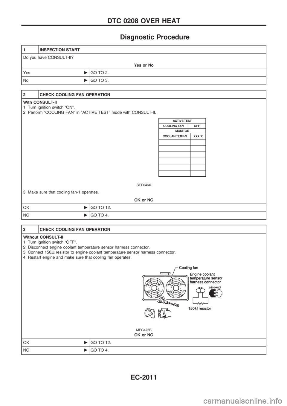
2 CHECK COOLING FAN OPERATION
With CONSULT-II
1. Turn ignition switch ªONº.
2. Perform ªCOOLING FANº in ªACTIVE TESTº mode with CONSULT-II.
SEF646X
3. Make sure that cooling fan-1 operates.
OK or NG
OKcGO TO 12.
NGcGO TO 4.
3 CHECK COOLING FAN OPERATION
Without CONSULT-II
1. Turn ignition switch ªOFFº.
2. Disconnect engine coolant temperature sensor harness connector.
3. Connect 150Wresistor to engine coolant temperature sensor harness connector.
4. Restart engine and make sure that cooling fan operates.
MEC475B
OK or NG
OKcGO TO 12.
NGcGO TO 4.
DTC 0208 OVER HEAT
EC-2011
Page 49 of 273
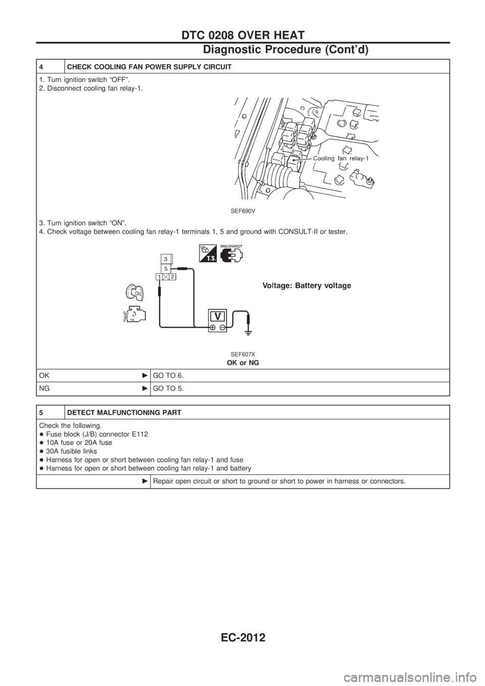
4 CHECK COOLING FAN POWER SUPPLY CIRCUIT
1. Turn ignition switch ªOFFº.
2. Disconnect cooling fan relay-1.
SEF690V
3. Turn ignition switch ªONº.
4. Check voltage between cooling fan relay-1 terminals 1, 5 and ground with CONSULT-II or tester.
SEF607X
OK or NG
OKcGO TO 6.
NGcGO TO 5.
5 DETECT MALFUNCTIONING PART
Check the following.
+Fuse block (J/B) connector E112
+10A fuse or 20A fuse
+30A fusible links
+Harness for open or short between cooling fan relay-1 and fuse
+Harness for open or short between cooling fan relay-1 and battery
cRepair open circuit or short to ground or short to power in harness or connectors.
DTC 0208 OVER HEAT
Diagnostic Procedure (Cont'd)
EC-2012
Page 50 of 273
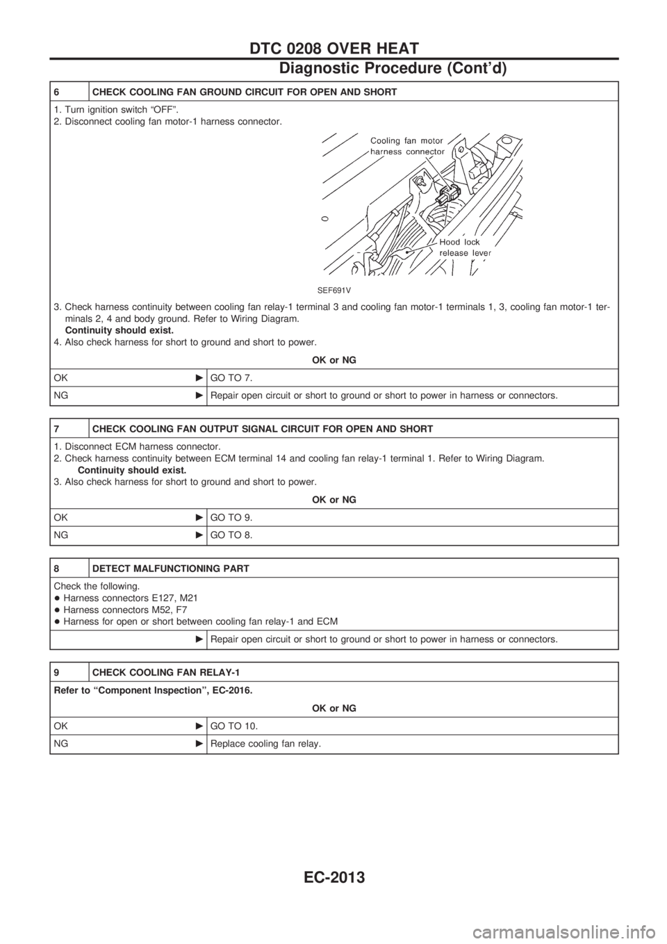
6 CHECK COOLING FAN GROUND CIRCUIT FOR OPEN AND SHORT
1. Turn ignition switch ªOFFº.
2. Disconnect cooling fan motor-1 harness connector.
SEF691V
3. Check harness continuity between cooling fan relay-1 terminal 3 and cooling fan motor-1 terminals 1, 3, cooling fan motor-1 ter-
minals 2, 4 and body ground. Refer to Wiring Diagram.
Continuity should exist.
4. Also check harness for short to ground and short to power.
OK or NG
OKcGO TO 7.
NGcRepair open circuit or short to ground or short to power in harness or connectors.
7 CHECK COOLING FAN OUTPUT SIGNAL CIRCUIT FOR OPEN AND SHORT
1. Disconnect ECM harness connector.
2. Check harness continuity between ECM terminal 14 and cooling fan relay-1 terminal 1. Refer to Wiring Diagram.
Continuity should exist.
3. Also check harness for short to ground and short to power.
OK or NG
OKcGO TO 9.
NGcGO TO 8.
8 DETECT MALFUNCTIONING PART
Check the following.
+Harness connectors E127, M21
+Harness connectors M52, F7
+Harness for open or short between cooling fan relay-1 and ECM
cRepair open circuit or short to ground or short to power in harness or connectors.
9 CHECK COOLING FAN RELAY-1
Refer to ªComponent Inspectionº, EC-2016.
OK or NG
OKcGO TO 10.
NGcReplace cooling fan relay.
DTC 0208 OVER HEAT
Diagnostic Procedure (Cont'd)
EC-2013
Page 78 of 273
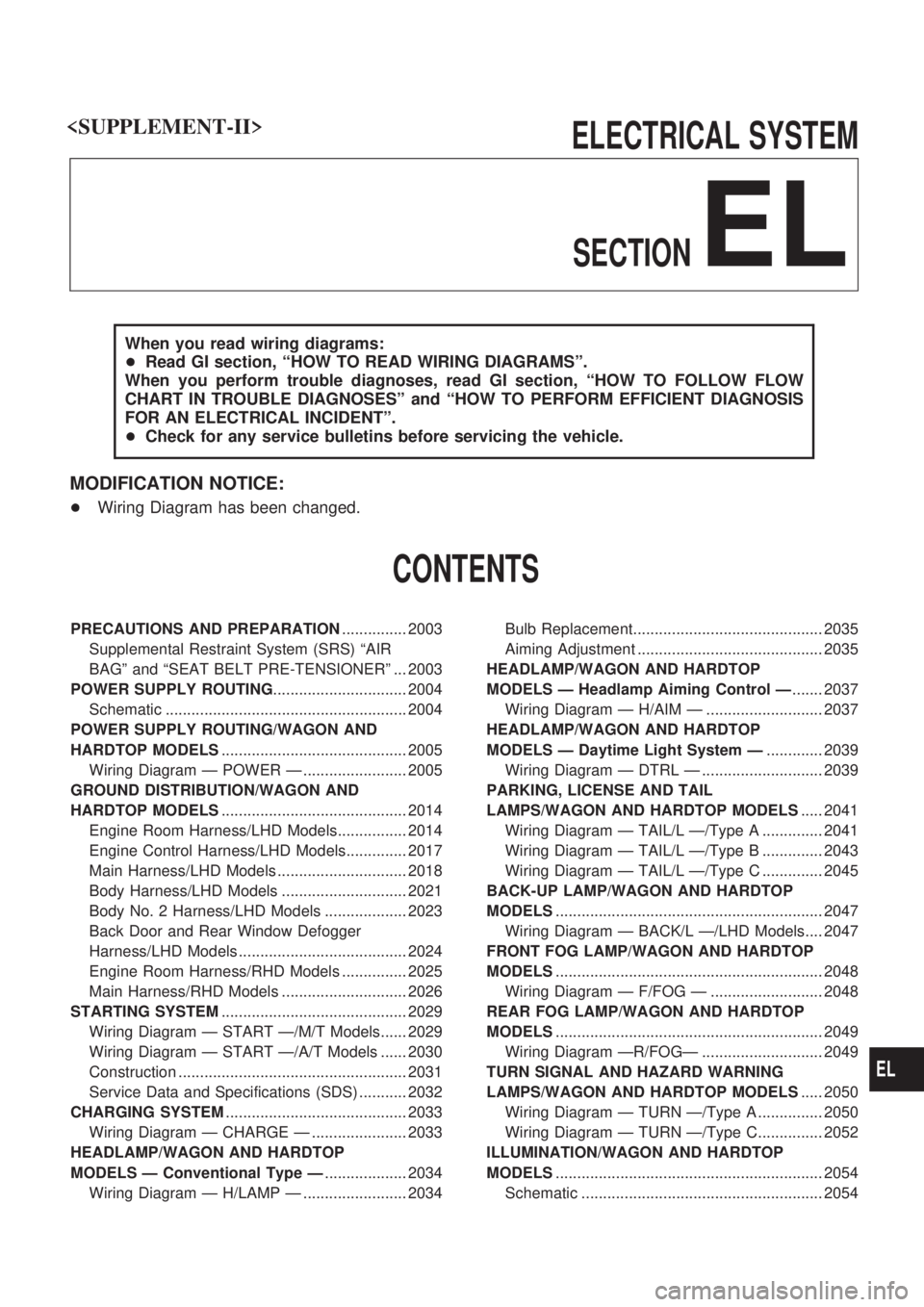
ELECTRICAL SYSTEM
SECTION
EL
When you read wiring diagrams:
+Read GI section, ªHOW TO READ WIRING DIAGRAMSº.
When you perform trouble diagnoses, read GI section, ªHOW TO FOLLOW FLOW
CHART IN TROUBLE DIAGNOSESº and ªHOW TO PERFORM EFFICIENT DIAGNOSIS
FOR AN ELECTRICAL INCIDENTº.
+Check for any service bulletins before servicing the vehicle.
MODIFICATION NOTICE:
+Wiring Diagram has been changed.
CONTENTS
PRECAUTIONS AND PREPARATION............... 2003
Supplemental Restraint System (SRS) ªAIR
BAGº and ªSEAT BELT PRE-TENSIONERº ... 2003
POWER SUPPLY ROUTING............................... 2004
Schematic ........................................................ 2004
POWER SUPPLY ROUTING/WAGON AND
HARDTOP MODELS........................................... 2005
Wiring Diagram Ð POWER Ð ........................ 2005
GROUND DISTRIBUTION/WAGON AND
HARDTOP MODELS........................................... 2014
Engine Room Harness/LHD Models................ 2014
Engine Control Harness/LHD Models.............. 2017
Main Harness/LHD Models .............................. 2018
Body Harness/LHD Models ............................. 2021
Body No. 2 Harness/LHD Models ................... 2023
Back Door and Rear Window Defogger
Harness/LHD Models ....................................... 2024
Engine Room Harness/RHD Models ............... 2025
Main Harness/RHD Models ............................. 2026
STARTING SYSTEM........................................... 2029
Wiring Diagram Ð START Ð/M/T Models...... 2029
Wiring Diagram Ð START Ð/A/T Models ...... 2030
Construction ..................................................... 2031
Service Data and Specifications (SDS) ........... 2032
CHARGING SYSTEM.......................................... 2033
Wiring Diagram Ð CHARGE Ð ...................... 2033
HEADLAMP/WAGON AND HARDTOP
MODELS Ð Conventional Type Ð................... 2034
Wiring Diagram Ð H/LAMP Ð ........................ 2034Bulb Replacement............................................ 2035
Aiming Adjustment ........................................... 2035
HEADLAMP/WAGON AND HARDTOP
MODELS Ð Headlamp Aiming Control Ð....... 2037
Wiring Diagram Ð H/AIM Ð ........................... 2037
HEADLAMP/WAGON AND HARDTOP
MODELS Ð Daytime Light System Ð............. 2039
Wiring Diagram Ð DTRL Ð ............................ 2039
PARKING, LICENSE AND TAIL
LAMPS/WAGON AND HARDTOP MODELS..... 2041
Wiring Diagram Ð TAIL/L Ð/Type A .............. 2041
Wiring Diagram Ð TAIL/L Ð/Type B .............. 2043
Wiring Diagram Ð TAIL/L Ð/Type C .............. 2045
BACK-UP LAMP/WAGON AND HARDTOP
MODELS.............................................................. 2047
Wiring Diagram Ð BACK/L Ð/LHD Models.... 2047
FRONT FOG LAMP/WAGON AND HARDTOP
MODELS.............................................................. 2048
Wiring Diagram Ð F/FOG Ð .......................... 2048
REAR FOG LAMP/WAGON AND HARDTOP
MODELS.............................................................. 2049
Wiring Diagram ÐR/FOGÐ ............................ 2049
TURN SIGNAL AND HAZARD WARNING
LAMPS/WAGON AND HARDTOP MODELS..... 2050
Wiring Diagram Ð TURN Ð/Type A ............... 2050
Wiring Diagram Ð TURN Ð/Type C............... 2052
ILLUMINATION/WAGON AND HARDTOP
MODELS.............................................................. 2054
Schematic ........................................................ 2054
EL
Page 79 of 273
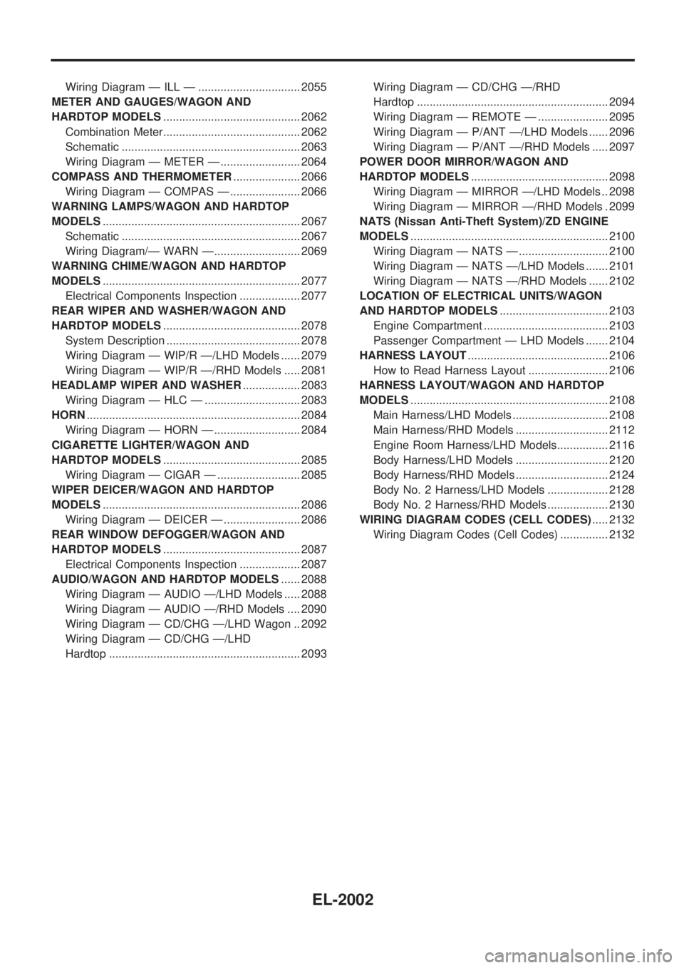
Wiring Diagram Ð ILL Ð ................................ 2055
METER AND GAUGES/WAGON AND
HARDTOP MODELS ........................................... 2062
Combination Meter........................................... 2062
Schematic ........................................................ 2063
Wiring Diagram Ð METER Ð ......................... 2064
COMPASS AND THERMOMETER ..................... 2066
Wiring Diagram Ð COMPAS Ð ...................... 2066
WARNING LAMPS/WAGON AND HARDTOP
MODELS .............................................................. 2067
Schematic ........................................................ 2067
Wiring Diagram/Ð WARN Ð........................... 2069
WARNING CHIME/WAGON AND HARDTOP
MODELS .............................................................. 2077
Electrical Components Inspection ................... 2077
REAR WIPER AND WASHER/WAGON AND
HARDTOP MODELS ........................................... 2078
System Description .......................................... 2078
Wiring Diagram Ð WIP/R Ð/LHD Models ...... 2079
Wiring Diagram Ð WIP/R Ð/RHD Models ..... 2081
HEADLAMP WIPER AND WASHER .................. 2083
Wiring Diagram Ð HLC Ð .............................. 2083
HORN ................................................................... 2084
Wiring Diagram Ð HORN Ð ........................... 2084
CIGARETTE LIGHTER/WAGON AND
HARDTOP MODELS ........................................... 2085
Wiring Diagram Ð CIGAR Ð .......................... 2085
WIPER DEICER/WAGON AND HARDTOP
MODELS .............................................................. 2086
Wiring Diagram Ð DEICER Ð ........................ 2086
REAR WINDOW DEFOGGER/WAGON AND
HARDTOP MODELS ........................................... 2087
Electrical Components Inspection ................... 2087
AUDIO/WAGON AND HARDTOP MODELS ...... 2088
Wiring Diagram Ð AUDIO Ð/LHD Models ..... 2088
Wiring Diagram Ð AUDIO Ð/RHD Models .... 2090
Wiring Diagram Ð CD/CHG Ð/LHD Wagon .. 2092
Wiring Diagram Ð CD/CHG Ð/LHD
Hardtop ............................................................ 2093 Wiring Diagram Ð CD/CHG Ð/RHD
Hardtop ............................................................ 2094
Wiring Diagram Ð REMOTE Ð ...................... 2095
Wiring Diagram Ð P/ANT Ð/LHD Models ...... 2096
Wiring Diagram Ð P/ANT Ð/RHD Models ..... 2097
POWER DOOR MIRROR/WAGON AND
HARDTOP MODELS ........................................... 2098
Wiring Diagram Ð MIRROR Ð/LHD Models .. 2098
Wiring Diagram Ð MIRROR Ð/RHD Models . 2099
NATS (Nissan Anti-Theft System)/ZD ENGINE
MODELS .............................................................. 2100
Wiring Diagram Ð NATS Ð ............................ 2100
Wiring Diagram Ð NATS Ð/LHD Models ....... 2101
Wiring Diagram Ð NATS Ð/RHD Models ...... 2102
LOCATION OF ELECTRICAL UNITS/WAGON
AND HARDTOP MODELS .................................. 2103
Engine Compartment ....................................... 2103
Passenger Compartment Ð LHD Models ....... 2104
HARNESS LAYOUT ............................................ 2106
How to Read Harness Layout ......................... 2106
HARNESS LAYOUT/WAGON AND HARDTOP
MODELS .............................................................. 2108
Main Harness/LHD Models .............................. 2108
Main Harness/RHD Models ............................. 2112
Engine Room Harness/LHD Models................ 2116
Body Harness/LHD Models ............................. 2120
Body Harness/RHD Models ............................. 2124
Body No. 2 Harness/LHD Models ................... 2128
Body No. 2 Harness/RHD Models ................... 2130
WIRING DIAGRAM CODES (CELL CODES) ..... 2132
Wiring Diagram Codes (Cell Codes) ............... 2132
EL-2002
Page 80 of 273
Supplemental Restraint System (SRS) ªAIR
BAGº and ªSEAT BELT PRE-TENSIONERº
The Supplemental Restraint System such as ªAIR BAGº and ªSEAT BELT PRE-TENSIONERº used along
with a seat belt, helps to reduce the risk or severity of injury to the driver and front passenger for certain
types of collision. The SRS system composition which is available to NISSAN MODEL Y61 is as follows (The
composition varies according to the destination and optional equipment.):
+For a frontal collision
The Supplemental Restraint System consists of driver air bag module (located in the center of the
steering wheel), front passenger air bag module (located on the instrument panel on passenger side),
seat belt pre-tensioners, a diagnosis sensor unit, warning lamp, wiring harness and spiral cable.
+For a side collision
The Supplemental Restraint System consists of front side air bag module (located in the outer side of
front seat), satellite sensor, diagnosis sensor unit (one of components of air bags for a frontal collision),
wiring harness, warning lamp (one of components of air bags for a frontal collision).
Information necessary to service the system safely is included in theRS sectionof this Service Manual.
WARNING:
+To avoid rendering the SRS inoperative, which could increase the risk of personal injury or death
in the event of a collision which would result in air bag inflation, all maintenance should be per-
formed by an authorized NISSAN dealer.
+Improper maintenance, including incorrect removal and installation of the SRS, can lead to per-
sonal injury caused by intentional activation of the system. For removal of Spiral Cable and Air
Bag Module, see the RS section.
+Do not use electrical test equipment on any circuit related to the SRS unless instructed to in this
Service Manual. SRS wiring harnesses can be identified by yellow harness connector.
PRECAUTIONS AND PREPARATION
EL-2003
Page 91 of 273

Engine Room Harness/LHD Models
CEL210M
GROUND DISTRIBUTION/WAGON AND HARDTOP MODELS
EL-2014